Skip to product information
1 of 12

PayPal, credit cards. Download editable-PDF and invoice in 1 second!

GB/T 29768-2013 English PDF (GB/T29768-2013)

GB/T 29768-2013 English PDF (GB/T29768-2013)

Regular price $555.00 USD
Regular price Sale price $555.00 USD
Sale Sold out
Shipping calculated at checkout.
Delivery: 3 seconds. Download true-PDF + Invoice.
Get Quotation: Click GB/T 29768-2013 (Self-service in 1-minute)
Historical versions (Master-website): GB/T 29768-2013
Preview True-PDF (Reload/Scroll-down if blank)

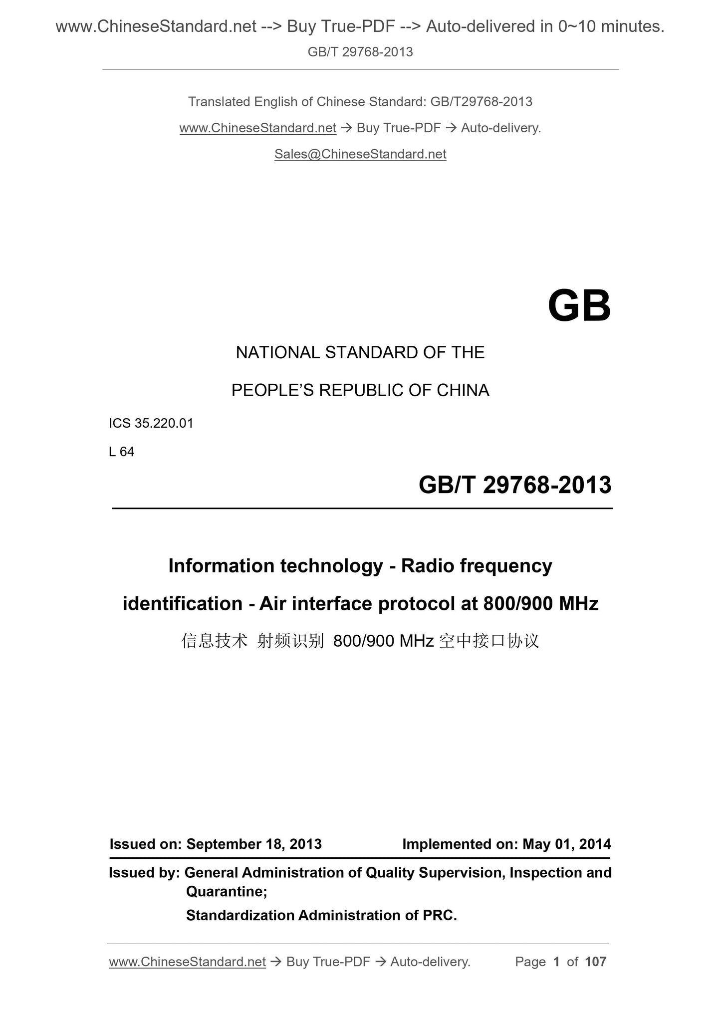
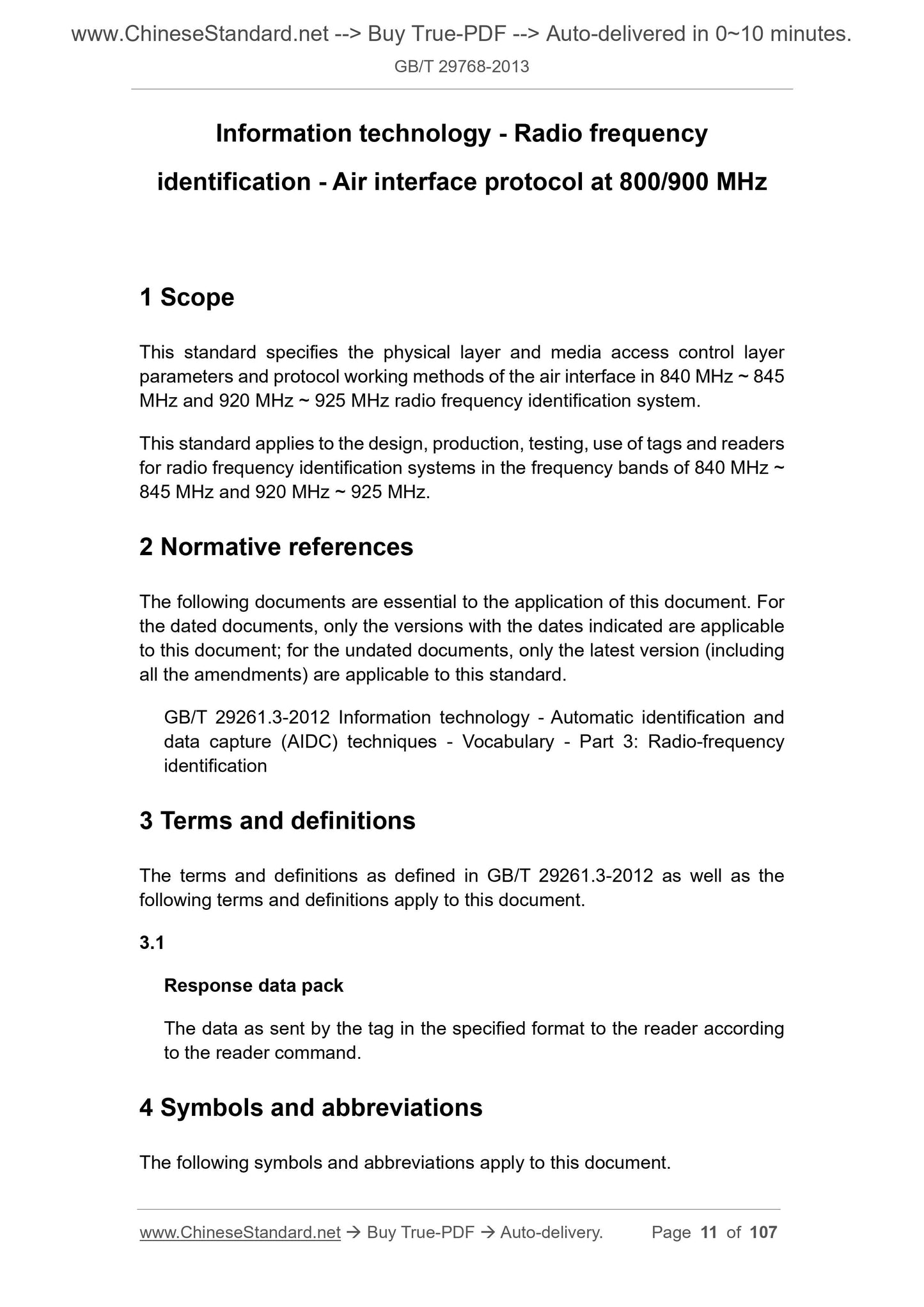
GB/T 29768-2013: Information technology - Radio frequency identification - Air interface protocol at 800/900 MHz
GB/T 29768-2013
Information technology - Radio frequency identification - Air interface protocol at 800/900 MHz
ICS 35.220.01
L64
National Standards of People's Republic of China
Information Technology Radio Frequency Identification 800/900MHz Air Interface Protocol
Released on.2013-09-18
2014-05-01 Implementation
General Administration of Quality Supervision, Inspection and Quarantine of the People's Republic of China
Issued by China National Standardization Administration
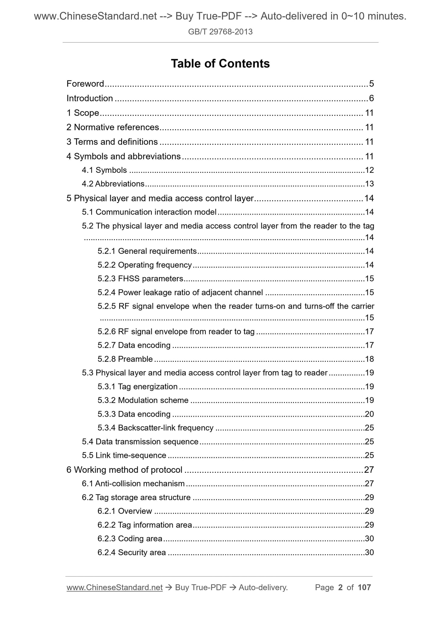
Table of contents
Preface Ⅴ
Introduction Ⅵ
1 Scope 1
2 Normative references 1
3 Terms and definitions 1
4 Symbols and abbreviations 1
4.1 Symbol 1
4.2 Abbreviations 2
5 Physical layer and media access control layer 2
5.1 Communication interaction model 2
5.2 Physical layer and media access control layer from reader to tag 3
5.2.1 General requirements 3
5.2.2 Operating frequency 3
5.2.3 FHSS parameters 3
5.2.4 Adjacent channel power leakage ratio 3
5.2.5 RF signal envelope when the reader opens and closes the carrier 4
5.2.6 RF signal envelope from reader to tag 5
5.2.7 Data encoding 5
5.2.8 Preamble 6
5.3 Physical layer and media access control layer from tag to reader 7
5.3.1 Label power-on 7
5.3.2 Modulation method 7
5.3.3 Data encoding 7
5.3.4 Reverse link frequency 12
5.4 Data Transmission Sequence 12
5.5 Link timing 12
6 How the agreement works 13
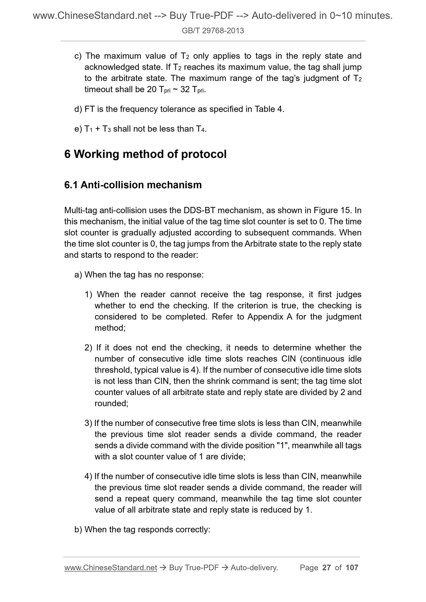
6.1 Anti-collision mechanism 13
6.2 Tag storage area structure 15
6.2.1 Overview 15
6.2.2 Label information area 15
6.2.3 Code area 15
6.2.4 Safe Zone 16
6.2.5 User area 17
6.3 Label flag bit 19
6.3.1 Match flag 19
6.3.2 Session and inventory mark 19
6.4 Label status 20
6.4.1 General requirements 20
6.4.2 State transition 20
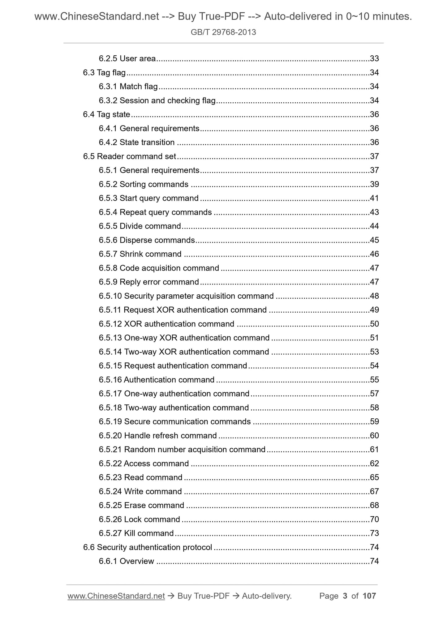
6.5 Reader command set 21
6.5.1 General requirements 21
6.5.2 Classification commands 22
6.5.3 Start query command 23
6.5.4 Repeat query commands 24
6.5.5 Split Command 25
6.5.6 Scatter Command 25
6.5.7 Shrink commands 26
6.5.8 Code acquisition command 27
6.5.9 Response to wrong commands 27
6.5.10 Security parameter acquisition command 28
6.5.11 Request XOR authentication command 28
6.5.12 XOR authentication command 29
6.5.13 One-way XOR authentication command 30
6.5.14 Two-way XOR authentication command 31
6.5.15 Request authentication command 32
6.5.16 Authentication command 33
6.5.17 One-way authentication command 34
6.5.18 Two-way authentication command 34
6.5.19 Safety communication commands 35
6.5.20 Handle update command 36
6.5.21 Random number acquisition command 37
6.5.22 Access commands 38
6.5.23 Read command 39
6.5.24 Write command 41
6.5.25 Erase Command 42
6.5.26 Lock command 43
6.5.27 Inactivation command 45
6.6 Security authentication protocol 45
6.6.1 Overview 45
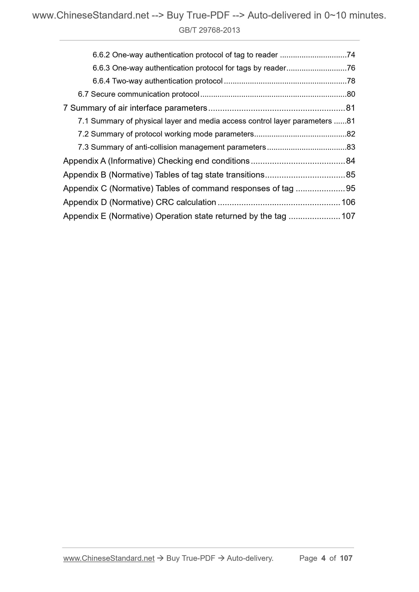
6.6.2 One-way authentication protocol of tag to reader 46
6.6.3 One-way authentication protocol for tags by reader 47
6.6.4 Two-way authentication protocol 48
6.7 Secure communication protocol 50
7 Summary of Air Interface Parameters 51
7.1 Summary of physical layer and media access control layer parameters 51
7.2 Summary of protocol working mode parameters 52
7.3 Summary of anti-collision management parameters 52
Appendix A (informative appendix) Inventory end conditions 53
Appendix B (Normative Appendix) Label State Transition Table 54
Appendix C (Normative Appendix) Label Command Response Table 64
Appendix D (normative appendix) CRC calculation 76
Appendix E (Normative Appendix) Operation Status Returned by Label 77
Preface
This standard was drafted in accordance with the rules given in GB/T 1.1-2009.
This standard was proposed and managed by the National Information Technology Standardization Technical Committee (SAC/TC28).
1 Scope
This standard specifies the physical layer of the air interface of the radio frequency identification system in the frequency bands of 840MHz~845MHz and 920MHz~925MHz
And media access control layer parameters and protocol working methods.
This standard is applicable to the design of 840MHz~845MHz and 920MHz~925MHz radio frequency identification system tags and readers.
Design, production, testing and use.
2 Normative references
The following documents are indispensable for the application of this document. For dated reference documents, only the dated version applies to this article
Pieces. For undated references, the latest version (including all amendments) applies to this document.
GB/T 29261.3-2012 Information Technology Automatic Identification and Data Acquisition Technology Vocabulary Part 3.Radio Frequency Identification
3 Terms and definitions
The following terms and definitions defined in GB/T 29261.3-2012 apply to this document.
3.1
Response packet
The tag sends data in the specified format to the reader according to the reader command.
4 Symbols and abbreviations
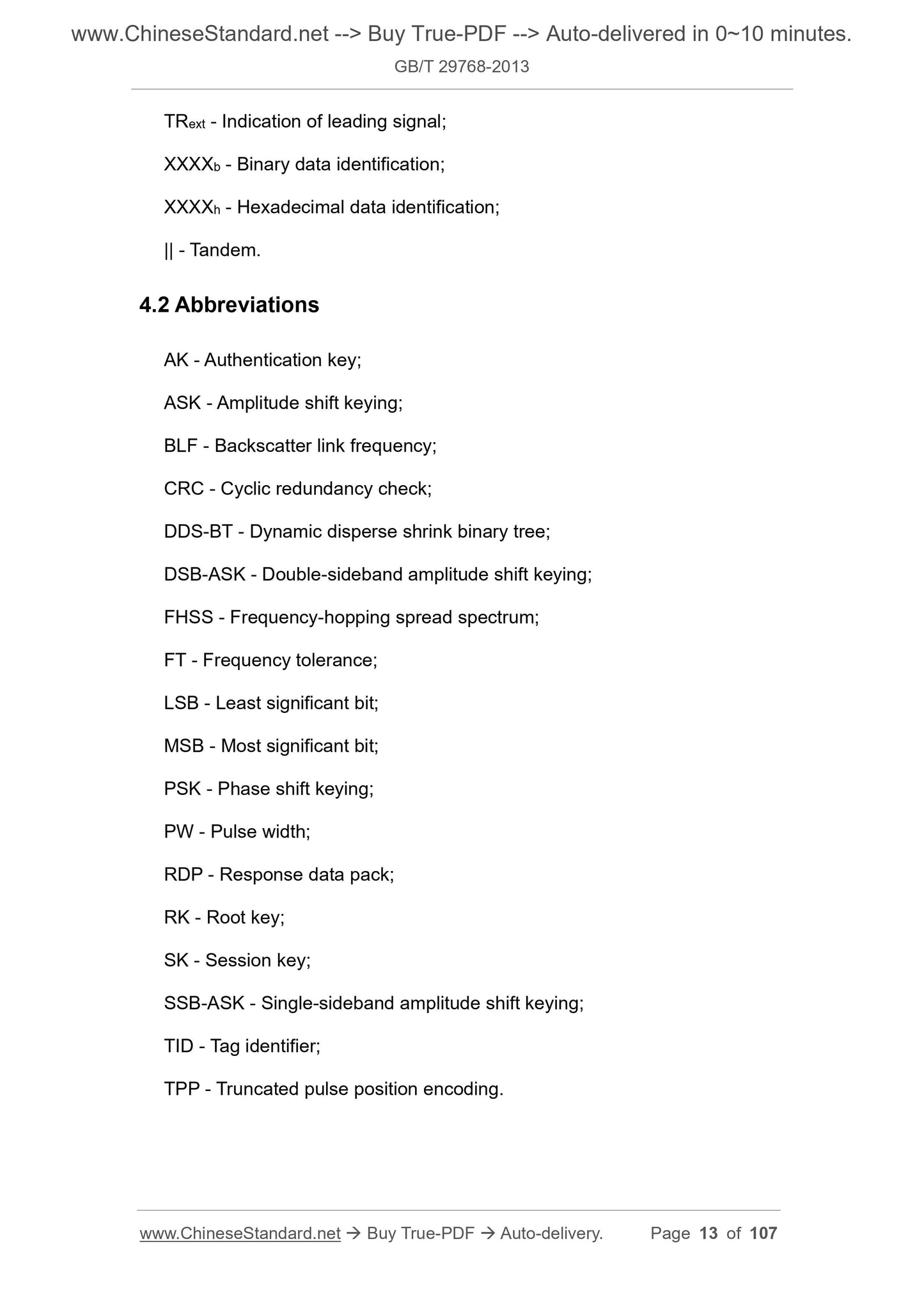
The following symbols and abbreviations apply to this document.
4.1 Symbols
5 Physical layer and media access control layer
5.1 Communication interaction model
The reader uses TPP to encode the baseband data, uses DSB-ASK or SSB-ASK to modulate the radio frequency carrier,
Or multiple tags to send commands. After the command is sent, the reader continues to send the unmodulated radio frequency carrier and listens to the response packet from the tag.
The tag obtains working energy from the radio frequency carrier sent by the reader, and uses FM0 or Miller coding to encode the baseband data.
Backscatter modulates the amplitude and/or phase of the radio frequency carrier.
Use half-duplex communication between reader and tag. When communicating, the reader first sends the command, and the tag is based on the command of the reader.
Order to perform the corresponding operation, when needed, send a response packet.
5.2 The physical layer and media access control layer from the reader to the tag
5.2.1 General requirements
The reader uses TPP to encode baseband data. The reader should support DSB-ASK or SSB-ASK modulation
The signature should be able to demodulate the modulation modes of DSB-ASK and SSB-ASK.
5.2.2 Operating frequency
The working frequency of the reader is 840MHz~845MHz and 920MHz~925MHz. There are a total of 40 channels in the frequency band, and the channel center frequency
The rate fc is determined by equation (1) or equation (2), and the bandwidth of each channel is 250kHz.
5.2.3 FHSS parameters
When the reader uses FHSS communication, it should use the 40 channels specified in 5.2.2, and the maximum residence time of each channel is 2s.
5.2.4 Adjacent channel power leakage ratio
The adjacent channel power leakage ratio of the reader is shown in Figure 1.
Figure 1 The adjacent channel power leakage ratio of the reader
The ratio of the power P(R) of the reader in the transmitting channel R to the power P(S) of other channels S should meet the following requirements.
5.2.5 RF signal envelope when the reader opens and closes the carrier
The RF signal envelope when the reader opens and closes the carrier is shown in Figure 2.The RF signal envelope parameters when the carrier is turned on should meet
The provisions of Table 1.
5.2.6 RF signal envelope from reader to tag
The radio frequency signal envelope from the reader to the tag is shown in Figure 3.
5.2.7 Data encoding
The reader uses the TPP shown in Figure 4 to encode the baseband data.
Figure 4 TPP symbol
In Figure 4, the duration of the symbol 00 is 2Tc, the duration of the symbol 01 is 3Tc, the duration of the symbol 11 is 4Tc, and the symbol 10
The duration of the symbol is 5Tc, and the length tolerance of the four symbols is ±1%.
Tc can be 6.25μs or 12.5μs, and the length tolerance is ±1%. The reader should use a fixed Tc in an inventory cycle.
When the length of the data packet is an odd number, the last bit is filled with 0 before encoding.
5.2.8 Preamble
The forward link should use the preamble communication as shown in Figure 5.The preamble is composed of separator, calibration symbol one and calibration symbol two. Delimiter
The length tolerance is ±5%, and the length tolerance of calibration symbol 1 and calibration symbol 2 are both ±1%.
Figure 5 The preamble of the forward link
The label should measure the time Tcal1 of the calibration symbol 1 and the time Tcal2 of the calibration symbol 2, and the forward chain can be calculated according to formula (3), formula (4) and formula (5)
The decoding reference time Pivot1, Pivot2 and Pivot3 of the road.
After receiving the preamble, the tag measures the interval between the rising edges of two consecutive pulses, and should be decoded according to the following methods.
a) The interval time is less than Pivot1, decoded as symbol 00;
b) The interval time is less than Pivot2 and not less than Pivot1, decoded as symbol 01;
c) The interval time is not less than Pivot2 and less than Pivot3, decoded as symbol 11;
d) The interval time is not less than Pivot3, decoded as symbol 10.
5.3 Physical layer and media access control layer from tag to reader
5.3.1 Label power up
The tag should be powered on within the maximum stable time described in Table 1, and be ready to receive reader commands.
5.3.2 Modulation method
The label backscatter should adopt ASK and (or) PSK modulation, the reader should be able to demodulate the above two modulation methods.
5.3.3 Data encoding
5.3.3.1 General requirements
The tag should be able to perform FM0 encoding and Miller encoding on baseband data.
5.3.3.2 FM0
5.3.3.2.1 Baseband coding
Figure 6 shows the basic functions of FM0 and the state diagram of FM0.
5.3.3.2.2 FM0 preamble
When using FM0 on the reverse link, one of the two preambles shown in Figure 9 should be used as the preamble.
The TRext data field is determined, but when the tag receives a write command, an erase command, a lock command or a deactivation command, it does not matter the TRext data
Regardless of the domain, the tags respond as TRext=1b.
5.3.3.3.2 Miller subcarrier
When Miller coding is used on the reverse link, subcarriers should be used, and the subcarrier coefficient M can be selected to be 2, 4 or 8.
The code selection in the command is determined by the data domain. Figure 11 shows the Miller subcarrier sequence when the subcarrier coefficients are different. Symbol 0 or symbol 1
The nominal value of the duty cycle is 50%, the minimum is 45%, and the maximum is 55%.
a) Miller subcarrier sequence with M=2
b) Miller subcarrier sequence with M=4
c) Miller subcarrier sequence with M=8
Figure 11 Miller subcarrier sequence
At the end of the coding sequence, a redundant symbol 1 shall be used as the end bit, as shown in Figure 12.
a) Miller subcarrier end bit with M=2
b) Miller subcarrier end bit with M=4
c) Miller subcarrier end bit with M=8
Figure 12 Miller subcarrier end bit
5.3.3.3.3 Miller encoding preamble
When Miller coding is used in the reverse link, one of the two preambles shown in Figure 13 should be used as the preamble, which is specified by the start query command
The TRext data field in the decision, but when the tag receives a write command, erase command, lock command or deactivate command, regardless of TRext
Regardless of the data field, the label responds as TRext=1b.
a) Miller subcarrier preamble (TRext=0b)
b) Miller subcarrier preamble (TRext=1b)
Figure 13 Preamble of Miller subcarrier
5.3.4 Reverse link frequency
The reverse link frequency is determined by the reverse link rate factor data field in the start query command, and the reverse link frequency can be calculated according to equation (6)
The specific value of the reverse link frequency is shown in Table 4.
6.2 Tag storage area structure
6.2.1 Overview
The storage of tags is divided into four logical storage areas. tag information area, coding area, security area and user area. Among them, the user area is an optional area.
Each logical storage area contains one or more words, see Figure 16.
Note. 00h represents the address of bit 0 in word 0, and 0Fh represents the address of bit 15 in word 0.
Figure 16 Tag storage area structure
6.2.2 Label Information Area
00h~07h in the tag information area store the assigned identifier in the tag TID. The location above 08h in the label information area stores the divided points
With other data other than the identifier.
The data in the tag information area is written when the tag chip leaves the factory, and cannot be modified after being written.
6.2.3 Coding area
The encoding area stores data such as encoding. The length of the coding area is not fixed, the specific structure is shown in Figure 17.
Note. MSB and LSB respectively represent the most significant bit and the least significant bit of the data.
Figure 17 The structure of the coding region
The code area is composed of three parts. code length, code header and code.
a) Code length. 00h~07h in the code area store the length of the code, in words as the unit. When the reader writes data to the encoding area, such as
If the length of the code to be written exceeds the storage range of the code area, the tag will return the error code of the storage area overflow, see Appendix E.
b) Encoding. If the actual length of the encoding is not word-aligned, 0 is filled before the highest bit of the encoding when writing the encoding area, so that
The data written in the coding area is aligned word by word.
6.2.4 Safe Zone
6.2.4.1 Security zone division
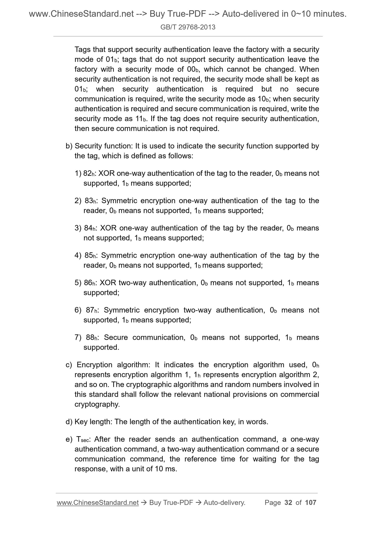
The security of the label is divided into 3 sub-zones, as shown in Figure 18.Each sub-area can be subdivided into several fields, and each field can be accessed and
It is locked and cannot be crossed during access. The modification to the safety zone data will take effect after power failure.
The reader can read the safety parameters in the safety zone by using the safety parameter acquisition command, and other data in the safety zone are not readable.
Note. 00h represents the address of bit 0 in word 0, and 0Fh represents the address of bit 15 in word 0.
Figure 18 The structure of the security zone
6.2.4.2 Subzone One
The first subarea stores the inactivation passwo...
View full details