GB/T 28046.2-2019 English PDF (GBT28046.2-2019)
Regular price
$255.00 USD
Regular price
Sale price
$255.00 USD
Unit price
/
per
Delivery: 3 seconds. Download true-PDF + Invoice.
Get QUOTATION in 1-minute: Click GB/T 28046.2-2019
Historical versions: GB/T 28046.2-2019
Preview True-PDF (Reload/Scroll if blank)
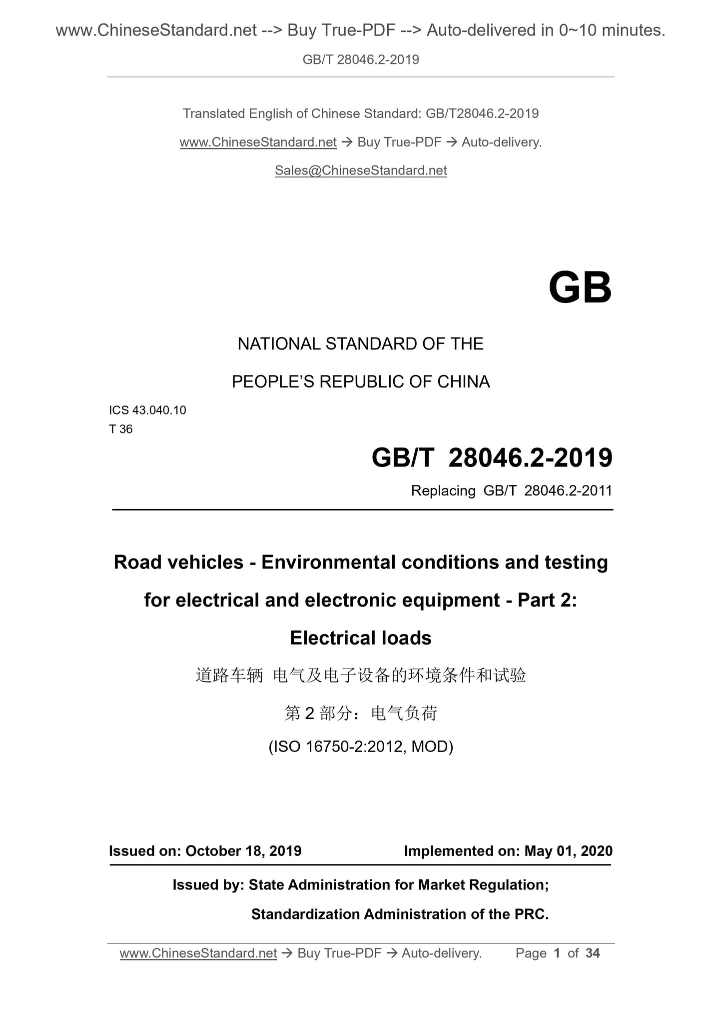
GB/T 28046.2-2019: Road vehicles -- Environmental conditions and testing for electrical and electronic equipment -- Part 2: Electrical loads
GB/T 28046.2-2019
NATIONAL STANDARD OF THE
PEOPLE’S REPUBLIC OF CHINA
ICS 43.040.10
T 36
Replacing GB/T 28046.2-2011
Road vehicles - Environmental conditions and testing
for electrical and electronic equipment - Part 2:
Electrical loads
(ISO 16750-2:2012, MOD)
ISSUED ON: OCTOBER 18, 2019
IMPLEMENTED ON: MAY 01, 2020
Issued by: State Administration for Market Regulation;
Standardization Administration of the PRC.
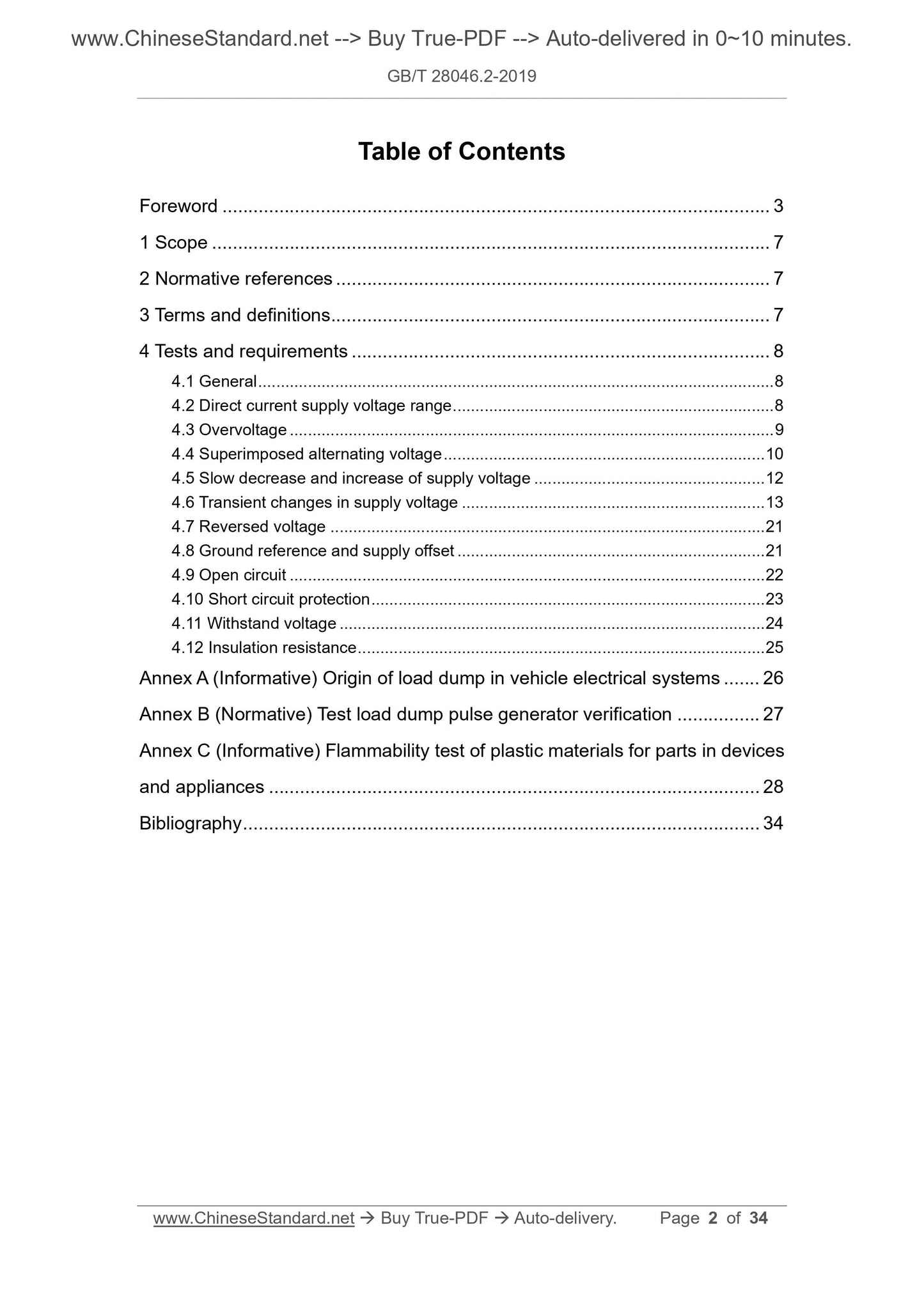
Table of Contents
Foreword ... 3
1 Scope ... 7
2 Normative references ... 7
3 Terms and definitions ... 7
4 Tests and requirements ... 8
4.1 General ... 8
4.2 Direct current supply voltage range ... 8
4.3 Overvoltage ... 9
4.4 Superimposed alternating voltage ... 10
4.5 Slow decrease and increase of supply voltage ... 12
4.6 Transient changes in supply voltage ... 13
4.7 Reversed voltage ... 21
4.8 Ground reference and supply offset ... 21
4.9 Open circuit ... 22
4.10 Short circuit protection ... 23
4.11 Withstand voltage ... 24
4.12 Insulation resistance ... 25
Annex A (Informative) Origin of load dump in vehicle electrical systems ... 26
Annex B (Normative) Test load dump pulse generator verification ... 27
Annex C (Informative) Flammability test of plastic materials for parts in devices
and appliances ... 28
Bibliography ... 34
Road vehicles - Environmental conditions and testing
for electrical and electronic equipment - Part 2:
Electrical loads
1 Scope
This Part of GB/T 28046 describes the electrical environmental loads of
electrical and electronic equipment on the vehicles and specifies the tests and
requirements.
This Part applies to type M, N, O automotive electrical and electronic
systems/components. Type L vehicle systems/components may refer to it.
2 Normative references
The following documents are indispensable for the application of this document.
For the dated references, only the editions with the dates indicated are
applicable to this document. For the undated references, the latest edition
(including all the amendments) are applicable to this document.
GB/T 28046.1 Road vehicles - Environmental conditions and testing for
electrical and electronic equipment - Part 1: General (GB/T 28046.1-2011,
ISO 16750-1:2006, MOD)
GB/T 28046.4-2011 Road vehicles - Environmental conditions and testing for
electrical and electronic equipment - Part 4: Climatic loads (ISO 16750-
4:2006, MOD)
GB/T 31465 (all parts) Road vehicles - Fuse-link [ISO 8820 (all parts)]
3 Terms and definitions
For the purposes of this document, the terms and definitions given in GB/T
28046.1 apply.
The functional status shall be minimum class D. Functional status shall be class
B where more stringent requirements are necessary.
4.3.2 24 V system
4.3.2.1 Purpose
SIMULATE the condition where the generator regulator fails, so that the output
voltage of the generator rises above normal values.
4.3.2.2 Test at Tmax - 20 °C
HEAT the DUT in a hot air oven to a temperature of Tmax - 20 °C. Apply a voltage
of 36 V for 60 min to valid inputs of the DUT.
4.3.2.3 Requirement
The functional status shall be minimum class C. Functional status shall be class
A where more stringent requirements are necessary.
4.4 Superimposed alternating voltage
4.4.1 Purpose
SIMULATE the ripple voltage which occurs under d.c. supply.
4.4.2 Test
Connect the DUT as shown in Figure 1; TEST the valid inputs of the DUT
according to the following regulations. Severity level 1, 2, 3, or 4 may be
selected according to actual needs. The test conditions are as follows:
- Maximum supply voltage US max (see Figure 2): 16 V (for 12 V system); 32
V (for 24 V system);
- Alternating current voltage (sinusoidal):
Severity 1: Upp=1 V (for 12 V and 24 V systems);
Severity 2: Upp=4 V (for 12 V and 24 V systems);
Severity 3: Upp=10 V (only for 24 V system);
Severity 4: Upp=2 V (only for 12 V system).
- Internal resistance of power supply: 50 mΩ~100 mΩ;
- Frequency range (see Figure 3): 50 Hz~25 kHz;
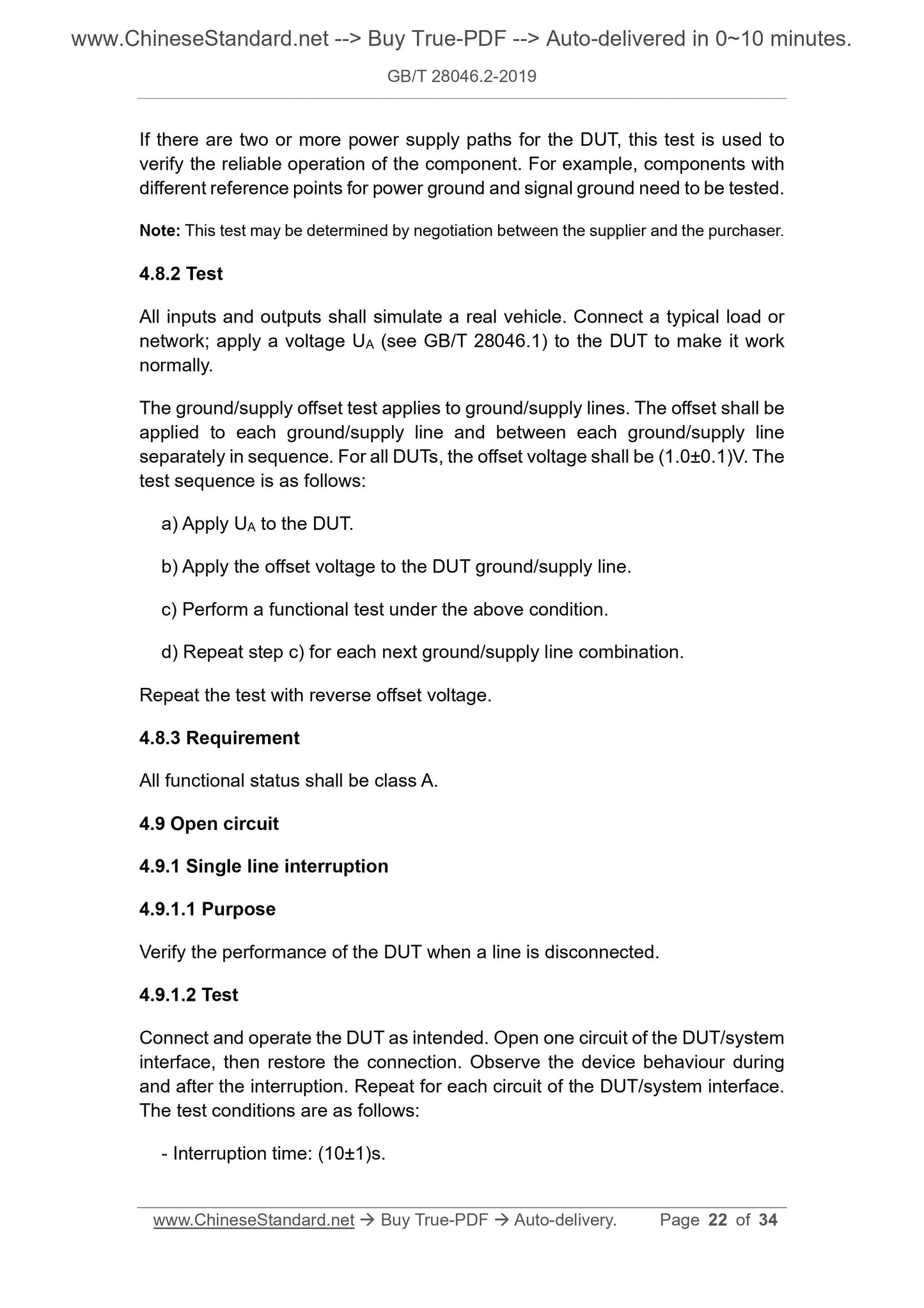
If there are two or more power supply paths for the DUT, this test is used to
verify the reliable operation of the component. For example, components with
different reference points for power ground and signal ground need to be tested.
Note: This test may be determined by negotiation between the supplier and the purchaser.
4.8.2 Test
All inputs and outputs shall simulate a real vehicle. Connect a typical load or
network; apply a voltage UA (see GB/T 28046.1) to the DUT to make it work
normally.
The ground/supply offset test applies to ground/supply lines. The offset shall be
applied to each ground/supply line and between each ground/supply line
separately in sequence. For all DUTs, the offset voltage shall be (1.0±0.1)V. The
test sequence is as follows:
a) Apply UA to the DUT.
b) Apply the offset voltage to the DUT ground/supply line.
c) Perform a functional test under the above condition.
d) Repeat step c) for each next ground/supply line combination.
Repeat the test with reverse offset voltage.
4.8.3 Requirement
All functional status shall be class A.
4.9 Open circuit
4.9.1 Single line interruption
4.9.1.1 Purpose
Verify the performance of the DUT when a line is disconnected.
4.9.1.2 Test
Connect and operate the DUT as intended. Open one circuit of the DUT/system
interface, then restore the connection. Observe the device behaviour during
and after the interruption. Repeat for each circuit of the DUT/system interface.
The test conditions are as follows:
- Interruption time: (10±1)s.
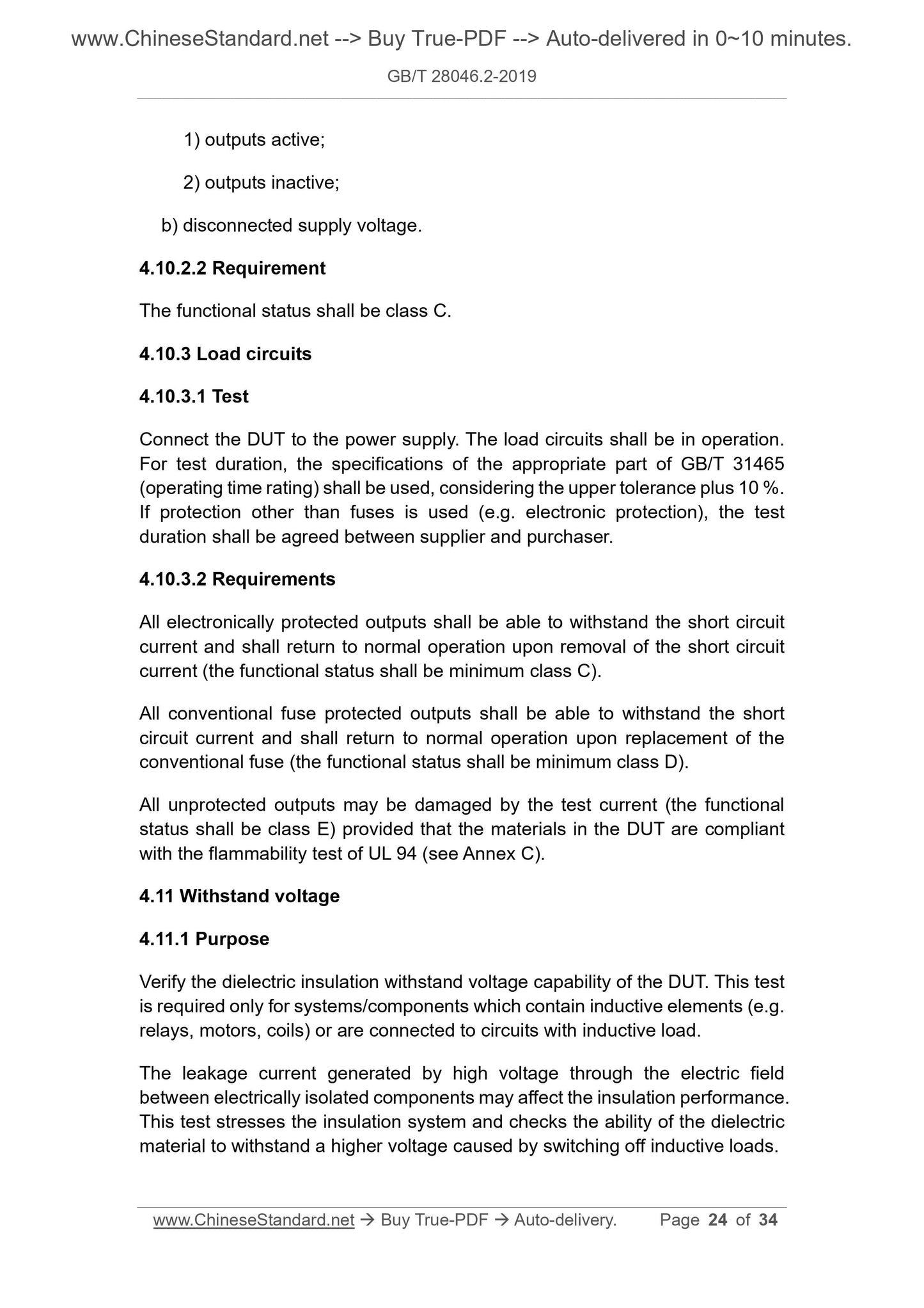
1) outputs active;
2) outputs inactive;
b) disconnected supply voltage.
4.10.2.2 Requirement
The functional status shall be class C.
4.10.3 Load circuits
4.10.3.1 Test
Connect the DUT to the power supply. The load circuits shall be in operation.
For test duration, the specifications of the appropriate part of GB/T 31465
(operating time rating) shall be used, considering the upper tolerance plus 10 %.
If protection other than fuses is used (e.g. electronic protection), the test
duration shall be agreed between supplier and purchaser.
4.10.3.2 Requirements
All electronically protected outputs shall be able to withstand the short circuit
current and shall return to normal operation upon removal of the short circuit
current (the functional status shall be minimum class C).
All conventional fuse protected outputs shall be able to withstand the short
circuit current and shall return to normal operation upon replacement of the
conventional fuse (the functional status shall be minimum class D).
All unprotected outputs may be damaged by the test current (the functional
status shall be class E) provided that the materials in the DUT are compliant
with the flammability test of UL 94 (see Annex C).
4.11 Withstand voltage
4.11.1 Purpose
Verify the dielectric insulation withstand voltage capability of the DUT. This test
is required only for systems/components which contain inductive elements (e.g.
relays, motors, coils) or are connected to circuits with inductive load.
The leakage current generated by high voltage through the electric field
between electrically isolated components may affect the insulation performance.
This test stresses the insulation system and checks the ability of the dielectric
material to withstand a higher voltage caused by switching off inductive loads.
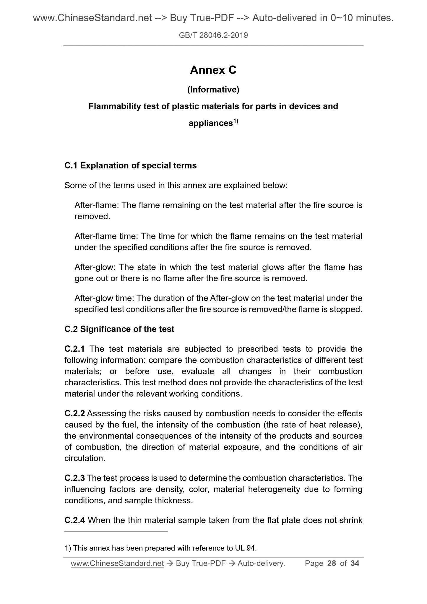
Annex C
(Informative)