1
/
of
7
www.ChineseStandard.us -- Field Test Asia Pte. Ltd.
GB/T 27698.3-2023 English PDF (GB/T27698.3-2023)
Regular price
$245.00
Regular price
Sale price
$245.00
Unit price
/
per
Shipping calculated at checkout.
Couldn't load pickup availability
GB/T 27698.3-2023: Test methods for the performance of heat exchangers and heat exchange elements - Part 3: Heat exchanger elements
Delivery: 9 seconds. Download (and Email) true-PDF + Invoice.
Get Quotation: Click GB/T 27698.3-2023 (Self-service in 1-minute)
Historical versions (Master-website): GB/T 27698.3-2023
Preview True-PDF (Reload/Scroll-down if blank)
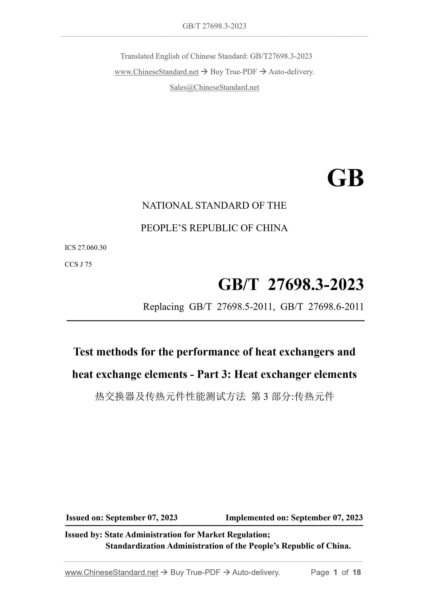
GB/T 27698.3-2023
GB
NATIONAL STANDARD OF THE
PEOPLE’S REPUBLIC OF CHINA
ICS 27.060.30
CCS J 75
Replacing GB/T 27698.5-2011, GB/T 27698.6-2011
Test methods for the performance of heat exchangers and
heat exchange elements - Part 3: Heat exchanger elements
ISSUED ON: SEPTEMBER 07, 2023
IMPLEMENTED ON: SEPTEMBER 07, 2023
Issued by: State Administration for Market Regulation;
Standardization Administration of the People’s Republic of China.
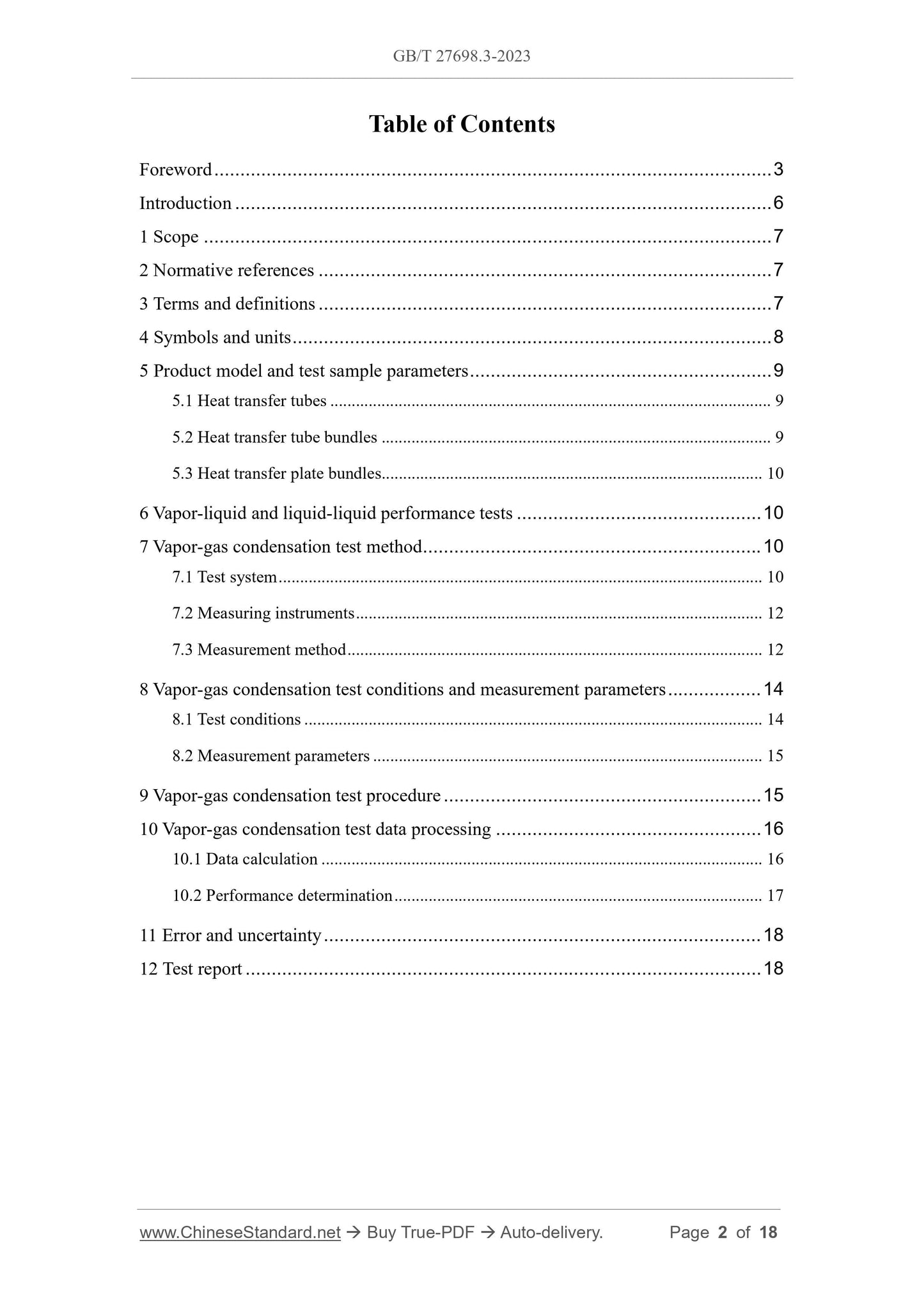
Table of Contents
Foreword ... 3
Introduction ... 6
1 Scope ... 7
2 Normative references ... 7
3 Terms and definitions ... 7
4 Symbols and units ... 8
5 Product model and test sample parameters ... 9
5.1 Heat transfer tubes ... 9
5.2 Heat transfer tube bundles ... 9
5.3 Heat transfer plate bundles ... 10
6 Vapor-liquid and liquid-liquid performance tests ... 10
7 Vapor-gas condensation test method ... 10
7.1 Test system ... 10
7.2 Measuring instruments ... 12
7.3 Measurement method ... 12
8 Vapor-gas condensation test conditions and measurement parameters ... 14
8.1 Test conditions ... 14
8.2 Measurement parameters ... 15
9 Vapor-gas condensation test procedure ... 15
10 Vapor-gas condensation test data processing ... 16
10.1 Data calculation ... 16
10.2 Performance determination ... 17
11 Error and uncertainty ... 18
12 Test report ... 18
Test methods for the performance of heat exchangers and
heat exchange elements - Part 3: Heat exchanger elements
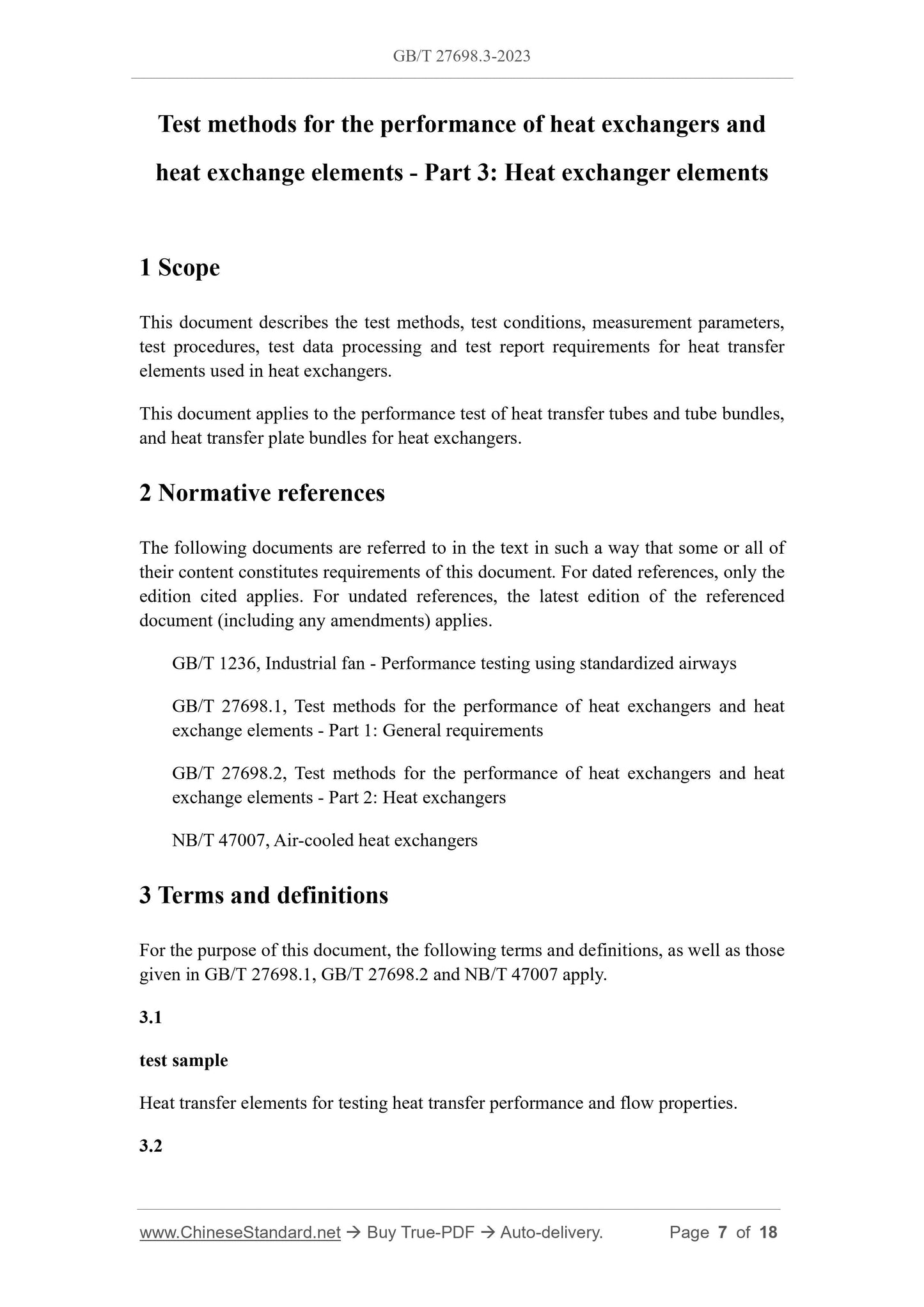
1 Scope
This document describes the test methods, test conditions, measurement parameters,
test procedures, test data processing and test report requirements for heat transfer
elements used in heat exchangers.
This document applies to the performance test of heat transfer tubes and tube bundles,
and heat transfer plate bundles for heat exchangers.
2 Normative references
The following documents are referred to in the text in such a way that some or all of
their content constitutes requirements of this document. For dated references, only the
edition cited applies. For undated references, the latest edition of the referenced
document (including any amendments) applies.
GB/T 1236, Industrial fan - Performance testing using standardized airways
GB/T 27698.1, Test methods for the performance of heat exchangers and heat
exchange elements - Part 1: General requirements
GB/T 27698.2, Test methods for the performance of heat exchangers and heat
exchange elements - Part 2: Heat exchangers
NB/T 47007, Air-cooled heat exchangers
3 Terms and definitions
For the purpose of this document, the following terms and definitions, as well as those
given in GB/T 27698.1, GB/T 27698.2 and NB/T 47007 apply.
3.1
test sample
Heat transfer elements for testing heat transfer performance and flow properties.
3.2
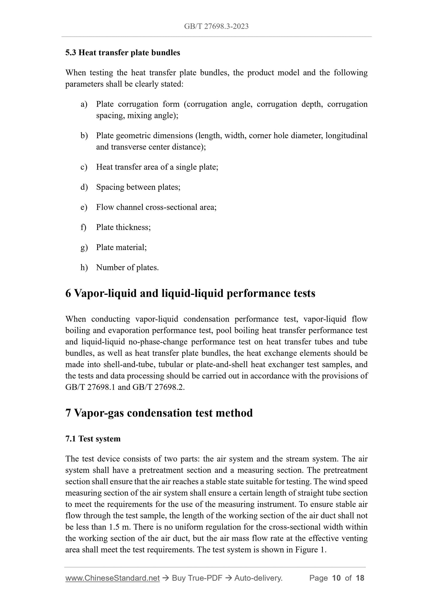
5.3 Heat transfer plate bundles
When testing the heat transfer plate bundles, the product model and the following
parameters shall be clearly stated:
a) Plate corrugation form (corrugation angle, corrugation depth, corrugation
spacing, mixing angle);
b) Plate geometric dimensions (length, width, corner hole diameter, longitudinal
and transverse center distance);
c) Heat transfer area of a single plate;
d) Spacing between plates;
e) Flow channel cross-sectional area;
f) Plate thickness;
g) Plate material;
h) Number of plates.
6 Vapor-liquid and liquid-liquid performance tests
When conducting vapor-liquid condensation performance test, vapor-liquid flow
boiling and evaporation performance test, pool boiling heat transfer performance test
and liquid-liquid no-phase-change performance test on heat transfer tubes and tube
bundles, as well as heat transfer plate bundles, the heat exchange elements should be
made into shell-and-tube, tubular or plate-and-shell heat exchanger test samples, and
the tests and data processing should be carried out in accordance with the provisions of
GB/T 27698.1 and GB/T 27698.2.
7 Vapor-gas condensation test method
7.1 Test system
The test device consists of two parts: the air system and the stream system. The air
system shall have a pretreatment section and a measuring section. The pretreatment
section shall ensure that the air reaches a stable state suitable for testing. The wind speed
measuring section of the air system shall ensure a certain length of straight tube section
to meet the requirements for the use of the measuring instrument. To ensure stable air
flow through the test sample, the length of the working section of the air duct shall not
be less than 1.5 m. There is no uniform regulation for the cross-sectional width within
the working section of the air duct, but the air mass flow rate at the effective venting
area shall meet the test requirements. The test system is shown in Figure 1.
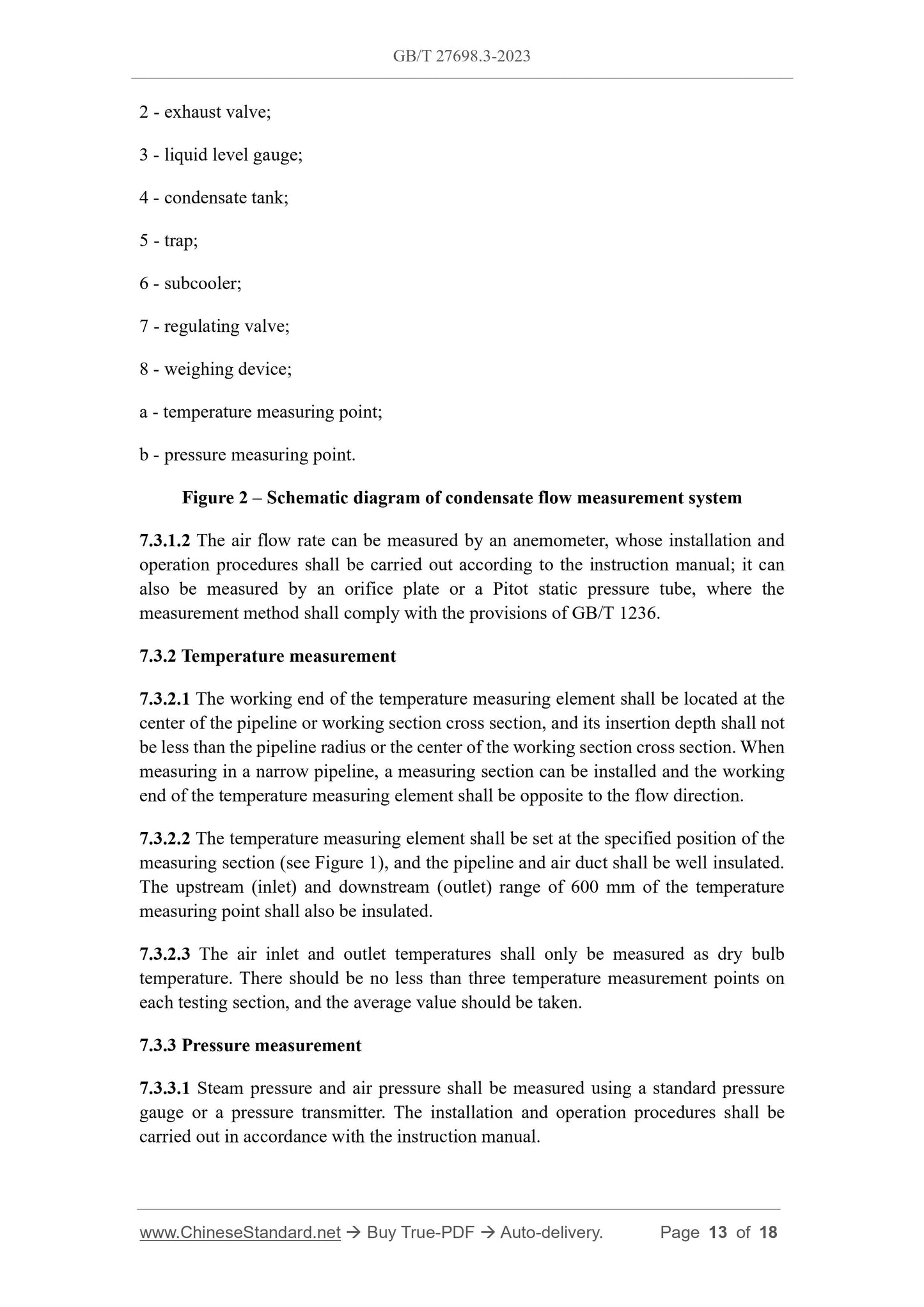
2 - exhaust valve;
3 - liquid level gauge;
4 - condensate tank;
5 - trap;
6 - subcooler;
7 - regulating valve;
8 - weighing device;
a - temperature measuring point;
b - pressure measuring point.
Figure 2 – Schematic diagram of condensate flow measurement system
7.3.1.2 The air flow rate can be measured by an anemometer, whose installation and
operation procedures shall be carried out according to the instruction manual; it can
also be measured by an orifice plate or a Pitot static pressure tube, where the
measurement method shall comply with the provisions of GB/T 1236.
7.3.2 Temperature measurement
7.3.2.1 The working end of the temperature measuring element shall be located at the
center of the pipeline or working section cross section, and its insertion depth shall not
be less than the pipeline radius or the center of the working section cross section. When
measuring in a narrow pipeline, a measuring section can be installed and the working
end of the temperature measuring element shall be opposite to the flow direction.
7.3.2.2 The temperature measuring element shall be set at the specified position of the
measuring section (see Figure 1), and the pipeline and air duct shall be well insulated.
The upstream (inlet) and downstream (outlet) range of 600 mm of the temperature
measuring point shall also be insulated.
7.3.2.3 The air inlet and outlet temperatures shall only be measured as dry bulb
temperature. There should be no less than three temperature measurement points on
each testing section, and the average value should be taken.
7.3.3 Pressure measurement
7.3.3.1 Steam pressure and air pressure shall be measured using a standard pressure
gauge or a pressure transmitter. The installation and operation procedures shall be
carried out in accordance with the instruction manual.
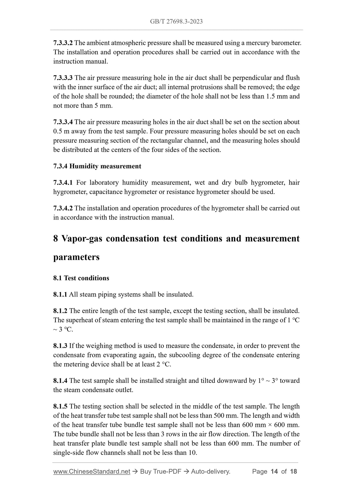
7.3.3.2 The ambient atmospheric pressure shall be measured using a mercury barometer.
The installation and operation procedures shall be carried out in accordance with the
instruction manual.
7.3.3.3 The air pressure measuring hole in the air duct shall be perpendicular and flush
with the inner surface of the air duct; all internal protrusions shall be removed; the edge
of the hole shall be rounded; the diameter of the hole shall not be less than 1.5 mm and
not more than 5 mm.
7.3.3.4 The air pressure measuring holes in the air duct shall be set on the section about
0.5 m away from the test sample. Four pressure measuring holes should be set on each
pressure measuring section of the rectangular channel, and the measuring holes should
be distributed at the centers of the four sides of the section.
7.3.4 Humidity measurement
7.3.4.1 For laboratory humidity measurement, wet and dry bulb hygrometer, hair
hygrometer, capacitance hygrometer or resistance hygrometer should be used.
7.3.4.2 The installation and operation procedures of the hygrometer shall be carried out
in accordance with the instruction manual.
8 Vapor-gas condensation test conditions and measurement
parameters
8.1 Test conditions
8.1.1 All steam piping systems shall be insulated.
8.1.2 The entire length of the test sample, except the testing section, shall be insulated.
The superheat of steam entering the test sample shall be maintained in the range of 1 ℃
~ 3 ℃.
8.1.3 If the weighing method is used to measure the condensate, in order to prevent the
condensate from evaporating again, the subcooling degree of the condensate entering
the metering device shall be at least 2 °C.
8.1.4 The test sample shall be installed straight and tilted downward by 1° ~ 3° toward
the steam condensate outlet.
8.1.5 The testing section shall be selected in the middle of the test sample. The length
of the heat transfer tube test sample shall not be less than 500 mm. The length and width
of the heat transfer tube bundle test sample shall not be less than 600 mm × 600 mm.
The tube bundle shall not be less than 3 rows in the air flow direction. The length of the
heat transfer plate bundle test sample shall not be less than 600 mm. The number of
single-side flow channels shall not be less than 10.
GB/T 27698.3-2023
GB
NATIONAL STANDARD OF THE
PEOPLE’S REPUBLIC OF CHINA
ICS 27.060.30
CCS J 75
Replacing GB/T 27698.5-2011, GB/T 27698.6-2011
Test methods for the performance of heat exchangers and
heat exchange elements - Part 3: Heat exchanger elements
ISSUED ON: SEPTEMBER 07, 2023
IMPLEMENTED ON: SEPTEMBER 07, 2023
Issued by: State Administration for Market Regulation;
Standardization Administration of the People’s Republic of China.
Table of Contents
Foreword ... 3
Introduction ... 6
1 Scope ... 7
2 Normative references ... 7
3 Terms and definitions ... 7
4 Symbols and units ... 8
5 Product model and test sample parameters ... 9
5.1 Heat transfer tubes ... 9
5.2 Heat transfer tube bundles ... 9
5.3 Heat transfer plate bundles ... 10
6 Vapor-liquid and liquid-liquid performance tests ... 10
7 Vapor-gas condensation test method ... 10
7.1 Test system ... 10
7.2 Measuring instruments ... 12
7.3 Measurement method ... 12
8 Vapor-gas condensation test conditions and measurement parameters ... 14
8.1 Test conditions ... 14
8.2 Measurement parameters ... 15
9 Vapor-gas condensation test procedure ... 15
10 Vapor-gas condensation test data processing ... 16
10.1 Data calculation ... 16
10.2 Performance determination ... 17
11 Error and uncertainty ... 18
12 Test report ... 18
Test methods for the performance of heat exchangers and
heat exchange elements - Part 3: Heat exchanger elements
1 Scope
This document describes the test methods, test conditions, measurement parameters,
test procedures, test data processing and test report requirements for heat transfer
elements used in heat exchangers.
This document applies to the performance test of heat transfer tubes and tube bundles,
and heat transfer plate bundles for heat exchangers.
2 Normative references
The following documents are referred to in the text in such a way that some or all of
their content constitutes requirements of this document. For dated references, only the
edition cited applies. For undated references, the latest edition of the referenced
document (including any amendments) applies.
GB/T 1236, Industrial fan - Performance testing using standardized airways
GB/T 27698.1, Test methods for the performance of heat exchangers and heat
exchange elements - Part 1: General requirements
GB/T 27698.2, Test methods for the performance of heat exchangers and heat
exchange elements - Part 2: Heat exchangers
NB/T 47007, Air-cooled heat exchangers
3 Terms and definitions
For the purpose of this document, the following terms and definitions, as well as those
given in GB/T 27698.1, GB/T 27698.2 and NB/T 47007 apply.
3.1
test sample
Heat transfer elements for testing heat transfer performance and flow properties.
3.2
5.3 Heat transfer plate bundles
When testing the heat transfer plate bundles, the product model and the following
parameters shall be clearly stated:
a) Plate corrugation form (corrugation angle, corrugation depth, corrugation
spacing, mixing angle);
b) Plate geometric dimensions (length, width, corner hole diameter, longitudinal
and transverse center distance);
c) Heat transfer area of a single plate;
d) Spacing between plates;
e) Flow channel cross-sectional area;
f) Plate thickness;
g) Plate material;
h) Number of plates.
6 Vapor-liquid and liquid-liquid performance tests
When conducting vapor-liquid condensation performance test, vapor-liquid flow
boiling and evaporation performance test, pool boiling heat transfer performance test
and liquid-liquid no-phase-change performance test on heat transfer tubes and tube
bundles, as well as heat transfer plate bundles, the heat exchange elements should be
made into shell-and-tube, tubular or plate-and-shell heat exchanger test samples, and
the tests and data processing should be carried out in accordance with the provisions of
GB/T 27698.1 and GB/T 27698.2.
7 Vapor-gas condensation test method
7.1 Test system
The test device consists of two parts: the air system and the stream system. The air
system shall have a pretreatment section and a measuring section. The pretreatment
section shall ensure that the air reaches a stable state suitable for testing. The wind speed
measuring section of the air system shall ensure a certain length of straight tube section
to meet the requirements for the use of the measuring instrument. To ensure stable air
flow through the test sample, the length of the working section of the air duct shall not
be less than 1.5 m. There is no uniform regulation for the cross-sectional width within
the working section of the air duct, but the air mass flow rate at the effective venting
area shall meet the test requirements. The test system is shown in Figure 1.
2 - exhaust valve;
3 - liquid level gauge;
4 - condensate tank;
5 - trap;
6 - subcooler;
7 - regulating valve;
8 - weighing device;
a - temperature measuring point;
b - pressure measuring point.
Figure 2 – Schematic diagram of condensate flow me...
Share