Skip to product information
1 of 8

www.ChineseStandard.us -- Field Test Asia Pte. Ltd.

GB/T 27698.2-2023 English PDF (GB/T27698.2-2023)

GB/T 27698.2-2023 English PDF (GB/T27698.2-2023)

Regular price $230.00
Regular price Sale price $230.00
Sale Sold out
Shipping calculated at checkout.
GB/T 27698.2-2023: Test methods for the performance of heat exchangers and heat exchange elements - Part 2: Heat exchangers
Delivery: 9 seconds. Download (and Email) true-PDF + Invoice.
Get Quotation: Click GB/T 27698.2-2023 (Self-service in 1-minute)
Historical versions (Master-website): GB/T 27698.2-2023
Preview True-PDF (Reload/Scroll-down if blank)


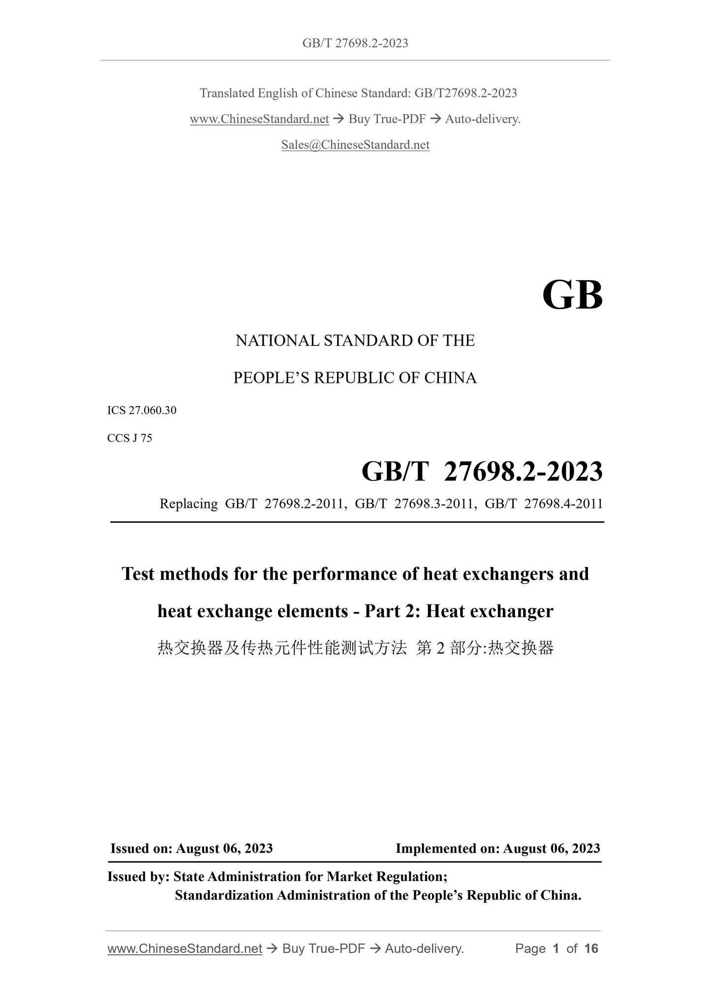
GB/T 27698.2-2023
GB
NATIONAL STANDARD OF THE
PEOPLE’S REPUBLIC OF CHINA
ICS 27.060.30
CCS J 75
Replacing GB/T 27698.2-2011, GB/T 27698.3-2011, GB/T 27698.4-2011
Test methods for the performance of heat exchangers and
heat exchange elements - Part 2: Heat exchanger
ISSUED ON: AUGUST 06, 2023
IMPLEMENTED ON: AUGUST 06, 2023
Issued by: State Administration for Market Regulation;
Standardization Administration of the People’s Republic of China.
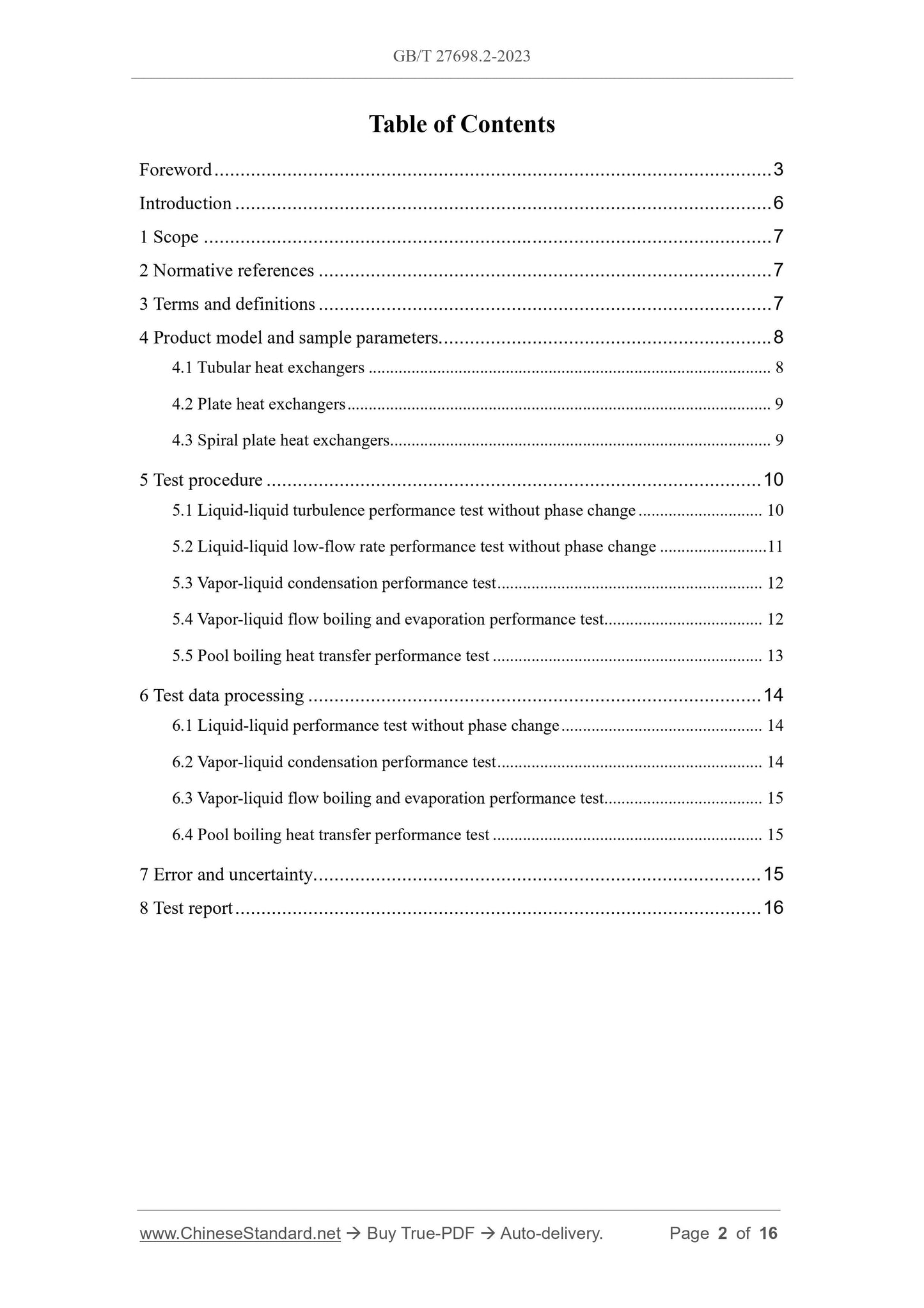
Table of Contents
Foreword ... 3
Introduction ... 6
1 Scope ... 7
2 Normative references ... 7
3 Terms and definitions ... 7
4 Product model and sample parameters... 8
4.1 Tubular heat exchangers ... 8
4.2 Plate heat exchangers ... 9
4.3 Spiral plate heat exchangers ... 9
5 Test procedure ... 10
5.1 Liquid-liquid turbulence performance test without phase change ... 10
5.2 Liquid-liquid low-flow rate performance test without phase change ... 11
5.3 Vapor-liquid condensation performance test ... 12
5.4 Vapor-liquid flow boiling and evaporation performance test ... 12
5.5 Pool boiling heat transfer performance test ... 13
6 Test data processing ... 14
6.1 Liquid-liquid performance test without phase change ... 14
6.2 Vapor-liquid condensation performance test ... 14
6.3 Vapor-liquid flow boiling and evaporation performance test ... 15
6.4 Pool boiling heat transfer performance test ... 15
7 Error and uncertainty ... 15
8 Test report ... 16
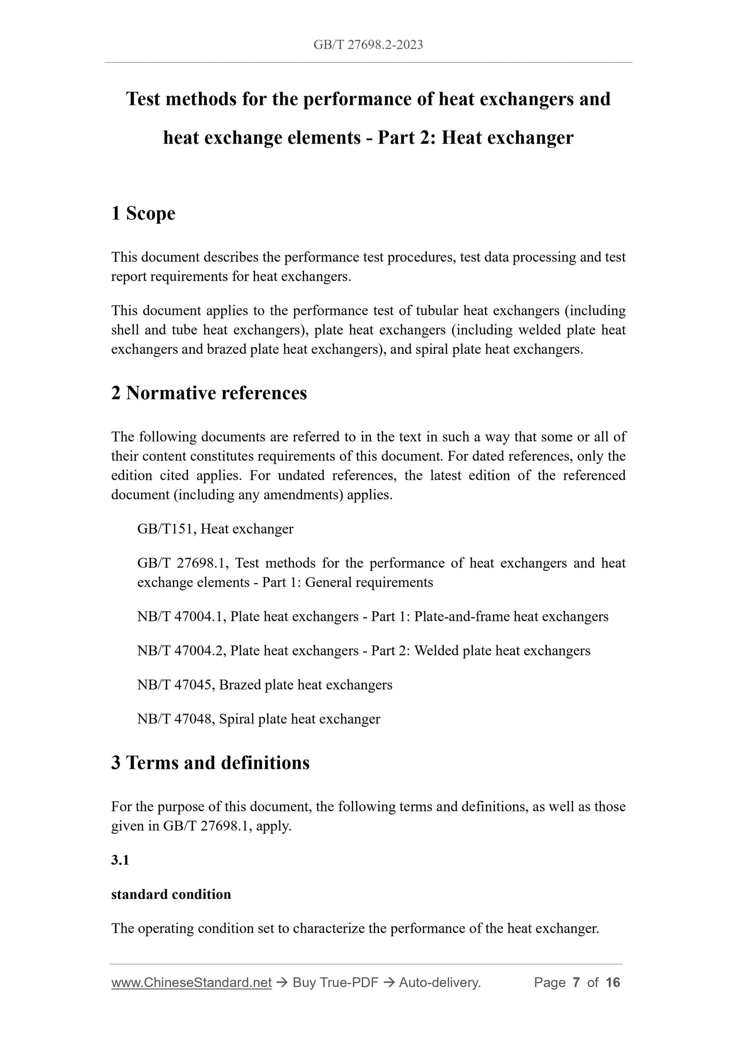
Test methods for the performance of heat exchangers and
heat exchange elements - Part 2: Heat exchanger
1 Scope
This document describes the performance test procedures, test data processing and test
report requirements for heat exchangers.
This document applies to the performance test of tubular heat exchangers (including
shell and tube heat exchangers), plate heat exchangers (including welded plate heat
exchangers and brazed plate heat exchangers), and spiral plate heat exchangers.
2 Normative references
The following documents are referred to in the text in such a way that some or all of
their content constitutes requirements of this document. For dated references, only the
edition cited applies. For undated references, the latest edition of the referenced
document (including any amendments) applies.
GB/T151, Heat exchanger
GB/T 27698.1, Test methods for the performance of heat exchangers and heat
exchange elements - Part 1: General requirements
NB/T 47004.1, Plate heat exchangers - Part 1: Plate-and-frame heat exchangers
NB/T 47004.2, Plate heat exchangers - Part 2: Welded plate heat exchangers
NB/T 47045, Brazed plate heat exchangers
NB/T 47048, Spiral plate heat exchanger
3 Terms and definitions
For the purpose of this document, the following terms and definitions, as well as those
given in GB/T 27698.1, apply.
3.1
standard condition
The operating condition set to characterize the performance of the heat exchanger.
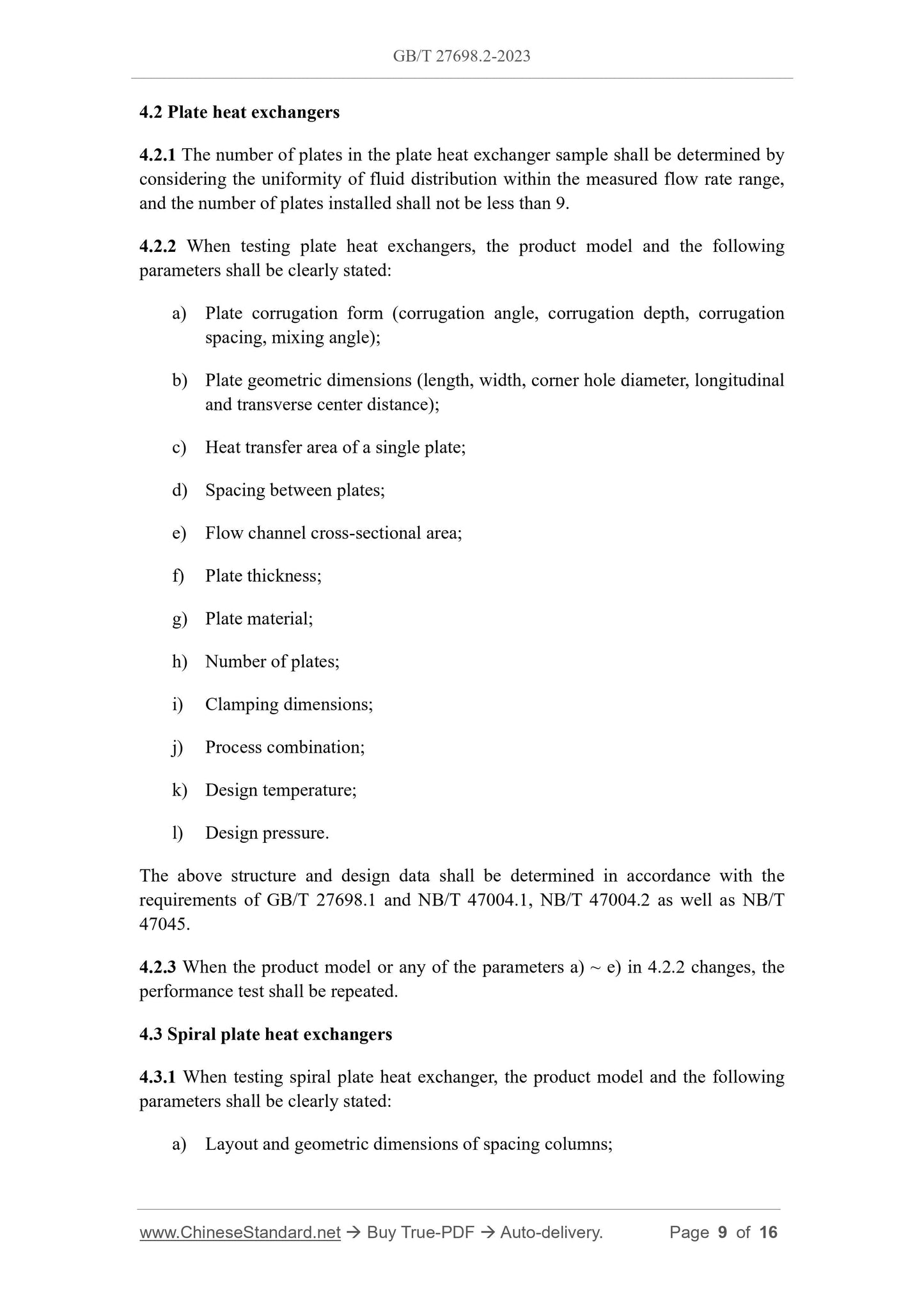
4.2 Plate heat exchangers
4.2.1 The number of plates in the plate heat exchanger sample shall be determined by
considering the uniformity of fluid distribution within the measured flow rate range,
and the number of plates installed shall not be less than 9.
4.2.2 When testing plate heat exchangers, the product model and the following
parameters shall be clearly stated:
a) Plate corrugation form (corrugation angle, corrugation depth, corrugation
spacing, mixing angle);
b) Plate geometric dimensions (length, width, corner hole diameter, longitudinal
and transverse center distance);
c) Heat transfer area of a single plate;
d) Spacing between plates;
e) Flow channel cross-sectional area;
f) Plate thickness;
g) Plate material;
h) Number of plates;
i) Clamping dimensions;
j) Process combination;
k) Design temperature;
l) Design pressure.
The above structure and design data shall be determined in accordance with the
requirements of GB/T 27698.1 and NB/T 47004.1, NB/T 47004.2 as well as NB/T
47045.
4.2.3 When the product model or any of the parameters a) ~ e) in 4.2.2 changes, the
performance test shall be repeated.
4.3 Spiral plate heat exchangers
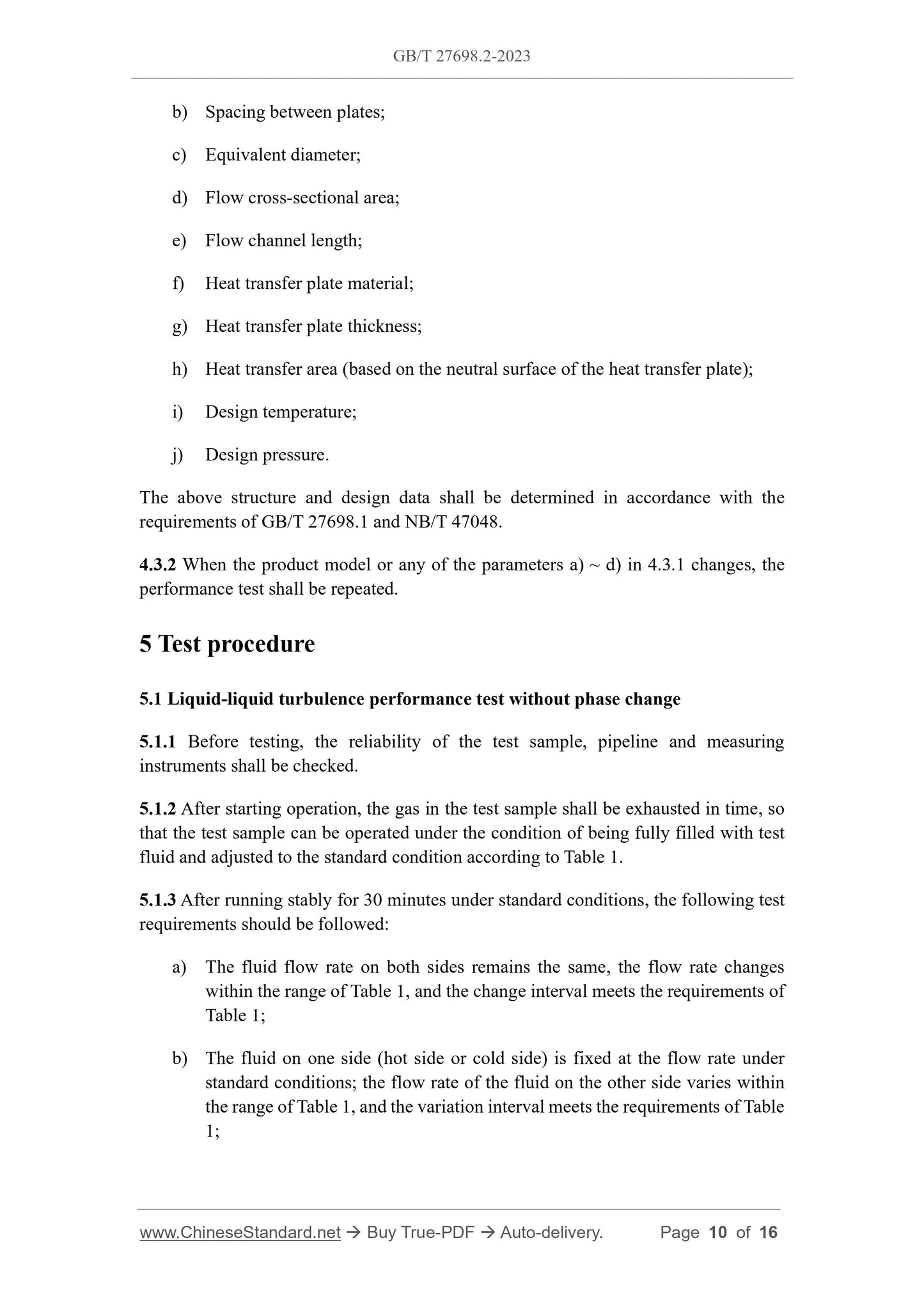
4.3.1 When testing spiral plate heat exchanger, the product model and the following
parameters shall be clearly stated:
a) Layout and geometric dimensions of spacing columns;
b) Spacing between plates;
c) Equivalent diameter;
d) Flow cross-sectional area;
e) Flow channel length;
f) Heat transfer plate material;
g) Heat transfer plate thickness;
h) Heat transfer area (based on the neutral surface of the heat transfer plate);
i) Design temperature;
j) Design pressure.
The above structure and design data shall be determined in accordance with the
requirements of GB/T 27698.1 and NB/T 47048.
4.3.2 When the product model or any of the parameters a) ~ d) in 4.3.1 changes, the
performance test shall be repeated.
5 Test procedure
5.1 Liquid-liquid turbulence performance test without phase change
5.1.1 Before testing, the reliability of the test sample, pipeline and measuring
instruments shall be checked.
5.1.2 After starting operation, the gas in the test sample shall be exhausted in time, so
that the test sample can be operated under the condition of being fully filled with test
fluid and adjusted to the standard condition according to Table 1.
5.1.3 After running stably for 30 minutes under standard conditions, the following test
requirements should be followed:
a) The fluid flow rate on both sides remains the same, the flow rate changes
within the range of Table 1, and the change interval meets the requirements of
Table 1;
b) The fluid on one side (hot side or cold side) is fixed at the flow rate under
standard conditions; the flow rate of the fluid on the other side varies within
the range of Table 1, and the variation interval meets the requirements of Table
1;
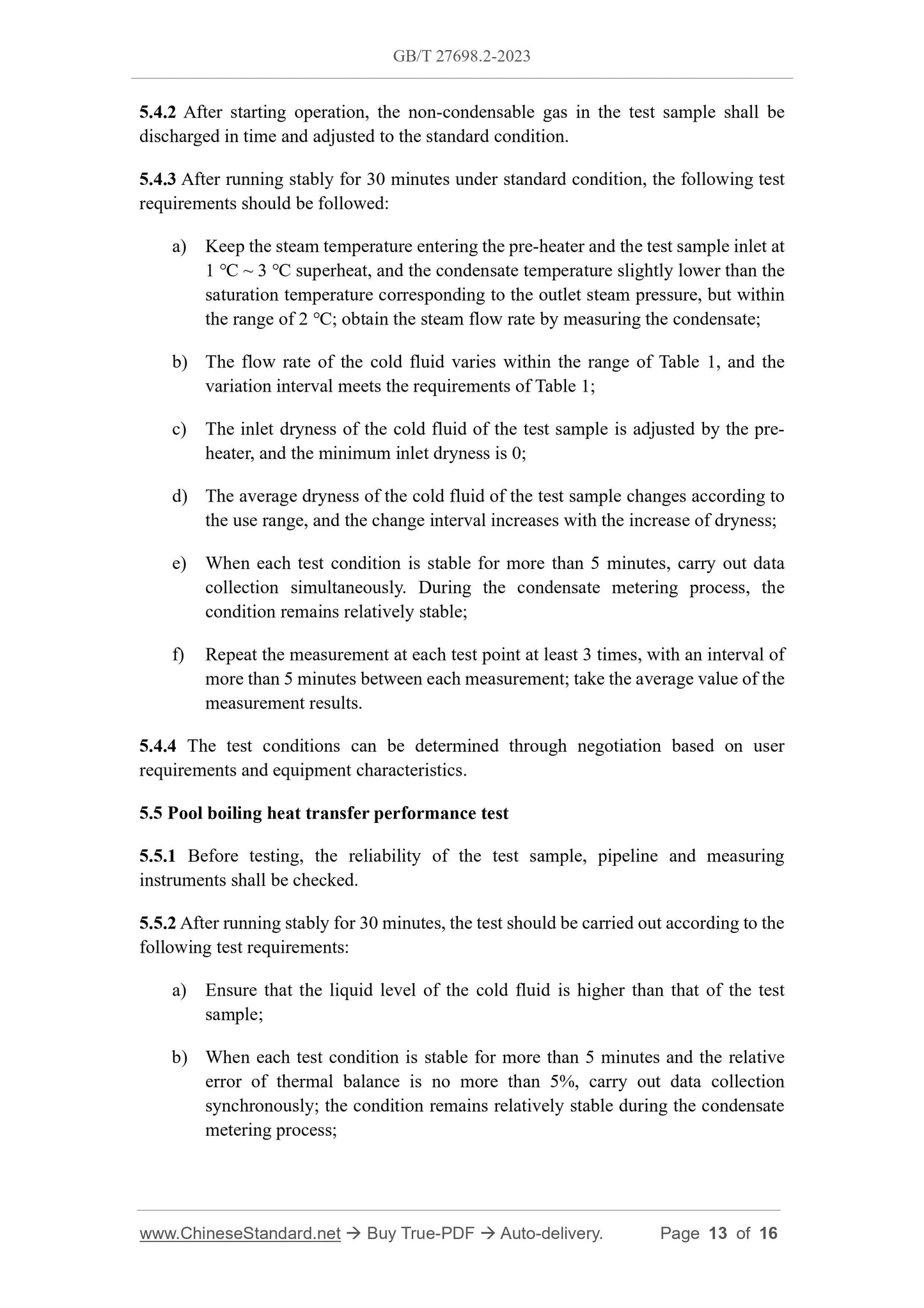
5.4.2 After starting operation, the non-condensable gas in the test sample shall be
discharged in time and adjusted to the standard condition.
5.4.3 After running stably for 30 minutes under standard condition, the following test
requirements should be followed:
a) Keep the steam temperature entering the pre-heater and the test sample inlet at
1 ℃ ~ 3 ℃ superheat, and the condensate temperature slightly lower than the
saturation temperature corresponding to the outlet steam pressure, but within
the range of 2 ℃; obtain the steam flow rate by measuring the condensate;
b) The flow rate of the cold fluid varies within the range of Table 1, and the
variation interval meets the requirements of Table 1;
c) The inlet dryness of the cold fluid of the test sample is adjusted by the pre-
heater, and the minimum inlet dryness is 0;
d) The average dryness of the cold fluid of the test sample changes according to
the use range, and the change interval increases with the increase of dryness;
e) When each test condition is stable for more than 5 minutes, carry out data
collection simultaneously. During the condensate metering process, the
condition remains relatively stable;
f) Repeat the measurement at each test point at least 3 times, with an interval of
more than 5 minutes between each measurement; take the average value of the
measurement results.
5.4.4 The test conditions can be determined through negotiation based on user
requirements and equipment characteristics.
5.5 Pool boiling heat transfer performance test
5.5.1 Before testing, the reliability of the test sample, pipeline and measuring
instruments shall be checked.
5.5.2 After running stably for 30 minutes, the test should be carried out according to the
following test requirements:
a) Ensure that the liquid level of the cold fluid is higher than that of the test
sample;
b) When each test condition is stable for more than 5 minutes and the relative
error of thermal balance is no more than 5%, carry out data collection
synchronously; the condition remains relatively stable during the condensate
metering process;
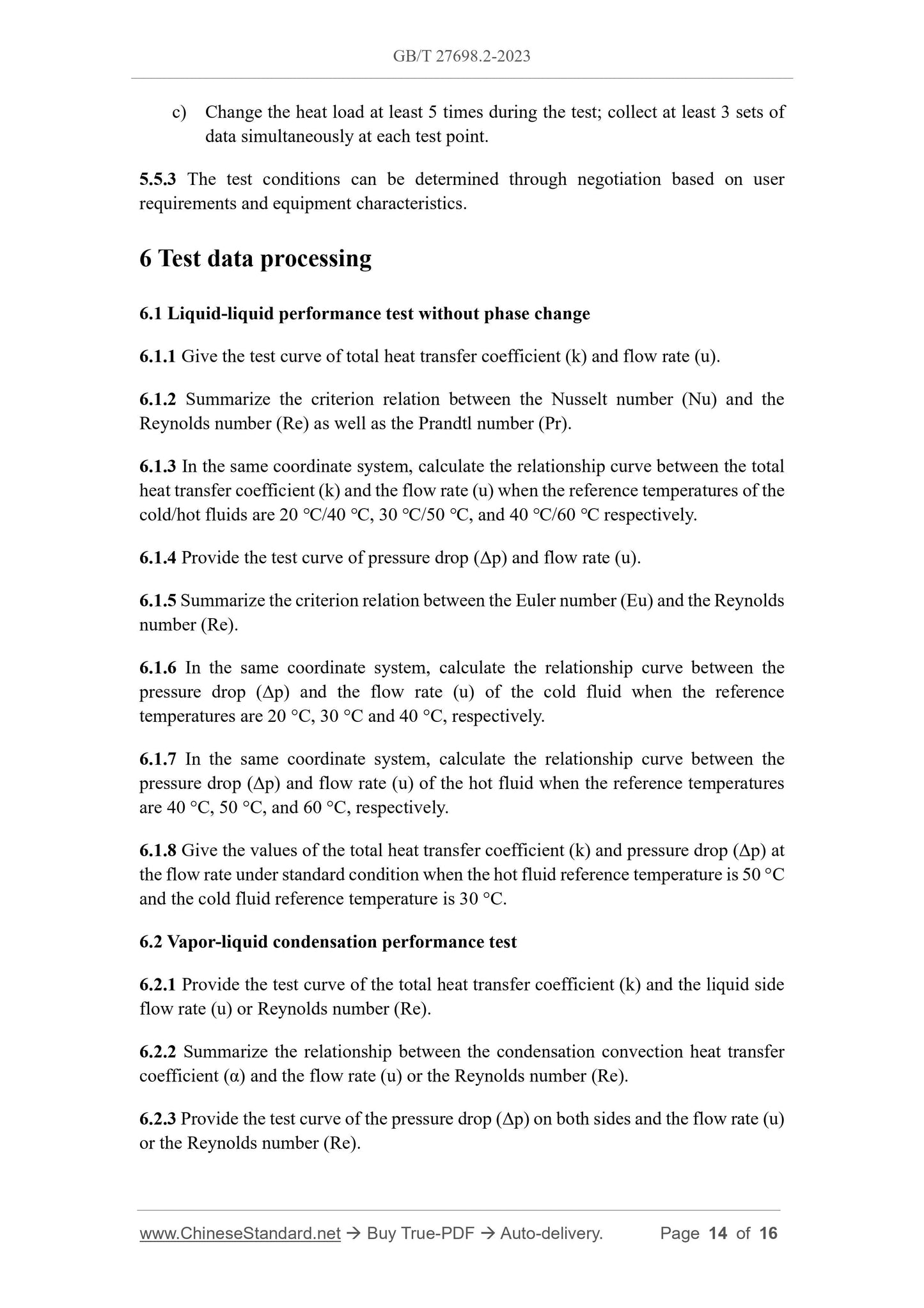
c) Change the heat load at least 5 times during the test; collect at least 3 sets of
data simultaneously at each test point.
5.5.3 The test conditions can be determined through negotiation based on user
requirements and equipment characteristics.
6 Test data processing
6.1 Liquid-liquid performance test without phase change
6.1.1 Give the test curve of total heat transfer coefficient (k) and flow rate (u).
6.1.2 Summarize the criterion relation between the Nusselt number (Nu) and the
Reynolds number (Re) as well as the Prandtl number (Pr).
6.1.3 In the same coordinate system, calculate the relationship curve between the total
heat transfer coefficient (k) and the flow rate (u) when the reference temperatures of the
cold/hot fluids are 20 ℃/40 ℃, 30 ℃/50 ℃, and 40 ℃/60 ℃ respectively.
6.1.4 Provide the test curve of pressure drop (Δp) and flow rate (u).
6.1.5 Summarize the criterion relation between the Euler number (Eu) and the Reynolds
number (Re).
6.1.6 In the same coordinate system, calculate the relationship curve between the
pressure drop (Δp) and the flow rate (u) of the cold fluid when the reference
temperatures are 20 °C, 30 °C and 40 °C, respectively.
6.1.7 In the same coordinate system, calculate the relationship curve between the
pressure drop (Δp) and flow rate (u) of the hot fluid when the reference temperatures
are 40 °C, 50 °C, and 60 °C, respectively.
6.1.8 Give the values of the total heat transfer coefficient (k) and pressure drop (Δp) at
the flow rate under standard condition when the hot fluid reference temperature is 50 °C
and the cold fluid reference temperature is 30 °C.
6.2 Vapor-liquid condensation performance test
6.2.1 Provide the test curve of the total heat transfer coefficient (k) and the liquid side
flow rate (u) or Reynolds number (Re).
6.2.2 Summarize the relationship between the condensation convection heat transfer
coefficient (α) and the flow rate (u) or the Reynolds number (Re).
6.2.3 Provide the test curve of the pressure drop (Δp) on both sides and the flow rate (u)
or the Reynolds number (Re).
GB/T 27698.2-2023
GB
NATIONAL STANDARD OF THE
PEOPLE’S REPUBLIC OF CHINA
ICS 27.060.30
CCS J 75
Replacing GB/T 27698.2-2011, GB/T 27698.3-2011, GB/T 27698.4-2011
Test methods for the performance of heat exchangers and
heat exchange elements - Part 2: Heat exchanger
ISSUED ON: AUGUST 06, 2023
IMPLEMENTED ON: AUGUST 06, 2023
Issued by: State Administration for Market Regulation;
Standardization Administration of the People’s Republic of China.
Table of Contents
Foreword ... 3
Introduction ... 6
1 Scope ... 7
2 Normative references ... 7
3 Terms and definitions ... 7
4 Product model and sample parameters... 8
4.1 Tubular heat exchangers ... 8
4.2 Plate heat exchangers ... 9
4.3 Spiral plate heat exchangers ... 9
5 Test procedure ... 10
5.1 Liquid-liquid turbulence performance test without phase change ... 10
5.2 Liquid-liquid low-flow rate performance test without phase change ... 11
5.3 Vapor-liquid condensation performance test ... 12
5.4 Vapor-liquid flow boiling and evaporation performance test ... 12
5.5 Pool boiling heat transfer performance test ... 13
6 Test data processing ... 14
6.1 Liquid-liquid performance test without phase change ... 14
6.2 Vapor-liquid condensation performance test ... 14
6.3 Vapor-liquid flow boiling and evaporation performance test ... 15
6.4 Pool boiling heat transfer performance test ... 15
7 Error and uncertainty ... 15
8 Test report ... 16
Test methods for the performance of heat exchangers and
heat exchange elements - Part 2: Heat exchanger
1 Scope
This document describes the performance test procedures, test data processing and test
report requirements for heat exchangers.
This document applies to the performance test of tubular heat exchangers (including
shell and tube heat exchangers), plate heat exchangers (including welded plate heat
exchangers and brazed plate heat exchangers), and spiral plate heat exchangers.
2 Normative references
The following documents are referred to in the text in such a way that some or all of
their content constitutes requirements of this document. For dated references, only the
edition cited applies. For undated references, the latest edition of the referenced
document (including any amendments) applies.
GB/T151, Heat exchanger
GB/T 27698.1, Test methods for the performance of heat exchangers and heat
exchange elements - Part 1: General requirements
NB/T 47004.1, Plate heat exchangers - Part 1: Plate-and-frame heat exchangers
NB/T 47004.2, Plate heat exchangers - Part 2: Welded plate heat exchangers
NB/T 47045, Brazed plate heat exchangers
NB/T 47048, Spiral plate heat exchanger
3 Terms and definitions
For the purpose of this document, the following terms and definitions, as well as those
given in GB/T 27698.1, apply.
3.1
standard condition
The operating condition set to characterize the performance of the heat exchanger.
4.2 Plate heat exchangers
4.2.1 The number of plates in the plate heat exchanger sample shall be determined by
considering the uniformity of fluid distribution within the measured flow rate range,
and the number of plates installed shall not be less than 9.
4.2.2 When testing plate heat exchangers, the product model and the following
parameters shall be clearly stated:
a) Plate corrugation form (corrugation angle, corrugation depth, corrugation
spacing, mixing angle);
b) Plate geometric dimensions (length, width, corner hole diameter, longitudinal
and transverse center distance);
c) Heat transfer area of a single plate;
d) Spacing between plates;
e) Flow channel cross-sectional area;
f) Plate thickness;
g) Plate material;
h) Number of plates;
i) Clamping dimensions;
j) Process combination;
k) Design temperature;
l) Design pressure.
The above structure and design data shall be determined in accordance with the
requirements of GB/T 27698.1 and NB/T 47004.1, NB/...
View full details