GB/T 26949.11-2016 English PDF (GBT26949.11-2016)
Regular price
$150.00 USD
Regular price
Sale price
$150.00 USD
Unit price
/
per
Delivery: 3 seconds. Download true-PDF + Invoice.
Get QUOTATION in 1-minute: Click GB/T 26949.11-2016
Historical versions: GB/T 26949.11-2016
Preview True-PDF (Reload/Scroll if blank)
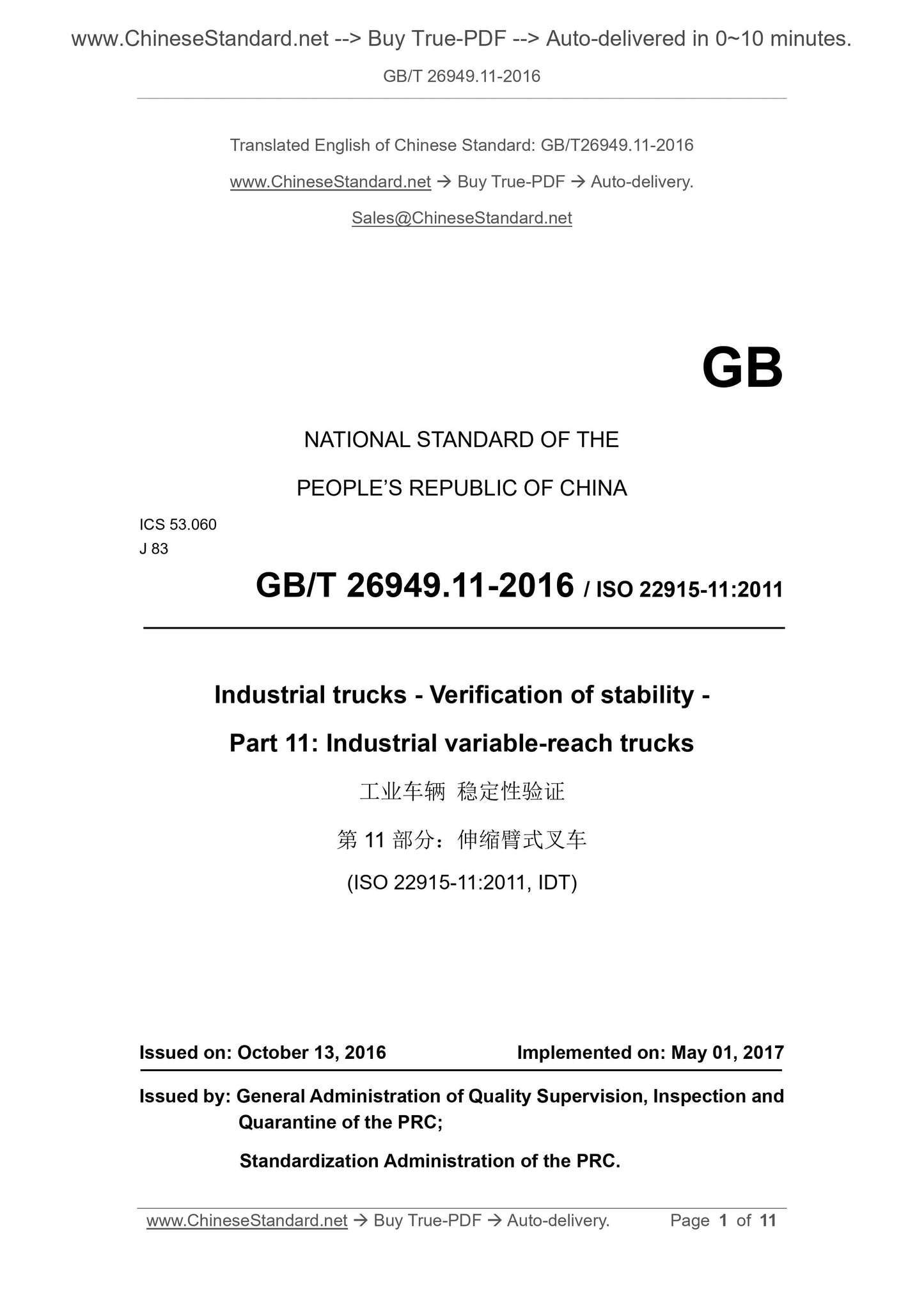
GB/T 26949.11-2016: Industrial trucks -- Verification of stability -- Part 11: Industrial variable-reach trucks
GB/T 26949.11-2016
Industrial trucks--Verification of stability--Part 11. Industrial variable-reach trucks
ICS 53.060
J83
National Standards of People's Republic of China
Industrial vehicle stability verification
Part 11. Telescopic forklift
(ISO 22915-11.2011, IDT)
Released on October 13,.2016
2017-05-01 implementation
General Administration of Quality Supervision, Inspection and Quarantine of the People's Republic of China
China National Standardization Administration issued
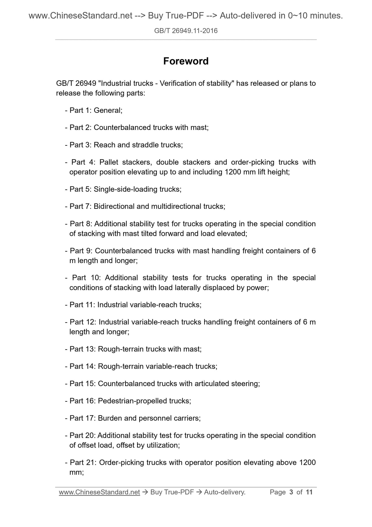
Foreword
GB/T 26949 "Industrial Vehicle Stability Verification" has or plans to release the following parts.
--- Part 1. General;
---Part 2. Counterbalanced forklift;
--- Part 3. Forward and legged forklifts;
--- Part 4. Pallet stacker, double stacker and picker with a height of not more than 1200mm from the operator;
--- Part 5. Side forklifts (one side);
--- Part 7. Two-way and multi-directional operation of the forklift;
--- Part 8. Additional stability tests for stacking operations under gantry forward and load lift conditions;
---Part 9. Counterbalanced forklifts carrying freight containers of 6m and longer lengths;
--- Part 10. Additional stability tests for stacking operations under lateral load conditions of power units;
--- Part 11. Telescopic forklift;
--- Part 12. Telescopic forklifts carrying freight containers of 6 m or longer in length;
--- Part 13. Off-road forklifts with gantry;
--- Part 14. Off-road telescopic forklift;
--- Part 15. Counterbalanced forklifts with articulated steering;
--- Part 16. Walker vehicles;
--- Part 17. Cargo and personnel carriers;
--- Part 20. Additional stability tests for operation under load bias conditions;
--- Part 21. Picking vehicles with an operator position elevation greater than 1200 mm;
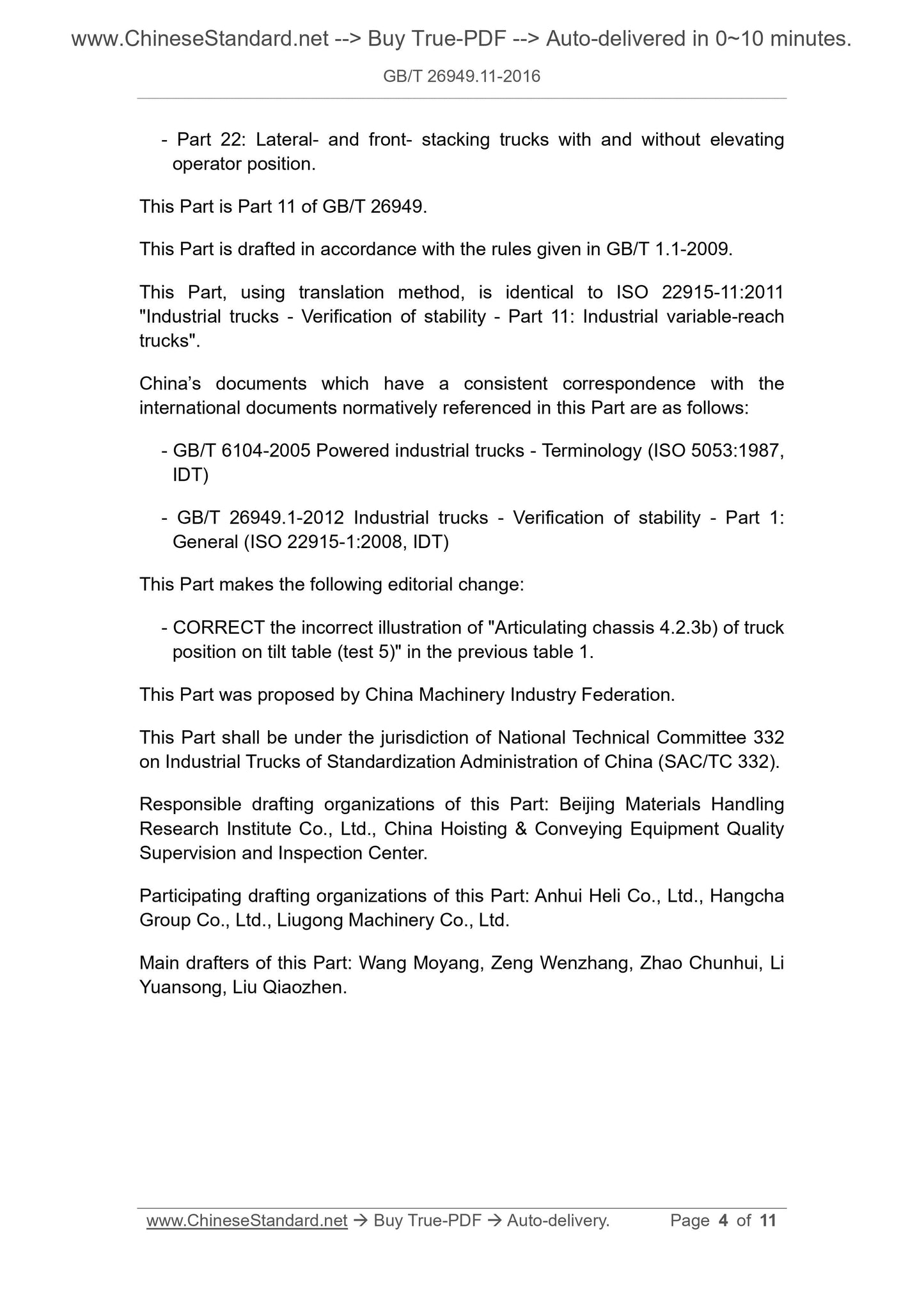
--- Part 22. Three-way stacker forklifts with or without operator position.
This part is the 11th part of GB/T 26949.
This part is drafted in accordance with the rules given in GB/T 1.1-2009.
This section uses the translation method equivalent to ISO 22915-11.2011 "Industrial Vehicle Stability Verification Part 11. Telescopic Arms
car".
The documents of our country that have a consistent correspondence with the international documents referenced in this part are as follows.
---GB/T 6104-2005 Mobile Industrial Vehicle Terminology (ISO 5053.1987, IDT)
--- GB/T 26949.1-2012 Industrial vehicle stability verification Part 1. General (ISO 22915-1.2008, IDT)
This section has made the following editorial changes.
--- Original Table 1 "The position of the vehicle on the inclined platform (Test 5) in the articulated frame 4.2.3b)" is incorrect and corrected.
This part was proposed by the China Machinery Industry Federation.
This part is under the jurisdiction of the National Industrial Vehicle Standardization Technical Committee (SAC/TC332).
This section is responsible for drafting units. Beijing Crane Transportation Machinery Design and Research Institute, National Lifting and Transportation Machinery Quality Supervision and Inspection Center.
Participated in the drafting of this section. Anhui Heli Co., Ltd., Hangcha Group Co., Ltd., Guangxi Liugong Machinery Co., Ltd.
the company.
The main drafters of this section. Wang Moyang, Zeng Wen, Zhao Chunhui, Li Yuansong, Liu Qiaozhen.
Industrial vehicle stability verification
Part 11. Telescopic forklift
1 Scope
This part of GB/T 26949 specifies the test method for verifying the stability of telescopic forklift trucks equipped with forks or load handling attachments.
This section does not apply to vehicles designed to carry freight containers and off-road telescopic forklifts as specified in ISO 22915-14.
2 Normative references
The following documents are indispensable for the application of this document. For dated references, only dated versions apply to this article.
Pieces. For undated references, the latest edition (including all amendments) applies to this document.
ISO 3691-2 Safety requirements and verification of industrial vehicles - Part 2. Self-propelled telescopic forklifts (Industrytruck-
Safetyrequirementandverification-Part 2. Self-propeledvariable-reachtrucks)
ISO 5053 Mobile Industrial Vehicle Terminology (Poweredindustrialtrucks-Terminology)
ISO 22915-1 - Determination of stability of industrial vehicles - Part 1. General (Industrialtrucks-Verification of
stability-Part 1.General)
3 Terms and definitions
The following terms and definitions defined by ISO 3691-2 and ISO 22915-1 apply to this document.
3.1
Telescopic forklift variable-reachtruck
With retractable (or non-retractable), non-rotatable as defined in ISO 5053 or on either side of the longitudinal axis of the vehicle
An articulated arm that does not exceed 5°, a counterweight lift truck for load stacking.
Note 1. The load handling device can be fixed directly to the hoisting mechanism or to the sub-gantry mounted at the end of the hoisting mechanism.
Note 2. Telescopic forklifts can be equipped with integral or articulated frames, stabilizers, axle locking devices as defined in ISO 3691-2 or horizontally leveling of the frame
Device, or 2-wheel/4-wheel steering or articulated frame steering system.
3.2
Industrial telescopic forklift industrialvariable-reachtruck
Designed for telescopic forklifts that work on solid, level, level and paved surfaces.
4 test conditions
4.1 General
See ISO 22915-1.
4.2 Location of the vehicle on the inclined platform
4.2.1 Load bridge and steering axle
Figure 1 defines the load bridge/drive axle and steering axle of the vehicle.
Description.
AA---the longitudinal center plane of the vehicle;
BB --- steering axle (rear axle);
CC --- load bridge/drive axle.
Note. The load bridge/drive axle of a 4-wheel steering vehicle is also a steering axle.
Figure 1 Load bridge and steering bridge
4.2.2 Test 1 and Test 2
The vehicle should be placed on a tilting platform whose steering axle BB and load bridge CC should be parallel to the tilting axis XY of the tilting platform.
See Table 1.
4.2.3 Test 3, Test 4 and Test 5
The vehicle should be placed on the inclined platform in a turned state such that the MN line is parallel to the tilt axis XY of the tilting platform, see Table 1.
For vehicles with articulated steering axles, the wheels on the steering axle near the XY side of the tilt axis should be parallel to XY, see Table 1.
The definition of point M is as follows.
a) For vehicles with articulated steering axles. point M is the intersection of the longitudinal center plane AA of the vehicle and the axis of the steering axle.
The projection on the stage, see Table 1;
b) For vehicles with articulated frames. point M is the intersection of the longitudinal center plane JJ of the rear frame and the fully articulated rear axle axis
Projection on the inclined platform, see Table 1;
c) For vehicles with axle locking devices. point M refers to the contact of the rear wheel closest to the tilting axis XY on the inclined platform
The center point of the face is shown in Table 1.
As shown in Table 1, point N is defined as the contact of the load wheel (or stabilizer, if fitted) closest to the tilt axis XY on the inclined platform.
The center point.
4.3 Test load
When conducting tests 1 and 3, the boom with the test load should be in a lifting and extending group that is most detrimental to vehicle stability.
In the combined state, the fork level is also at the same time.
When conducting test 5, the boom should be at the maximum lifting angle and in the maximum and minimum overhang conditions, respectively, and the ...