Skip to product information
1 of 7

PayPal, credit cards. Download editable-PDF and invoice in 1 second!

GB/T 26773-2011 English PDF (GBT26773-2011)

GB/T 26773-2011 English PDF (GBT26773-2011)

Regular price $145.00 USD
Regular price Sale price $145.00 USD
Sale Sold out
Shipping calculated at checkout.
Quotation: In 1-minute, 24-hr self-service. Click here GB/T 26773-2011 to get it for Purchase Approval, Bank TT...

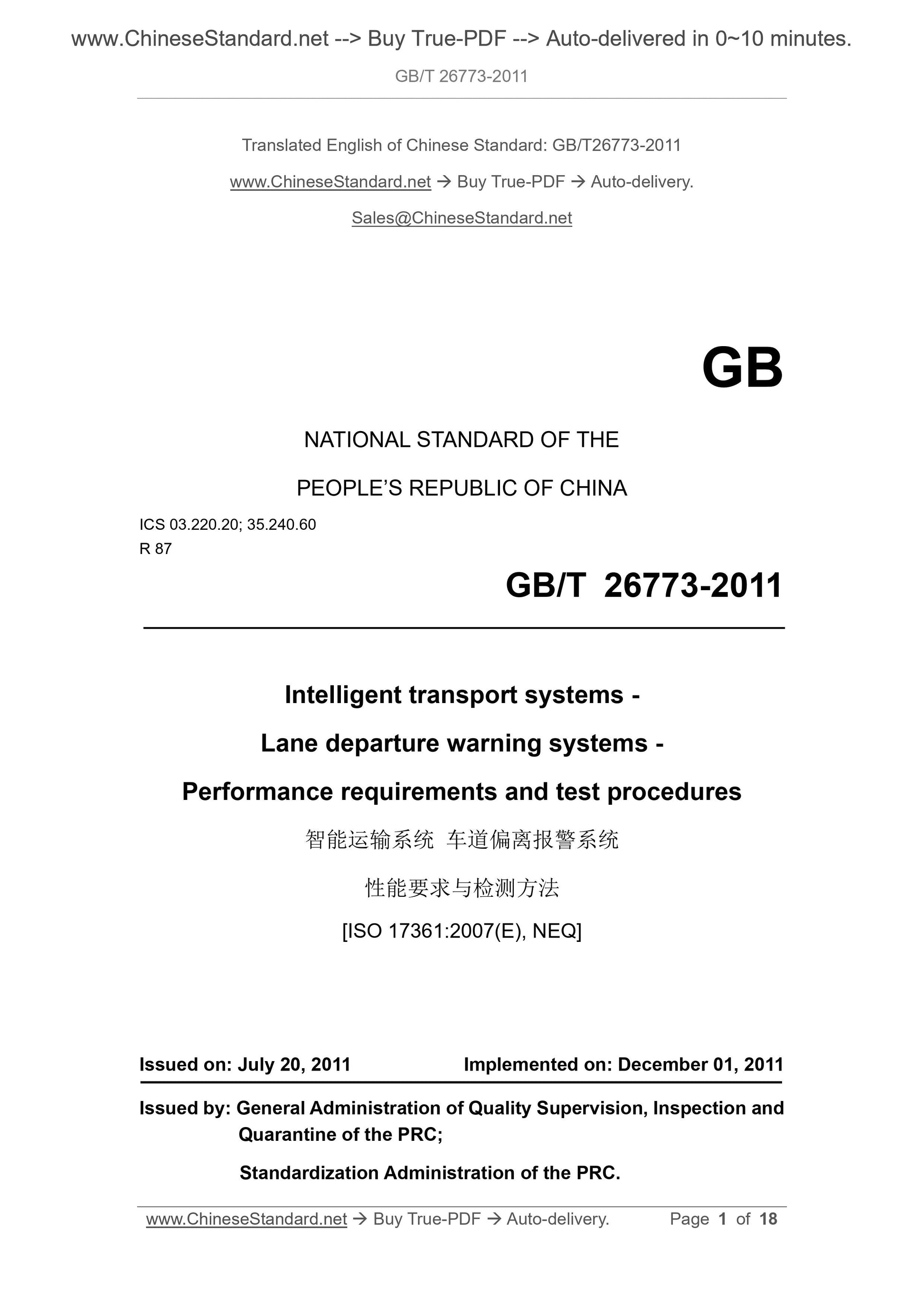
GB/T 26773-2011: Intelligent transport systems -- Lane departure warning systems -- Performance requirements and test procedures

This Standard specifies the definitions, classification, functions, human machine interface (HMI), and test procedures, etc. of lane departure warning systems. This Standard applies to passenger cars and commercial vehicles. It is not applicable to warnings on road sections with temporary or irregular lane markings (such as road construction areas).
GB/T 26773-2011
NATIONAL STANDARD OF THE
PEOPLE’S REPUBLIC OF CHINA
ICS 03.220.20; 35.240.60
R 87
Intelligent transport systems -
Lane departure warning systems -
Performance requirements and test procedures
[ISO 17361:2007(E), NEQ]
ISSUED ON: JULY 20, 2011
IMPLEMENTED ON: DECEMBER 01, 2011
Issued by: General Administration of Quality Supervision, Inspection and Quarantine of the PRC;
Standardization Administration of the PRC.
Table of Contents
Foreword ... 3
Introduction ... 4
1 Scope ... 5
2 Normative references ... 5
3 Terms and definitions ... 5
4 Technical requirements ... 10
5 Test procedures ... 14
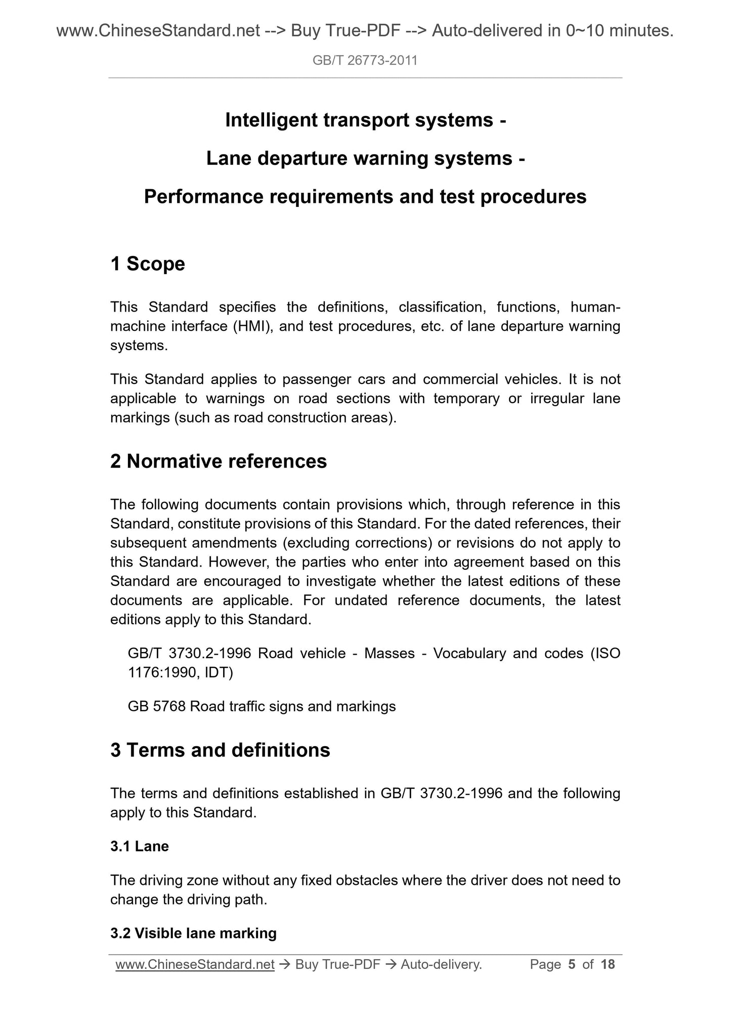
Intelligent transport systems -
Lane departure warning systems -
Performance requirements and test procedures
1 Scope
This Standard specifies the definitions, classification, functions, human- machine interface (HMI), and test procedures, etc. of lane departure warning systems.
This Standard applies to passenger cars and commercial vehicles. It is not applicable to warnings on road sections with temporary or irregular lane markings (such as road construction areas).
2 Normative references
The following documents contain provisions which, through reference in this Standard, constitute provisions of this Standard. For the dated references, their subsequent amendments (excluding corrections) or revisions do not apply to this Standard. However, the parties who enter into agreement based on this Standard are encouraged to investigate whether the latest editions of these documents are applicable. For undated reference documents, the latest
editions apply to this Standard.
GB/T 3730.2-1996 Road vehicle - Masses - Vocabulary and codes (ISO
1176:1990, IDT)
GB 5768 Road traffic signs and markings
3 Terms and definitions
The terms and definitions established in GB/T 3730.2-1996 and the following apply to this Standard.
3.1 Lane
The driving zone without any fixed obstacles where the driver does not need to change the driving path.
3.2 Visible lane marking
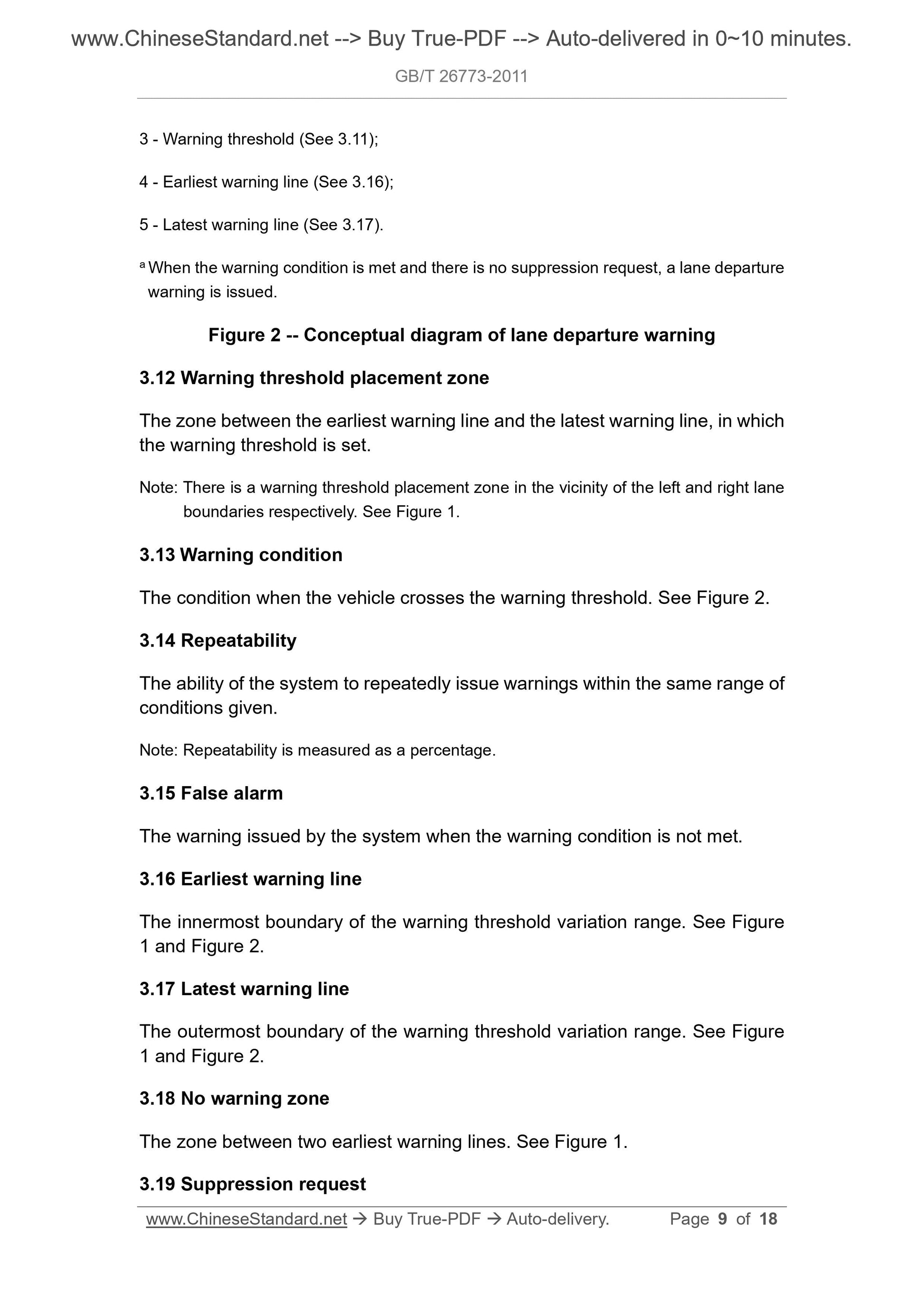
3 - Warning threshold (See 3.11);
4 - Earliest warning line (See 3.16);
5 - Latest warning line (See 3.17).
a When the warning condition is met and there is no suppression request, a lane departure warning is issued.
Figure 2 -- Conceptual diagram of lane departure warning
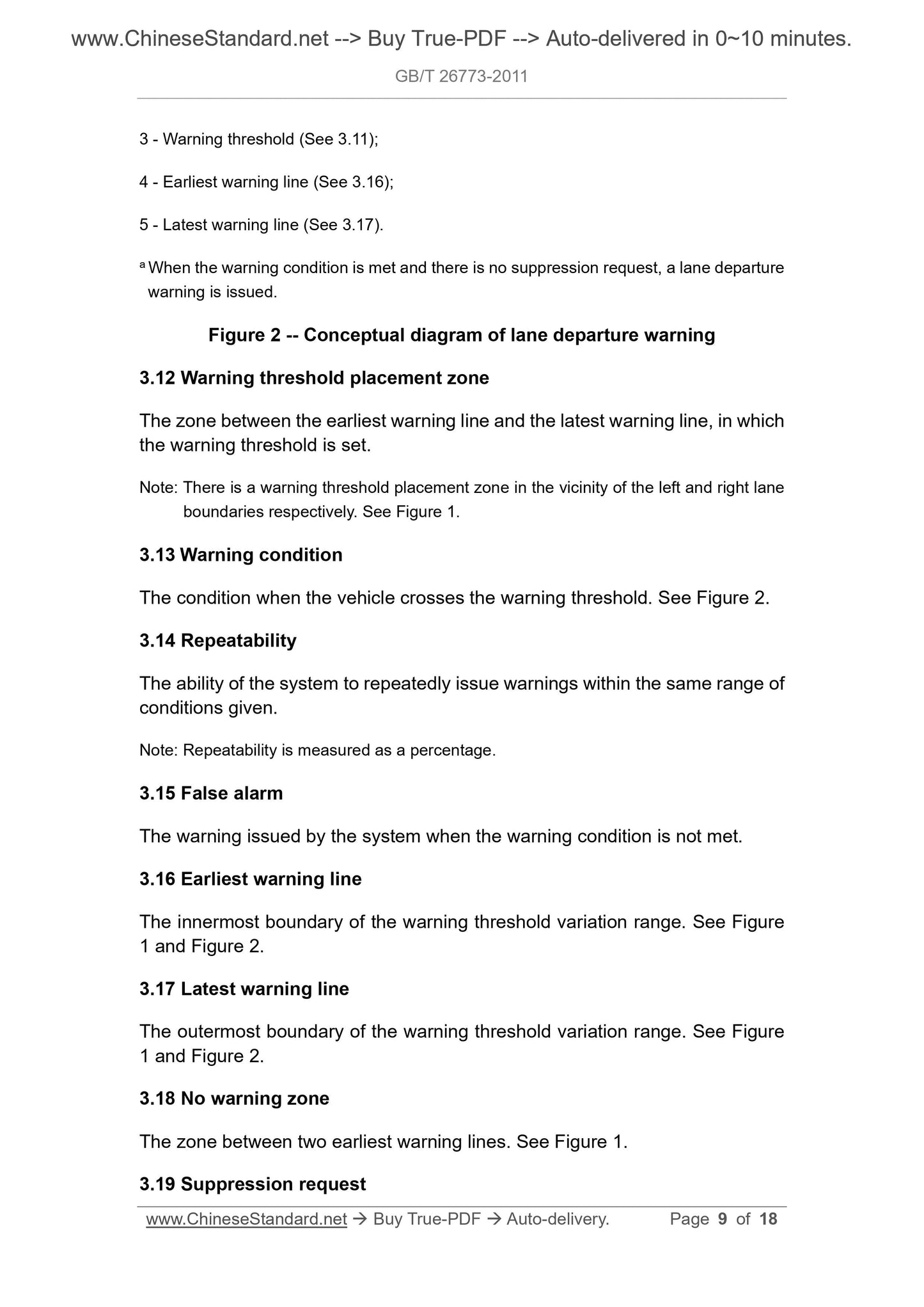
3.12 Warning threshold placement zone
The zone between the earliest warning line and the latest warning line, in which the warning threshold is set.
Note: There is a warning threshold placement zone in the vicinity of the left and right lane boundaries respectively. See Figure 1.
3.13 Warning condition
The condition when the vehicle crosses the warning threshold. See Figure 2. 3.14 Repeatability
The ability of the system to repeatedly issue warnings within the same range of conditions given.
Note: Repeatability is measured as a percentage.
3.15 False alarm
The warning issued by the system when the warning condition is not met. 3.16 Earliest warning line
The innermost boundary of the warning threshold variation range. See Figure 1 and Figure 2.
3.17 Latest warning line
The outermost boundary of the warning threshold variation range. See Figure 1 and Figure 2.
3.18 No warning zone
The zone between two earliest warning lines. See Figure 1.
3.19 Suppression request
An ability to disable the system from issuing a warning based on driver requests or system functions when it is detected that the driver intends to deviate from the lane. See Figure 2.
3.20 Lane departure warning
A warning issued to the driver due to meeting the lane departure warning condition without a suppression request. See Figure 2.
3.21 System incapable
A status in which the system cannot warn the lane departure due to the
influence of sudden conditions.
3.22 Status indication
An indication for the current status of the system, such as on or off, fault, incapable, etc.
3.23 Haptic warning
A warning which can give the driver stimuli such as touch, vibration, pressure, and movement, such as steering wheel movement, steering wheel vibration, seat and foot pedal vibration, etc.
3.24 Curve cutting
Driving behavior towards the inside of curve which may lead to intentional lane departures.
3.25 Visibility; meteorological optical range
The distance through which the luminous flux of a parallel beam emitted by an incandescent lamp with a color temperature of 2700 K is attenuated to 5% of the initial value in the atmosphere.
4 Technical requirements
4.1 System functions
The functional composition of lane departure warning systems is illustrated in Figure 3. Where suppression request, vehicle speed measurement, driver
preferences, and other additional functions are optional.
4.3.4.2 The system may detect the suppression request signal, to minimize unnecessary warnings. For example, when the driver is performing steering, braking, or other higher-priority operations such as collision avoidance operation, the system suppression request is in effect.
4.3.4.3 When the warning is suppressed, the system may notify the driver. 4.3.4.4 The system may measure the speed of the vehicle, so as to support other functions, such as suppressing warning when the speed of the vehicle is lower than the speed specified in 4.3.2.6.
4.3.4.5 When there is a visible marking on only one side of the lane, the system can use the default lane width to establish a virtual marking on the other side of the lane for warning; or directly alert the driver to the system incapable. 4.3.4.6 The position of warning threshold may be adjusted within the warning threshold placement zone.
4.3.4.7 During the curve driving, considering the curve cutting operation behavior, the system will move the position of warning threshold outward, but never exceed the latest warning line.
4.3.4.8 If only haptic warning and (or) audible warning modes are used, the warning may be designed to have the function of indicating the vehicle’s departure direction (For example, the means such as position of sound source, direction of motion may be used). Otherwise, it is necessary to use visual information to assist the warning.
4.3.4.9 The system may suppress additional warnings, to avoid annoying the driver due to excessive warning information.
5 Test procedures
5.1 Test environmental conditions
It shall use the following test environmental conditions.
a) Test location: Dry and flat asphalt or concrete pavement;
b) Range of test temperature: -20 °C~40 °C;
c) The visible lane markings on the test road surface shall be in good
condition and in accordance with the provisions of GB 5768.
d) The horizontal visibility shall be greater than 1 km.
5.2 Test lane conditions
The radius of curvature of the test lane shall be within ±10% of the minimum radius of curvature of the corresponding type in Table 1. The test lane shall be of sufficient length, to meet the needs of the minimum operating speed (i.e. Type I 17 m/s, Type II 20 m/s), so that the vehicle can, at a rate of departure of 0 m/s< v≤0.8 m/s, leave the lane.
5.3 Test vehicle conditions
The mass of the test vehicle shall be BETWEEN the total of complete vehicle kerb mass plus the mass of driver and test equipment (The total mass of the driver and test equipment does not exceed 150 kg) AND the maximum
allowable total mass. The mass description shall comply with the requirements of 3.2 of GB/T 3730.2-1996. After the start of the test, it is not allowed to change the conditions of the test vehicle.
5.4 Installation and setup of test system
Installation and setup of lane departure warning systems shall be performed in accordance with the equipment instructions provided by the manufacturer. For the test of lane departure warning systems with user-adjustable warning threshold, it shall perform each test twice; that is, the warning threshold is set at the earliest warning line once and set at the latest warning line once. After the start of the test, it is not allowed to change the system setup.
5.5 Test procedures
5.5.1 Parameters obtained from data record
The following are the parameters obtained from the data record:
a) Warning issue point (time and/or space);
b) Rate of departure;
c) Vehicle speed.
The test equipment records all warning information during the test and obtains the required parameters from it. Data shall be recorded by the test equipment and shall not be recorded by the system itself. The test report shall indicate the precision of the test equipment itself.
5.5.2 Procedures
5.5.2.1 It shall complete the following three tests:

View full details