Skip to product information
1 of 7

PayPal, credit cards. Download editable-PDF and invoice in 1 second!

GB/T 2625-1981 English PDF (GBT2625-1981)

GB/T 2625-1981 English PDF (GBT2625-1981)

Regular price $150.00 USD
Regular price Sale price $150.00 USD
Sale Sold out
Shipping calculated at checkout.
Delivery: 3 seconds. Download true-PDF + Invoice.
Get QUOTATION in 1-minute: Click GB/T 2625-1981
Historical versions: GB/T 2625-1981
Preview True-PDF (Reload/Scroll if blank)

GB/T 2625-1981: 
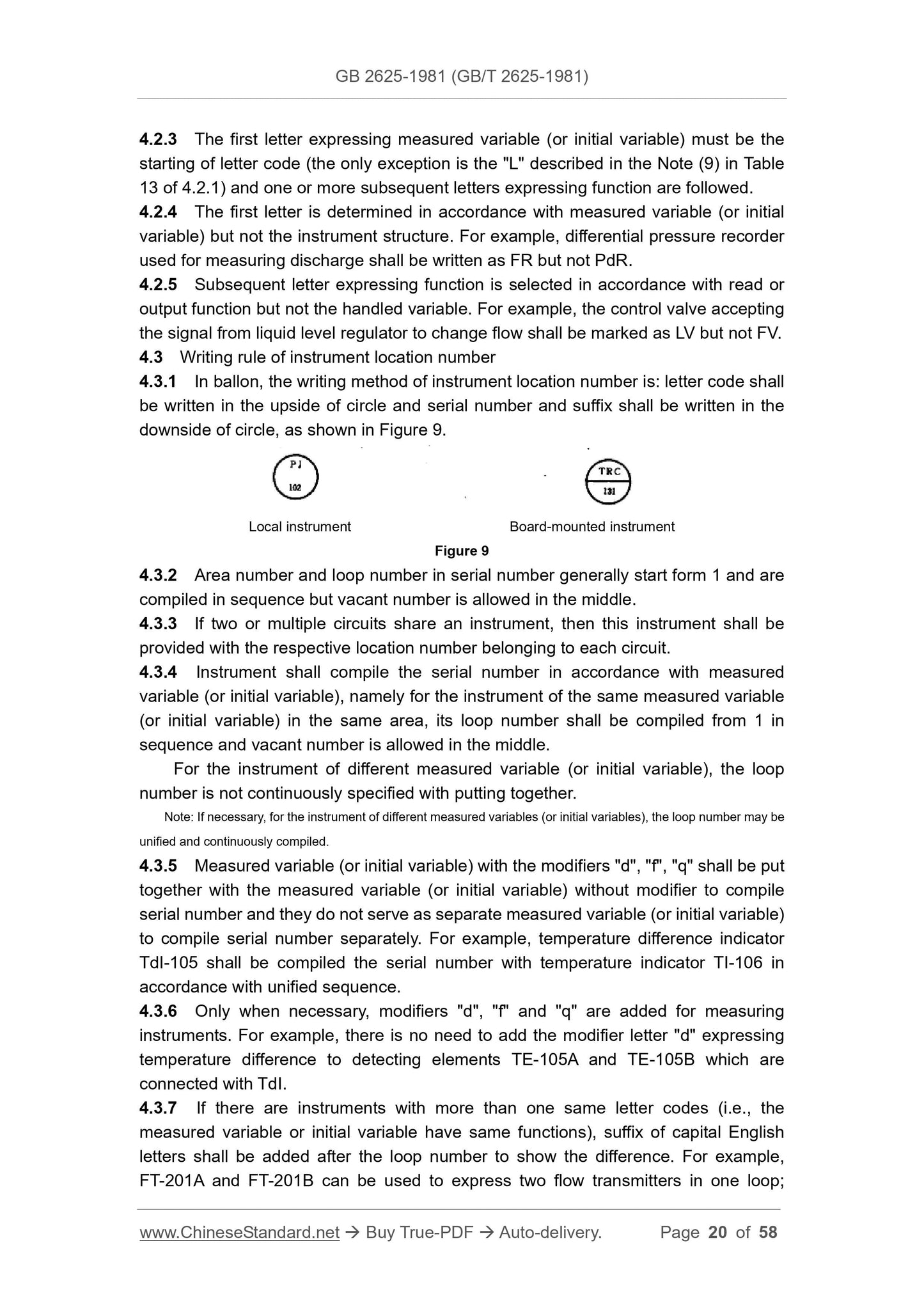
Process detection and controlflow chart. Symbols and letter codes
GB 2625-1981
NATIONAL STANDARD OF THE
PEOPLE’S REPUBLIC OF CHINA
GB 2625-81
Process Detection and Control Flow Chart
Symbols and Letter Codes
ISSUED ON: APRIL 1, 1981
IMPLEMENTED ON: MARCH 1, 1982
Issued by: National Bureau of Standards
Table of Contents
1. Introduction ... 4
2. Definitions ... 4
3. Symbols ... 6
4 Letter Codes ... 16
Appendix 1 ... 25
Appendix 2 ... 56
Process Detection and Control Flow Chart
Symbols and Letter Codes
1. Introduction
1.1 This standard is applicable to chemical industry, petroleum industry,
metallurgical industry, electricity industry, light industry, textile industry, building
materials industry and other industries. It aims at specifying unified representation
method for the instrument devices used in process detection and control flow chart.
The symbols and letter codes specified in this standard may also be used in other
design and technical documents.
1.2 The mark of instrument device is composed of symbols and letter codes.
1.3 All departments may put forward supplementary provisions under the condition
that requirements of this standard are not violated.
2. Definitions
For the purposes of this standard, the following definitions apply.
2.1 Process
It refers to any operation or a series of operations that can change energy status,
composition, dimension or other characteristics defined by the data available.
2.2 Function
It refers to the purpose and actions achieved by instruments.
2.3 Loop
It refers to the combination of one or more relevant instruments used for
measuring and (or) controlling process variables.
2.4 Ballon
It refers to the circular symbol used to indicate instrument or instrument mark.
2.5 Point of measurement
It refers to the point at which process variable may be measured.
2.6 Test point
It refers to the test joint to which instruments are not permanently connected and
it is used for connecting instruments temporarily, intermittently or in future.
2.7 Detecting element, sensor, primary element
It refers to the element responding to the value of measured variable directly and
converting measured variable to the form suitable for measurement.
2.8 Transmitter
It refers to the instrument which receives measured variable with the help of
detecting element and coverts the measured variable to standard output signal.
Transmitter may or may not include detecting elements.
2.9 Relay
It refers to the instrument which receives the information of one or more
instrument in signal form and may change information and output one or more output
signal(s) if required. It is the generic term of converter, computing instrument, signal
selector and amplifier, etc., but does not include switch and controller, etc.
2.10 Computing instrument
It refers to the instrument which completes one or more calculation and (or) logic
function and outputs one or more signals.
2.11 Signal converter
It refers to the instrument which receives the information of instrument in signal
form, changes information form and outputs one signal.
2.12 Signal selector
It refers to the instrument which selects the maximum or minimum input signal
automatically from two or more input signals.
2.13 Alarm
It refers to the sound and (or) light signal sent out when there is abnormal state in
order to attract attention.
The instrument with the above-mentioned function is referred to as alarm
apparatus.
2.14 Scan
It refers to the automatic sampling from several input signals orderly.
2.15 Pilot light
It refers to the light indicating that process or equipment keeps at certain normal
state. It is different form the alarm light which indicates an abnormal state.
Note: Pilot light may be accompanied by audible signal.
2.16 Switch
It refers to the device connecting, disconnecting or converting one or more lines
(not controller, relay or control valve).
This terminology is also applicable to the function completed by switch.
2.17 Controller
It refers to the instrument operating automatically to control certain controlled
variable.
2.18 Control station
It refers to the instrument which is able to select the manual or automatic control
mode for controlling loop manually.
2.19 Manual loading station
It refers to the instrument which only has manual adjustment output and is used
for operating one or more remote equipment.
2.20 Set point
It refers to the input variable used for setting the expected value of controlled
variable. The value of input variable may be set manually, automatically or by
procedure.
2.21 Final control element; correcting unit,
It refers to the instrument responding to signal so as to change value of
manipulated variable. It is composed of actuating element and correcting element.
2.22 Control valve
It refers to the actuator responding to signal so as to change fluid flow.
2.23 Actuator, actuating element
It refers to a part of final control element and is used to respond to the signal of
controller and the like so as to adjust correcting element.
2.24 Correcting element
It refers to a part of final control element and is used to change value of
manipulated variable directly.
2.25 Board
It refers to the structural part composed of one or several screen(s), cabinet(s),
platform(s) or frame(s) used to install instruments.
2.26 Board-mounted
It refers to that instrument is installed on the board that operation personnel can
approach during normal use.
2.27 Mounted behind the board
It refers to that instrument is installed in the instrument board area that operation
personnel cannot approach during normal use.
Note: Mounted behind the board includes board-mounted.
2.28 Local
It refers to the position of instrument neither on the board nor behind the board;
generally, it refers to the position near the point of measurement or steering point.
2.29 Local board
Generally, it refers to the instrument board near subsystem or partition of process
equipment.
2.30 Multiple-pen recorder (multiple-pointer indicator)
It refers to the recorder (indicator) suitable for multiple input signals, each input
signal is provided with separate recording pen (pointer) or other recording device
(indicating device).
2.31 Multiple-channel recorder (indicator)
It refers to the recorder (indicator) suitable for multiple input signals; different
input signals are connected to the measurement line of recorder (indicator) orderly, so
the recorder (indicator) records (indicates) the value of input signal in sequence.
3. Symbols
3.1 Point of measurement
3.1.1 Points of measurement are the starting points of lines leading to ballon via the
equipment outline or pipeline. Generally, there is no specific symbol, as shown in
Figure 1.
○3 The significance expressed by the subsequent letters may be noun, verb or adjective. For example, "1"
may be indicator, indication or indicated and "T" may be transmitter, transmission or transmitting.
○4 One of the modifier letters of the first letter "d" (difference),"f" (ratio) , "q" (integral, accumulation)
constitutes another significance of measured variable by combining with the letter of measured variable (or
initial variable), thus it shall be considered as one letter. For example: TdI and TI respectively are
temperature difference indication and temperature indication.
Modification letter shall be lowercase. It may also be capital when there is no c...
View full details