1
/
of
9
PayPal, credit cards. Download editable-PDF and invoice in 1 second!
GB/T 25984.1-2010 English PDF (GBT25984.1-2010)
Regular price
$145.00 USD
Regular price
Sale price
$145.00 USD
Unit price
/
per
Shipping calculated at checkout.
Couldn't load pickup availability
Delivery: 3 seconds. Download true-PDF + Invoice.
Get Quotation: Click GB/T 25984.1-2010 (Self-service in 1-minute)
Historical versions (Master-website): GB/T 25984.1-2010
Preview True-PDF (Reload/Scroll-down if blank)
GB/T 25984.1-2010: Automobiles Electric Fuel Pump - Part 1: Brush Electric Fuel Pump
GB/T 25984.1-2010
Automobiles electric fuel pump.Part 1. Brushelectric fuel pump
ICS 43.040.10
T36
National Standards of People's Republic of China
Automotive electric fuel pump
Part 1. Brushed electric fuel pump
Part 1. Brush'selectricfuelpump
Published on.2011-01-10
2011-05-01 implementation
General Administration of Quality Supervision, Inspection and Quarantine of the People's Republic of China
China National Standardization Administration issued
Foreword
GB/T 25984 "Automotive electric fuel pump" consists of two parts.
--- Part 1. Brushed electric fuel pump;
--- Part 2. Brushless electric fuel pump.
This part is the first part of GB/T 25984.
This part is proposed by the National Development and Reform Commission of the People's Republic of China.
This part is under the jurisdiction of the National Automotive Standardization Technical Committee (SAC/TC114).
This section drafted by. Wenzhou China Resources Motor Co., Ltd., Changsha Automobile Electric Apparatus Research Institute, Huirun Electromechanical Co., Ltd.
Drafters of this section. Xue Yujiang, Shu Guangyuan, Hu Mengyu, Li Weiyang.
Automotive electric fuel pump
Part 1. Brushed electric fuel pump
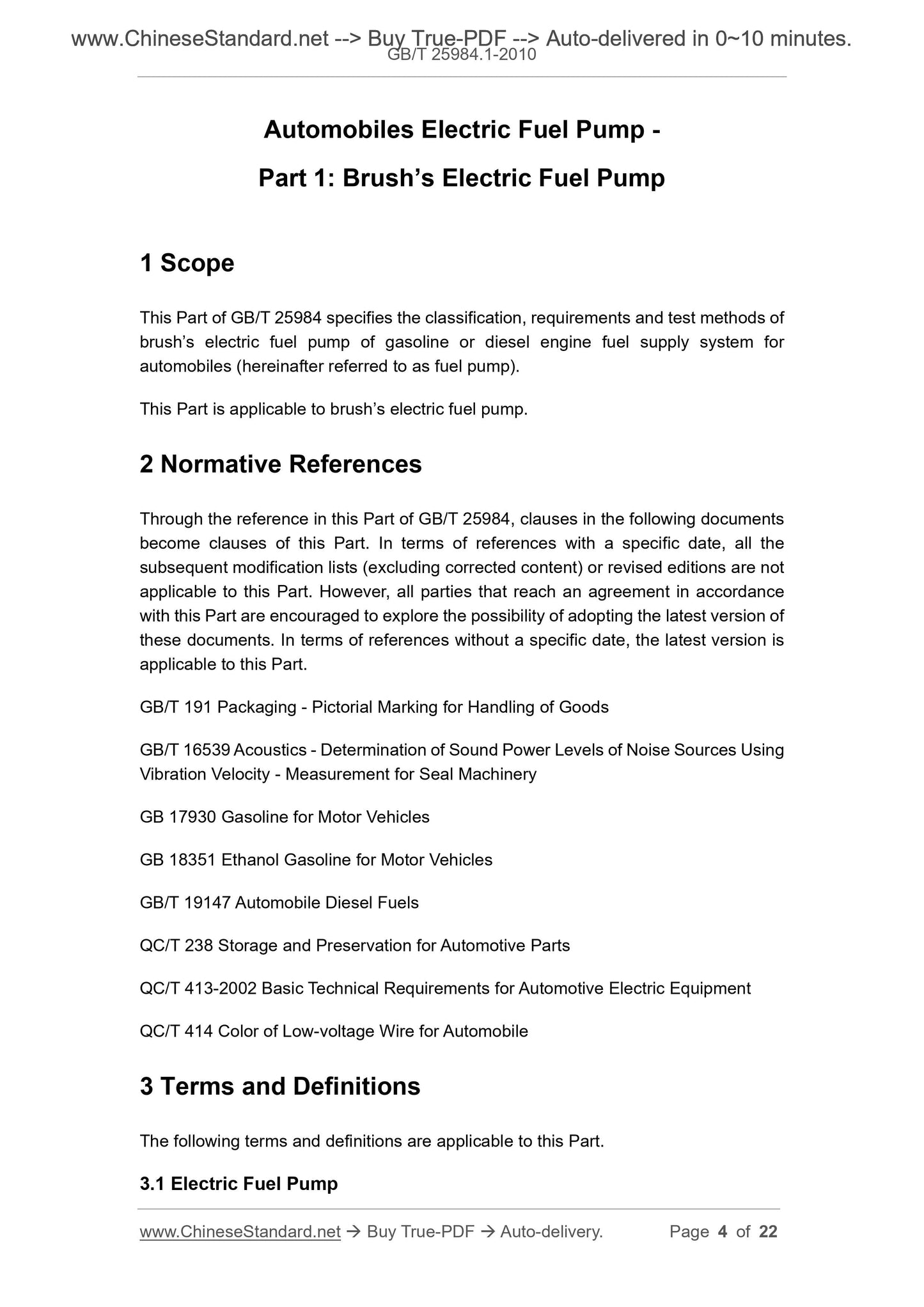
1 Scope
This part of GB/T 25984 specifies a brushed electric fuel pump for gasoline or diesel engine fuel supply systems for automobiles (hereinafter referred to as.
Classification, requirements, test methods, etc. of oil pumps).
This section applies to brushed electric fuel pumps.
2 Normative references
The terms in the following documents become the provisions of this part by reference to this part of GB/T 25984. For dated references,
All subsequent amendments (not including errata content) or revisions do not apply to this section, however, an agreement is reached under this section.
The parties studied whether the latest version of these documents could be used. For undated references, the latest edition applies to this section.
GB/T 191 packaging storage and transportation icon
GB/T 16539 Acoustic vibration velocity method for the determination of noise source power level for the measurement of closed machines
GB 17930 motor gasoline
GB 18351 car ethanol gasoline
GB/T 19147 vehicle diesel
QC/T 238 Storage and storage of auto parts
QC/T 413-2002 Basic technical conditions for automotive electrical equipment
QC/T 414 color of low voltage wires for automobiles
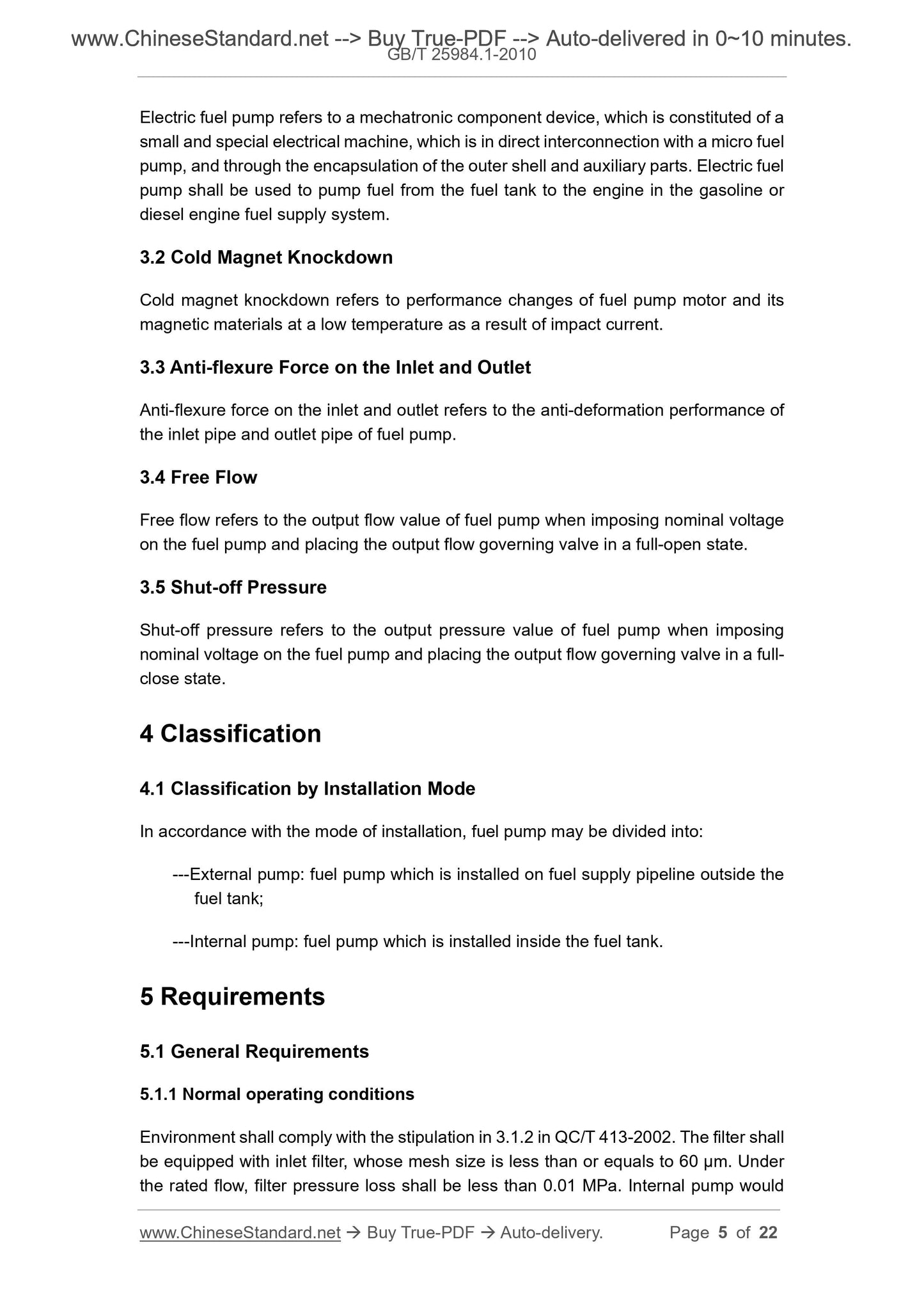
3 Terms and definitions
The following terms and definitions apply to this section.
3.1
Electric fuel pump electricfuelpump
A micro-oil pump directly connected to the micro-motor, and a mechatronic component device consisting of a casing and an auxiliary component package. Used for
The fuel in the fuel tank is delivered to the engine in a gasoline or diesel engine fuel supply system.
3.2
Cold magnetic shock performance coldmagnetknockdown
Performance changes of the fuel pump motor and its magnetic material due to inrush current at low temperatures.
3.3
Anti-flexureforceontheinletandoutlet
Fuel pump inlet or outlet pipe anti-deformation performance.
3.4
Free flow freeflow
Apply a nominal voltage to the fuel pump and place the output flow regulator valve at the fuel pump output flow value at full opening.
3.5
Shutoff pressure shutoffpressure
Applying a nominal voltage to the fuel pump will output the fuel pump output pressure when the flow regulator is fully closed.
4 classification
4.1 Classification by installation method
The fuel pump can be divided into.
---External pump. a fuel pump installed on the oil supply pipe outside the fuel tank;
--- Built-in pump. The fuel pump installed in the fuel tank.
5 requirements
5.1 General requirements
5.1.1 Normal working conditions
The environment is as specified in 3.1.2 of QC/T 413-2002. The filter should be equipped with a filter into the oil port. The mesh is less than or equal to 60μm.
The filter pressure loss at a constant flow rate is less than 0.01 MPa. The built-in pump product has an axial length of 1/2 or more and is partially immersed in the oil to work. External pump
There is oil in it to work.
Unless otherwise specified, the test is performed perpendicular to the horizontal plane of the motor shaft.
5.1.2 Temperature range
The working temperature is -30 ° C ~ 65 ° C; the storage temperature is -40 ° C ~ 75 ° C.
5.1.3 Working voltage
The fuel pump shall be capable of starting the engine at the minimum and maximum voltages in Table 1.
Table 1 Working voltage
Operating Voltage
Minimum Maximum
5.1.4 Direction of oil transportation
In addition to the obvious discrimination, the fuel pump should have a mark indicating the flow direction of the incoming and outgoing oil.
5.1.5 Working system
The working characteristics of the fuel pump are continuous quota system.
5.1.6 Appearance, installation dimensions and signs
The fuel pump shall be free from obvious damage, cracks, shrinkage, deformation, corrosion and other defects that hinder the operation and performance of the fuel pump.
Less than 10g of residual oil. Installation dimensions and markings shall be in accordance with the product technical documentation.
5.1.7 Mechanical fastener tightening torque
It should be specified in the product technical documentation.
5.1.8 Low voltage wiring harness
The low voltage wiring harness used in the fuel pump shall comply with the provisions of 3.2.3 of QC/T 413-2002.
5.1.9 Anti-flexibility force of inlet and outlet interface
The deflection resistance of the inlet and outlet interface parts shall comply with the provisions of the product technical documents.
5.2 Performance
5.2.1 Main performance parameters
Rated current, rated pressure, rated flow, free flow and shut-off pressure shall be in accordance with the product technical documents.
5.2.2 Check valve performance
5.2.2.1 Check valve leakage
The leakage of the test fluid should be less than 3mL/h under the pressure of 0.23MPa.
5.2.2.2 Check valve life
After the check valve is opened and closed for 100,000 times, the performance of the check valve shall comply with the provisions of 5.2.2.1.
5.2.3 Pressure relief valve operating range
If the rated pressure value is pn, the lower limit of the pressure relief valve opening is pn 0.1MPa, and the upper limit of the full opening of the pressure relief valve is pn 0.5MPa;
If the rated pressure value pn is less than 0.1 MPa, the upper limit of the full opening of the pressure relief valve is pn 0.2 MPa. The shutoff value of the pressure relief valve should be greater than pn.
5.3 Noise
The fuel pump noise should be less than 70dB (A).
5.4 Resistance to abnormal power supply voltage performance
5.4.1 Resistance to power polarity reverse connection performance
The fuel pump should be able to withstand a 1 minute power polarity reverse connection test without damage, and the reverse voltage value is 7/6 times the nominal voltage. After the test,
The product shall comply with the provisions of 5.2.1.
5.4.2 Resistance to overvoltage performance
The fuel pump shall be capable of withstanding the power supply overvoltage test of 10 min and 1.5 times the nominal voltage. After the test, the product shall comply with the provisions of 5.2.1.
5.5 Withstand voltage (pmax)
The external pump should have no leakage and deformation damage under pmax; the built-in pump allows leakage without affecting performance, but deformation and damage are not allowed.
Pmax is as follows.
--- If the rated pressure pn is (0.1~0.6) MPa, pmax should be not less than pn 0.5MPa;
--- If the rated pressure pn is less than 0.1MPa, pmax should be no less than pn 0.3MPa.
5.6 Cold magnetic shock performance
After the fuel pump is restored to the normal temperature state by the cold magnetic shock test, the current increase of the fuel pump should not exceed the current value at the nominal voltage.
10%.
5.7 Low temperature and low voltage performance
At -30 ° C, load 75% of the nominal voltage, after running for 15 s at 80% of the rated pressure, the fuel pump flow should be greater than the rated flow
10%.
5.8 Explosion-proof performance
The fuel pump cannot ignite a flammable air/fuel mixture.
5.9 Electromagnetic disturbance
The electromagnetic disturbance of the fuel pump is determined by both the supplier and the buyer.
5.10 Temperature resistance
5.10.1 Low temperature storage resistance
The fuel pump is tested at -40 ° C for 8 h at low temperature. After the product returns to normal temperature, its performance should meet the requirements of 5.2.1.
5.10.2 High temperature resistance
5.10.2.1 High temperature storage performance
The fuel pump is tested at 75 ° C for 8 h. After the product returns to normal temperature, its performance should meet the requirements of 5.2.1.
5.10.2.2 High temperature work performance
When the oil temperature rises from room temperature to the maximum working temperature value, it runs for 60 minutes at the nominal voltage and rated pressure, and the fuel pump flow rate should be
The rated value is above 75%. After the product returns to normal temperature, its performance should meet the requirements of 5.2.1.
5.10.3 Resistance to temperature change performance
The fuel pump shall be tested for temperature change in accordance with 3.10.3 of QC/T 413-2002, and the product shall be tested under non-operating conditions.
The low temperature and high temperature values during the test were selected from -30 ° C to 65 ° C, and the exposure time at each temperature was selected to be 2 h. After the test, the product
Return to normal temperature, should comply with the provisions of 5.2.1.
5.11 Resistance to temperature/humidity cycle change performance (for external pump)
The external pump shall be subjected to the test in the non-operating state between -10 ° C and 65 ° C according to the provisions of 3.11 of QC/T 413-2002.
After the test is over and the product returns to normal temperature, the product shall comply with the provisions of 5.1.9 and 5.2.1.
5.12 Vibration resistance
The fuel pump is subjected to the test under normal working conditions of non-operation. The severity of the sweeping vibration test shall be in accordance with QC/T 413-2002.
Table 3 "Other parts", the frequency range is selected as (25 ~ 500) Hz. After the vibration test, the product should be free from damage and the fasteners should be loose.
Image should comply with the provisions of 5.2.1.
5.13 Salt spray resistance
The fuel pump should be tested for salt spray resistance. The test time of the external pump is 144h, and the test time of the built-in pump is 48h.
Corrosion of 5% of the outer surface area of the metal.
5.14 Fuel resistance
The fuel pump adopts three kinds of oils corresponding to the engine, and is subjected to the whole product immersion test under the non-operating state, and is immersed at normal temperature (internal
Fully filled) for 30 days. After the test, the product shall be retested in the oil required by the technical documentation and in accordance with the technical documents.
5.15 Surface protection properties
Unless otherwise specified, the surface protection properties of the product shall comply with the provisions of 3.15 of QC/T 413-2002.
5.16 Durability
After the fuel pump is subjected to the 3000h durability test at the nominal voltage and rated pressure, the product shall comply with the provisions of 5.2.1 (but the current is allowed
Within 10% increase, the flow rate is allowed to drop by less than 15%).
6 Test methods
6.1 Test conditions
6.1.1 Normal working conditions of the test
Unless otherwise specified, product testing shall be carried out under the normal operating conditions specified in 5.1.1. Before the test, the fuel pump should pass 30min
The above running-in performance is stable. The specific running-in time and method should be marked in the technical documents.
6.1.2 Temperature deviation
±2 °C should be used when there is no specific temperature deviation in the test.
6.1.3 Test power supply
The test power supply voltage can be adjusted in the range of (5~20)V when not specified, and the relative error of ±10% is allowed;
The 24V electrical system is (10~40)V, which allows a relative error of ±10%. The output power of the power supply is greater than or equal to 5 times the fuel pump input work
rate. The DC power supply for testing uses a car battery or a DC adjustable power supply with a ripple factor of no more than 0.1%.
6.1.4 Test instrument
The voltmeter and ammeter used in the test shall be not less than 0.5, the pressure gauge shall not be less than 1.5, and the flowmeter shall not be less than ±2%, allowing
Use a digital meter equivalent to the above accuracy.
6.1.5 Test solution
A liquid equivalent to the main physical properties (density, viscosity) of the fuel corresponding to the engine is used. This section recommends the use of the D60 special
Kerosene-based solvent oils, which ensure safety-tested conditions, allow gasoline to be used, not less than 10L/pump.
6.1.6 Pipeline
It is recommended to use metal pipes with an inner diameter of not less than 8mm and a wall thickness of not less than 1mm, without the use of non-reinforced rubber and plastic.
Tube, try to shorten the length and reduce the bending.
6.2 General requirements test
6.2.1 Shape test
The shape of the product is tested with a universal or special measuring tool, and the appearance and marking are checked by visual inspection.
6.2.2 Tightening torque test
The tightening torque of the mechanical fastener is measured with a torque wrench.
6.2.3 Low voltage wiring harness test
The performance test method for low-voltage wiring harness shall be carried out in accordance with 4.2.3 of QC/T 413-2002.
6.2.4 Anti-flexibility test of inlet and outlet interface
According to the device of Figure 1, take the root end of the oil pipe as the fulcrum, and apply force at 5mm from the oil outlet port as required. It takes 2min, and the oil pipe should not be used.
fracture.
6.2.5 Working voltage test
Under normal operating conditions, the fuel pump shall be carried out on the engine bench test equipment to meet the requirements of 5.1.3.
6.3 Performance tes...
Share