1
/
of
7
www.ChineseStandard.us -- Field Test Asia Pte. Ltd.
GB/T 25930-2010 English PDF (GB/T25930-2010)
Regular price
$190.00
Regular price
Sale price
$190.00
Unit price
/
per
Shipping calculated at checkout.
Couldn't load pickup availability
GB/T 25930-2010: Test method of infrared gas analyzers
Delivery: 9 seconds. Download (& Email) true-PDF + Invoice.
Get Quotation: Click GB/T 25930-2010 (Self-service in 1-minute)
Historical versions (Master-website): GB/T 25930-2010
Preview True-PDF (Reload/Scroll-down if blank)
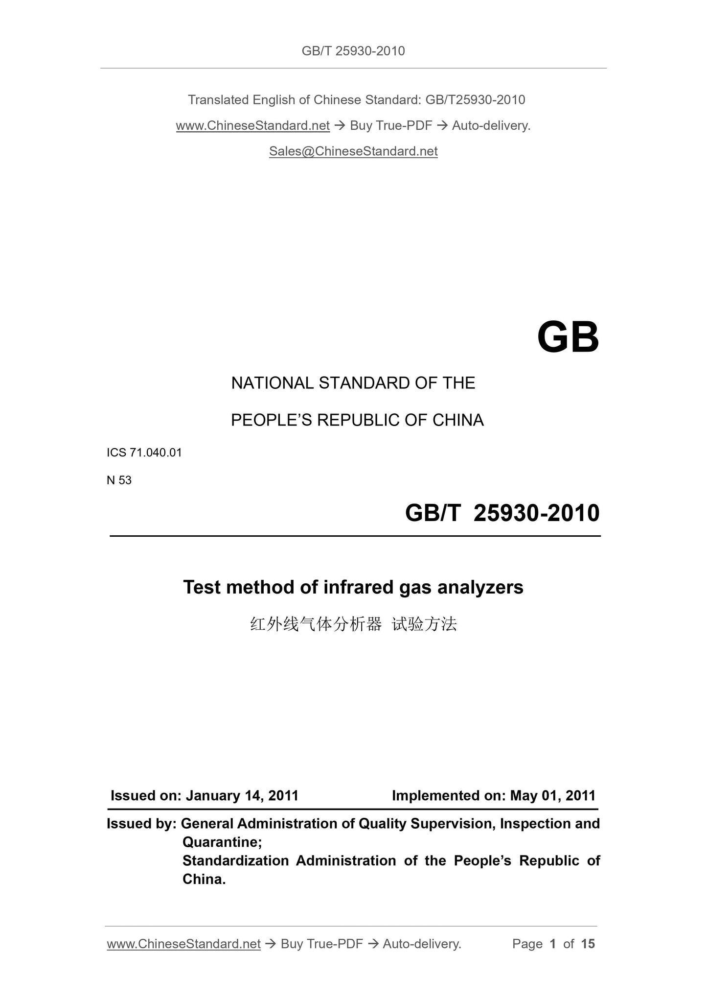
GB/T 25930-2010
GB
NATIONAL STANDARD OF THE
PEOPLE’S REPUBLIC OF CHINA
ICS 71.040.01
N 53
Test method of infrared gas analyzers
ISSUED ON: JANUARY 14, 2011
IMPLEMENTED ON: MAY 01, 2011
Issued by: General Administration of Quality Supervision, Inspection and
Quarantine;
Standardization Administration of the People’s Republic of
China.
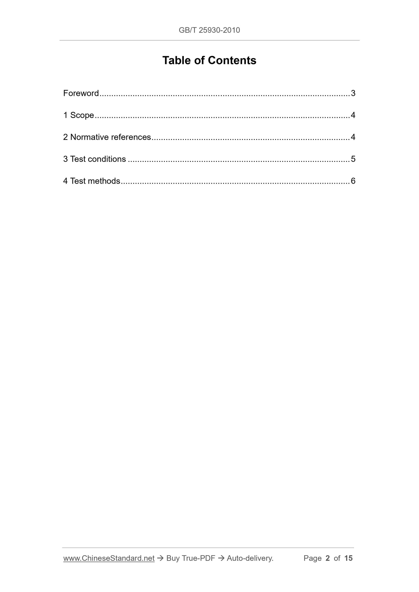
Table of Contents
Foreword ... 3
1 Scope ... 4
2 Normative references ... 4
3 Test conditions ... 5
4 Test methods ... 6
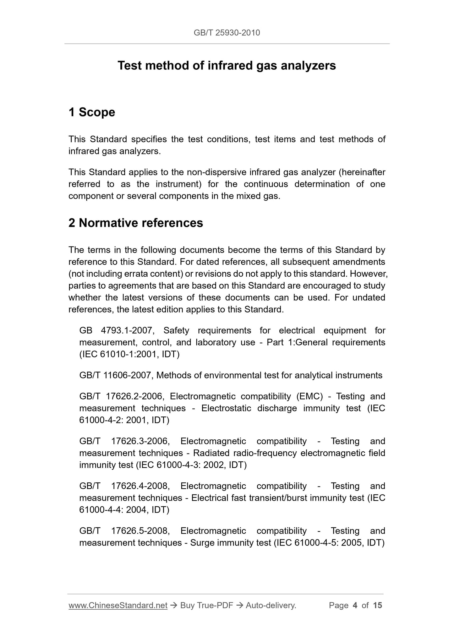
Test method of infrared gas analyzers
1 Scope
This Standard specifies the test conditions, test items and test methods of
infrared gas analyzers.
This Standard applies to the non-dispersive infrared gas analyzer (hereinafter
referred to as the instrument) for the continuous determination of one
component or several components in the mixed gas.
2 Normative references
The terms in the following documents become the terms of this Standard by
reference to this Standard. For dated references, all subsequent amendments
(not including errata content) or revisions do not apply to this standard. However,
parties to agreements that are based on this Standard are encouraged to study
whether the latest versions of these documents can be used. For undated
references, the latest edition applies to this Standard.
GB 4793.1-2007, Safety requirements for electrical equipment for
measurement, control, and laboratory use - Part 1:General requirements
(IEC 61010-1:2001, IDT)
GB/T 11606-2007, Methods of environmental test for analytical instruments
GB/T 17626.2-2006, Electromagnetic compatibility (EMC) - Testing and
measurement techniques - Electrostatic discharge immunity test (IEC
61000-4-2: 2001, IDT)
GB/T 17626.3-2006, Electromagnetic compatibility - Testing and
measurement techniques - Radiated radio-frequency electromagnetic field
immunity test (IEC 61000-4-3: 2002, IDT)
GB/T 17626.4-2008, Electromagnetic compatibility - Testing and
measurement techniques - Electrical fast transient/burst immunity test (IEC
61000-4-4: 2004, IDT)
GB/T 17626.5-2008, Electromagnetic compatibility - Testing and
measurement techniques - Surge immunity test (IEC 61000-4-5: 2005, IDT)
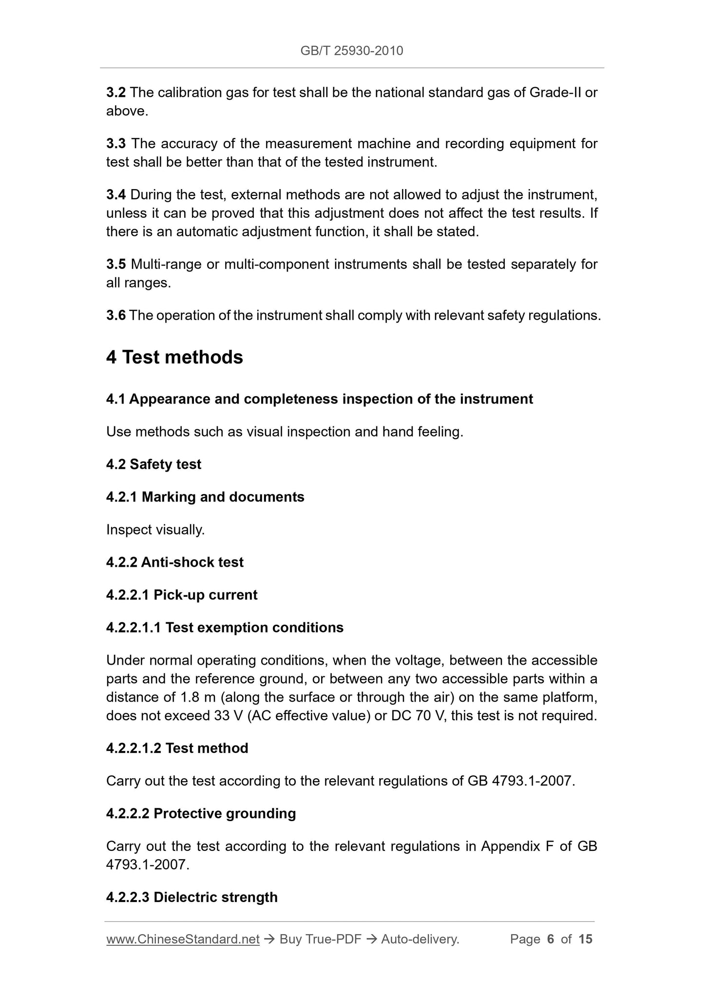
3.2 The calibration gas for test shall be the national standard gas of Grade-II or
above.
3.3 The accuracy of the measurement machine and recording equipment for
test shall be better than that of the tested instrument.
3.4 During the test, external methods are not allowed to adjust the instrument,
unless it can be proved that this adjustment does not affect the test results. If
there is an automatic adjustment function, it shall be stated.
3.5 Multi-range or multi-component instruments shall be tested separately for
all ranges.
3.6 The operation of the instrument shall comply with relevant safety regulations.
4 Test methods
4.1 Appearance and completeness inspection of the instrument
Use methods such as visual inspection and hand feeling.
4.2 Safety test
4.2.1 Marking and documents
Inspect visually.
4.2.2 Anti-shock test
4.2.2.1 Pick-up current
4.2.2.1.1 Test exemption conditions
Under normal operating conditions, when the voltage, between the accessible
parts and the reference ground, or between any two accessible parts within a
distance of 1.8 m (along the surface or through the air) on the same platform,
does not exceed 33 V (AC effective value) or DC 70 V, this test is not required.
4.2.2.1.2 Test method
Carry out the test according to the relevant regulations of GB 4793.1-2007.
4.2.2.2 Protective grounding
Carry out the test according to the relevant regulations in Appendix F of GB
4793.1-2007.
4.2.2.3 Dielectric strength
4.2.3 Other safety tests
Perform according to the method corresponding to GB 4793.1-2007.
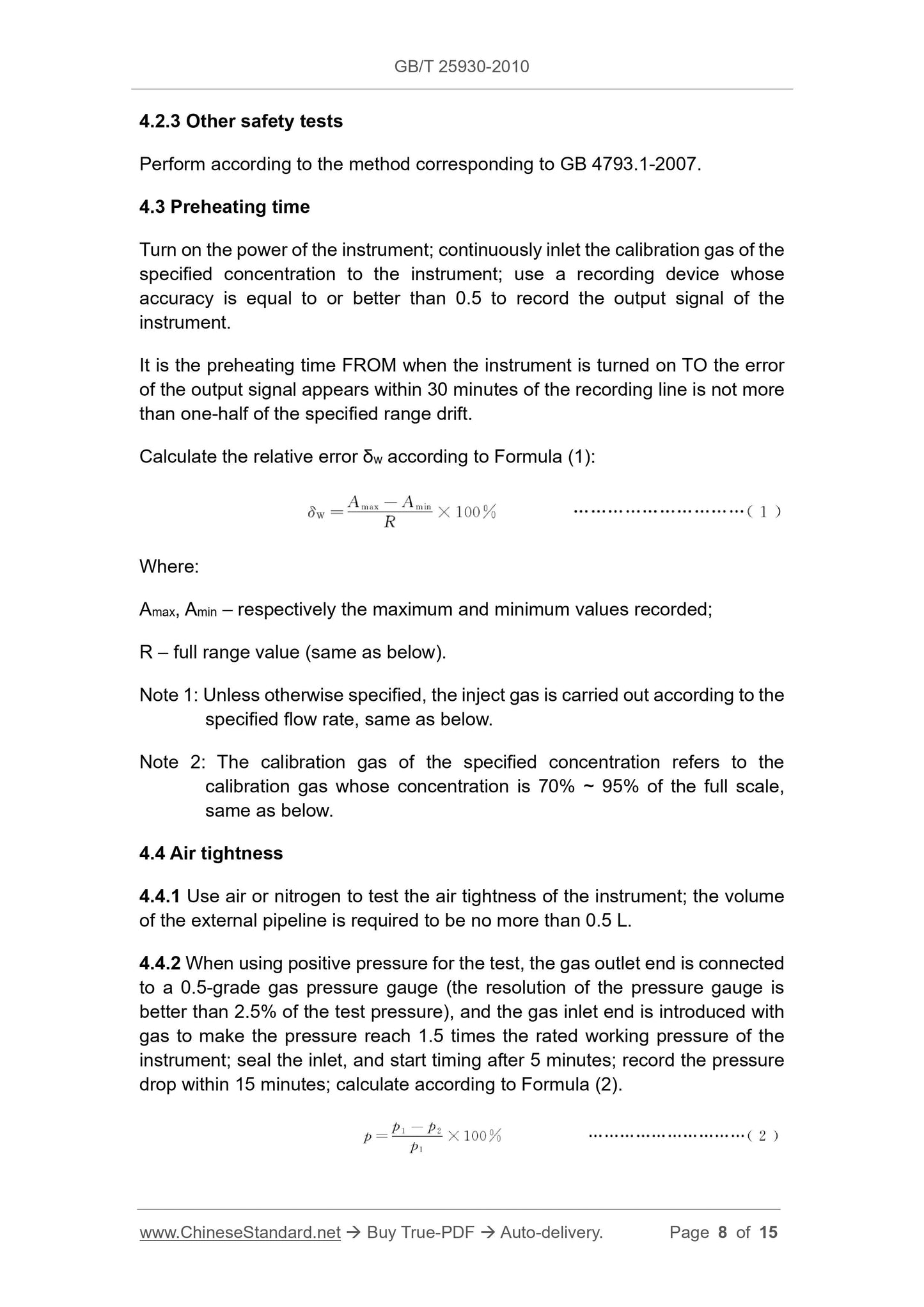
4.3 Preheating time
Turn on the power of the instrument; continuously inlet the calibration gas of the
specified concentration to the instrument; use a recording device whose
accuracy is equal to or better than 0.5 to record the output signal of the
instrument.
It is the preheating time FROM when the instrument is turned on TO the error
of the output signal appears within 30 minutes of the recording line is not more
than one-half of the specified range drift.
Calculate the relative error δw according to Formula (1):
Where:
Amax, Amin – respectively the maximum and minimum values recorded;
R – full range value (same as below).
Note 1: Unless otherwise specified, the inject gas is carried out according to the
specified flow rate, same as below.
Note 2: The calibration gas of the specified concentration refers to the
calibration gas whose concentration is 70% ~ 95% of the full scale,
same as below.
4.4 Air tightness
4.4.1 Use air or nitrogen to test the air tightness of the instrument; the volume
of the external pipeline is required to be no more than 0.5 L.
4.4.2 When using positive pressure for the test, the gas outlet end is connected
to a 0.5-grade gas pressure gauge (the resolution of the pressure gauge is
better than 2.5% of the test pressure), and the gas inlet end is introduced with
gas to make the pressure reach 1.5 times the rated working pressure of the
instrument; seal the inlet, and start timing after 5 minutes; record the pressure
drop within 15 minutes; calculate according to Formula (2).
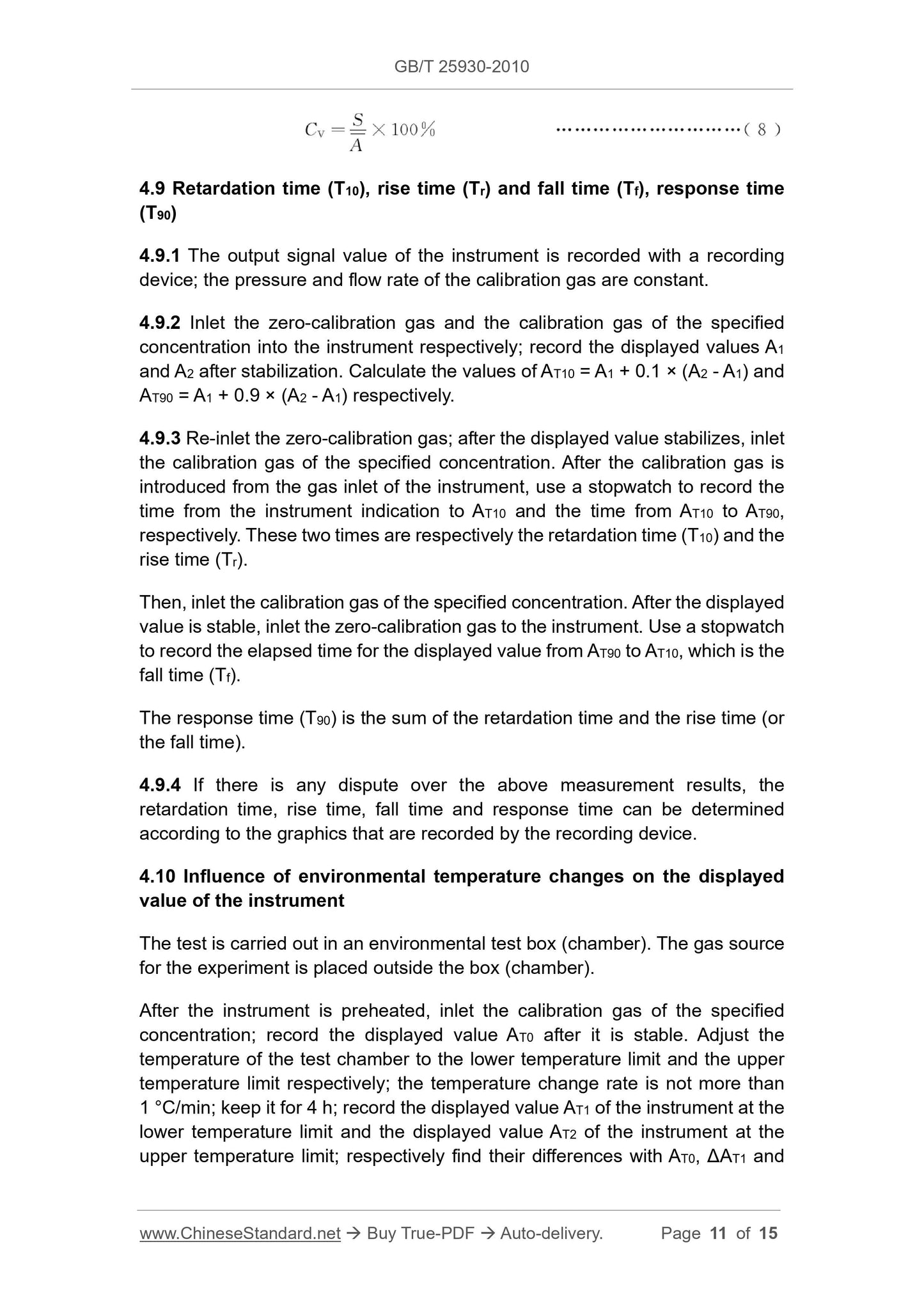
4.9 Retardation time (T10), rise time (Tr) and fall time (Tf), response time
(T90)
4.9.1 The output signal value of the instrument is recorded with a recording
device; the pressure and flow rate of the calibration gas are constant.
4.9.2 Inlet the zero-calibration gas and the calibration gas of the specified
concentration into the instrument respectively; record the displayed values A1
and A2 after stabilization. Calculate the values of AT10 = A1 + 0.1 × (A2 - A1) and
AT90 = A1 + 0.9 × (A2 - A1) respectively.
4.9.3 Re-inlet the zero-calibration gas; after the displayed value stabilizes, inlet
the calibration gas of the specified concentration. After the calibration gas is
introduced from the gas inlet of the instrument, use a stopwatch to record the
time from the instrument indication to AT10 and the time from AT10 to AT90,
respectively. These two times are respectively the retardation time (T10) and the
rise time (Tr).
Then, inlet the calibration gas of the specified concentration. After the displayed
value is stable, inlet the zero-calibration gas to the instrument. Use a stopwatch
to record the elapsed time for the displayed value from AT90 to AT10, which is the
fall time (Tf).
The response time (T90) is the sum of the retardation time and the rise time (or
the fall time).
4.9.4 If there is any dispute over the above measurement results, the
retardation time, rise time, fall time and response time can be determined
according to the graphics that are recorded by the recording device.
4.10 Influence of environmental temperature changes on the displayed
value of the instrument
The test is carried out in an environmental test box (chamber). The gas source
for the experiment is placed outside the box (chamber).
After the instrument is preheated, inlet the calibration gas of the specified
concentration; record the displayed value AT0 after it is stable. Adjust the
temperature of the test chamber to the lower temperature limit and the upper
temperature limit respectively; the temperature change rate is not more than
1 °C/min; keep it for 4 h; record the displayed value AT1 of the instrument at the
lower temperature limit and the displayed value AT2 of the instrument at the
upper temperature limit; respectively find their differences with AT0, ΔAT1 and
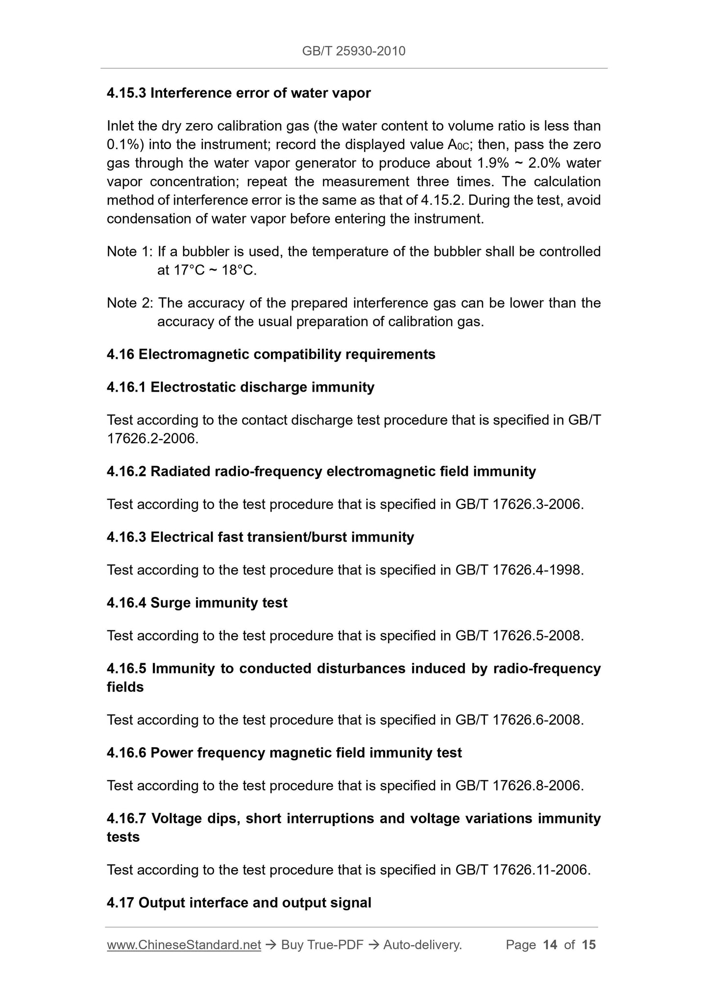
4.15.3 Interference error of water vapor
Inlet the dry zero calibration gas (the water content to volume ratio is less than
0.1%) into the instrument; record the displayed value A0C; then, pass the zero
gas through the water vapor generator to produce about 1.9% ~ 2.0% water
vapor concentration; repeat the measurement three times. The calculation
method of interference error is the same as that of 4.15.2. During the test, avoid
condensation of water vapor before entering the instrument.
Note 1: If a bubbler is used, the temperature of the bubbler shall be controlled
at 17°C ~ 18°C.
Note 2: The accuracy of the prepared interference gas can be lower than the
accuracy of the usual preparation of calibration gas.
4.16 Electromagnetic compatibility requirements
4.16.1 Electrostatic discharge immunity
Test according to the contact discharge test procedure that is specified in GB/T
17626.2-2006.
4.16.2 Radiated radio-frequency electromagnetic field immunity
Test according to the test procedure that is specified in GB/T 17626.3-2006.
4.16.3 Electrical fast transient/burst immunity
Test according to the test procedure that is specified in GB/T 17626.4-1998.
4.16.4 Surge immunity test
Test according to the test procedure that is specified in GB/T 17626.5-2008.
4.16.5 Immunity to conducted disturbances induced by radio-frequency
fields
Test according to the test procedure that is specified in GB/T 17626.6-2008.
4.16.6 Power frequency magnetic field immunity test
Test according to the test procedure that is specified in GB/T 17626.8-2006.
4.16.7 Voltage dips, short interruptions and voltage variations immunity
tests
Test according to the test procedure that is specified in GB/T 17626.11-2006.
4.17 Output interface and output signal
GB/T 25930-2010
GB
NATIONAL STANDARD OF THE
PEOPLE’S REPUBLIC OF CHINA
ICS 71.040.01
N 53
Test method of infrared gas analyzers
ISSUED ON: JANUARY 14, 2011
IMPLEMENTED ON: MAY 01, 2011
Issued by: General Administration of Quality Supervision, Inspection and
Quarantine;
Standardization Administration of the People’s Republic of
China.
Table of Contents
Foreword ... 3
1 Scope ... 4
2 Normative references ... 4
3 Test conditions ... 5
4 Test methods ... 6
Test method of infrared gas analyzers
1 Scope
This Standard specifies the test conditions, test items and test methods of
infrared gas analyzers.
This Standard applies to the non-dispersive infrared gas analyzer (hereinafter
referred to as the instrument) for the continuous determination of one
component or several components in the mixed gas.
2 Normative references
The terms in the following documents become the terms of this Standard by
reference to this Standard. For dated references, all subsequent amendments
(not including errata content) or revisions do not apply to this standard. However,
parties to agreements that are based on this Standard are encouraged to study
whether the latest versions of these documents can be used. For undated
references, the latest edition applies to this Standard.
GB 4793.1-2007, Safety requirements for electrical equipment for
measurement, control, and laboratory use - Part 1:General requirements
(IEC 61010-1:2001, IDT)
GB/T 11606-2007, Methods of environmental test for analytical instruments
GB/T 17626.2-2006, Electromagnetic compatibility (EMC) - Testing and
measurement techniques - Electrostatic discharge immunity test (IEC
61000-4-2: 2001, IDT)
GB/T 17626.3-2006, Electromagnetic compatibility - Testing and
measurement techniques - Radiated radio-frequency electromagnetic field
immunity test (IEC 61000-4-3: 2002, IDT)
GB/T 17626.4-2008, Electromagnetic compatibility - Testing and
measurement techniques - Electrical fast transient/burst immunity test (IEC
61000-4-4: 2004, IDT)
GB/T 17626.5-2008, Electromagnetic compatibility - Testing and
measurement techniques - Surge immunity test (IEC 61000-4-5: 2005, IDT)
3.2 The calibration gas for test shall be the national standard gas of Grade-II or
above.
3.3 The accuracy of the measurement machine and recording equipment for
test shall be better than that of the tested instrument.
3.4 During the test, external methods are not allowed to adjust the instrument,
unless it can be proved that this adjustment does not affect the test results. If
there is an automatic adjustment function, it shall be stated.
3.5 Multi-range or multi-component instruments shall be tested separately for
all ranges.
3.6 The operation of the instrument shall comply with relevant safety regulations.
4 Test methods
4.1 Appearance and completeness inspection of the instrument
Use methods such as visual inspection and hand feeling.
4.2 Safety test
4.2.1 Marking and documents
Inspect visually.
4.2.2 Anti-shock test
4.2.2.1 Pick-up current
4.2.2.1.1 Test exemption conditions
Under normal operating conditions, when the voltage, between the accessible
parts and the reference ground, or between any two accessible parts within a
distance of 1.8 m (along the surface or through the air) on the same platform,
does not exceed 33 V (AC effective value) or DC 70 V, this test is not required.
4.2.2.1.2 Test method
Carry out the test according to the relevant regulations of GB 4793.1-2007.
4.2.2.2 Protective grounding
Carry out the test according to the relevant regulations in Appendix F of GB
4793.1-2007.
4.2.2.3 Dielectric strength
4.2.3 Other safety tests
Perform according to the method corresponding to GB 4793.1-2007.
4.3 Preheating time
Turn on the power of the instrument; continuously inlet the calibration gas of the
specified concentration to the instrument; use a recording device whose
accuracy is equal to or better than 0.5 to record the output signal of the
instrument.
It is the preheating time FROM when the instrument is turned on TO the error
of the output signal appears within 30 minutes of the recording line is not more
than one-half of the specified range drift.
Calculate the relative error δw according to Formula (1):
Where:
Amax, Amin – respectively the maximum and minimum values recorded;
R – full range value (same as below).
Note 1: Unless otherwise specified, the inject gas is carried out according to the
specified flow rate, same as below.
Note 2: The calib...
Share