1
/
of
8
www.ChineseStandard.us -- Field Test Asia Pte. Ltd.
GB/T 25929-2010 English PDF (GB/T25929-2010)
GB/T 25929-2010 English PDF (GB/T25929-2010)
Regular price
$190.00
Regular price
Sale price
$190.00
Unit price
/
per
Shipping calculated at checkout.
Couldn't load pickup availability
GB/T 25929-2010: Specification of infrared gas analyzers
Delivery: 9 seconds. Download (and Email) true-PDF + Invoice.Get Quotation: Click GB/T 25929-2010 (Self-service in 1-minute)
Newer / historical versions: GB/T 25929-2010
Preview True-PDF
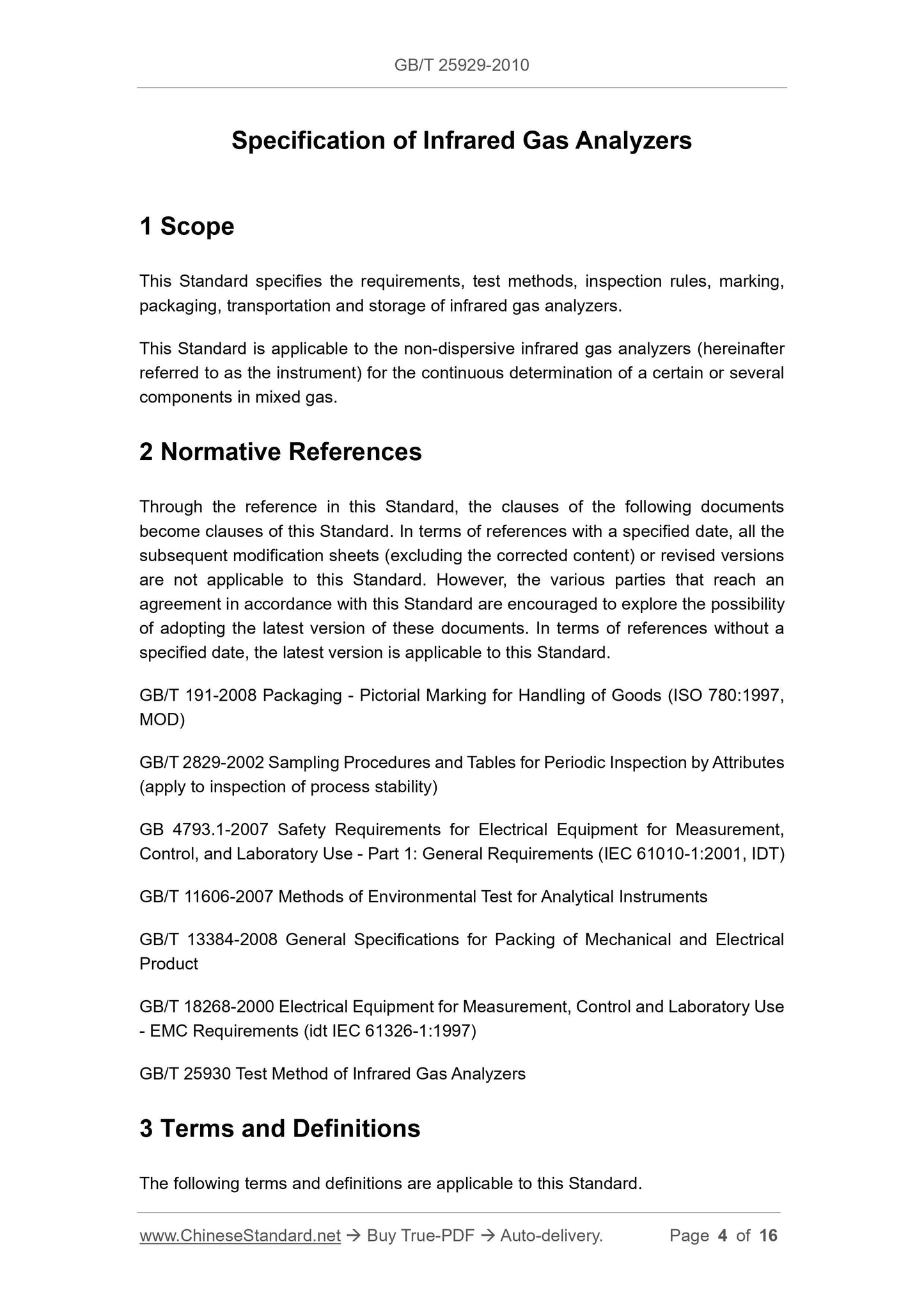
Scope
This Standard specifies the requirements, test methods, inspection rules, marking,packaging, transportation and storage of infrared gas analyzers.
This Standard is applicable to the non-dispersive infrared gas analyzers (hereinafter
referred to as the instrument) for the continuous determination of a certain or several
components in mixed gas.
Basic Data
| Standard ID | GB/T 25929-2010 (GB/T25929-2010) |
| Description (Translated English) | Specification of infrared gas analyzers |
| Sector / Industry | National Standard (Recommended) |
| Classification of Chinese Standard | N53 |
| Classification of International Standard | 71.040.01 |
| Word Count Estimation | 10,193 |
| Date of Issue | 1/14/2011 |
| Date of Implementation | 5/1/2011 |
| Quoted Standard | GB/T 191-2008; GB/T 2829-2002; GB 4793.1-2007; GB/T 11606-2007; GB/T 13384-2008; GB/T 18268-2000; GB/T 25930 |
| Regulation (derived from) | Announcement of Newly Approved National Standards No. 2 of 2011 |
| Issuing agency(ies) | General Administration of Quality Supervision, Inspection and Quarantine of the People's Republic of China, Standardization Administration of the People's Republic of China |
| Summary | This Standard specifies requirements for an infrared gas analyzer, test methods, inspection rules, marking, packaging, transportation and storage. This Standard is applicable to continuous determination of the components of a gas mixture of several components, regardless of light or infrared gas analyzer (hereinafter referred to as the instrument). |
Share