GB/T 25389.2-2018 English PDF (GBT25389.2-2018)
Regular price
$260.00 USD
Regular price
Sale price
$260.00 USD
Unit price
/
per
Delivery: 3 seconds. Download true-PDF + Invoice.
Get QUOTATION in 1-minute: Click GB/T 25389.2-2018
Historical versions: GB/T 25389.2-2018
Preview True-PDF (Reload/Scroll if blank)
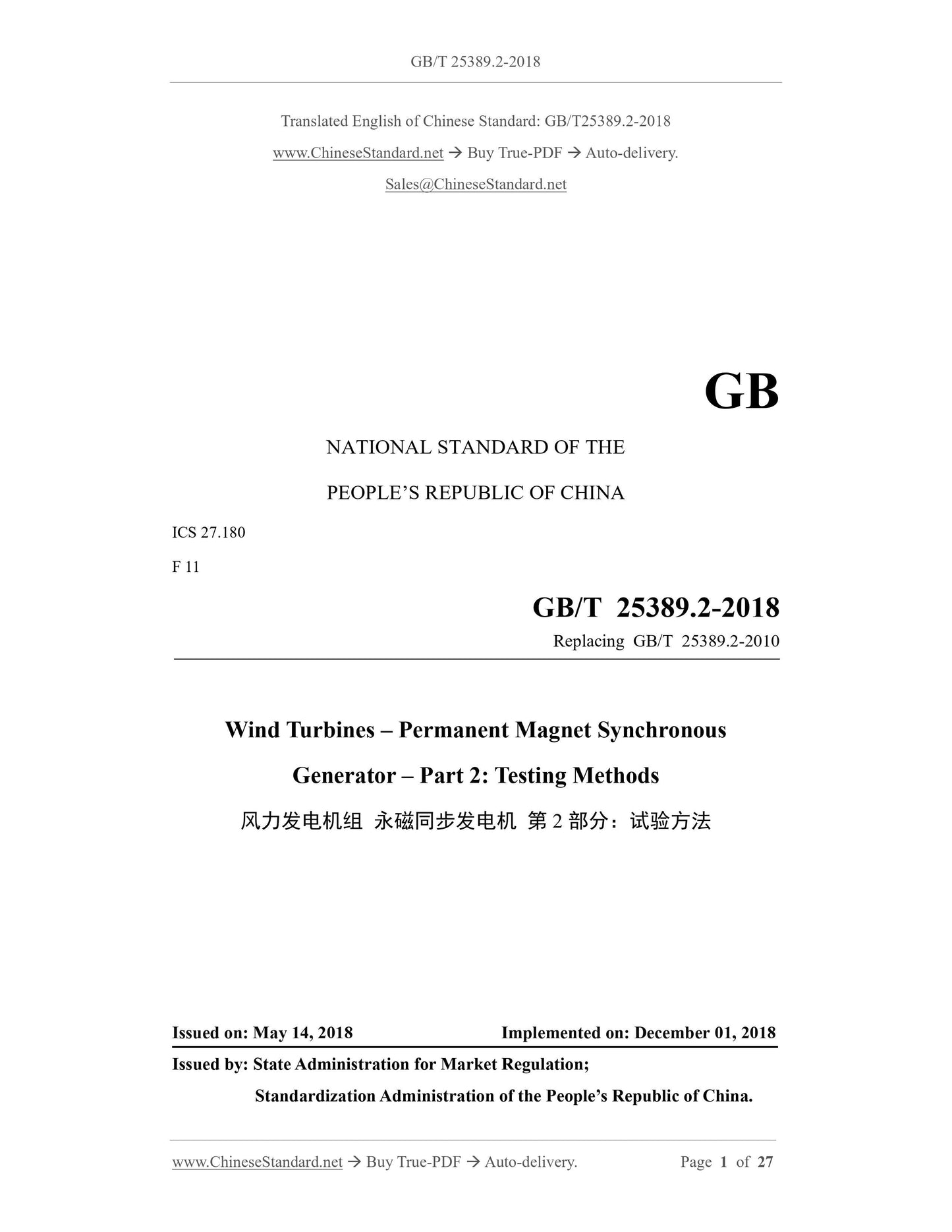
GB/T 25389.2-2018: Wind turbines -- Permanent magnet synchronous generator -- Part 2: Testing methods
GB/T 25389.2-2018
GB
NATIONAL STANDARD OF THE
PEOPLE’S REPUBLIC OF CHINA
ICS 27.180
F 11
Replacing GB/T 25389.2-2010
Wind Turbines – Permanent Magnet Synchronous
Generator – Part 2: Testing Methods
ISSUED ON: MAY 14, 2018
IMPLEMENTED ON: DECEMBER 01, 2018
Issued by: State Administration for Market Regulation;
Standardization Administration of the People’s Republic of China.
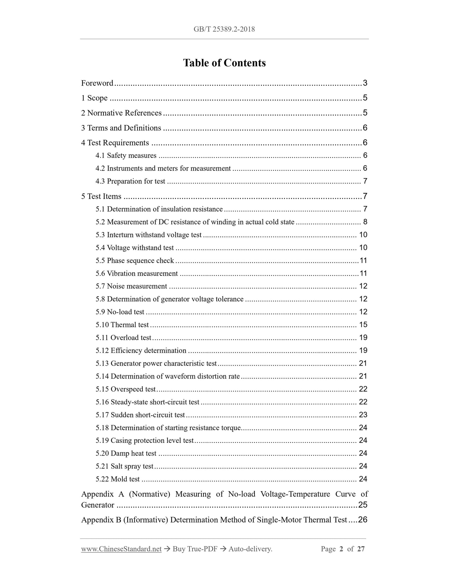
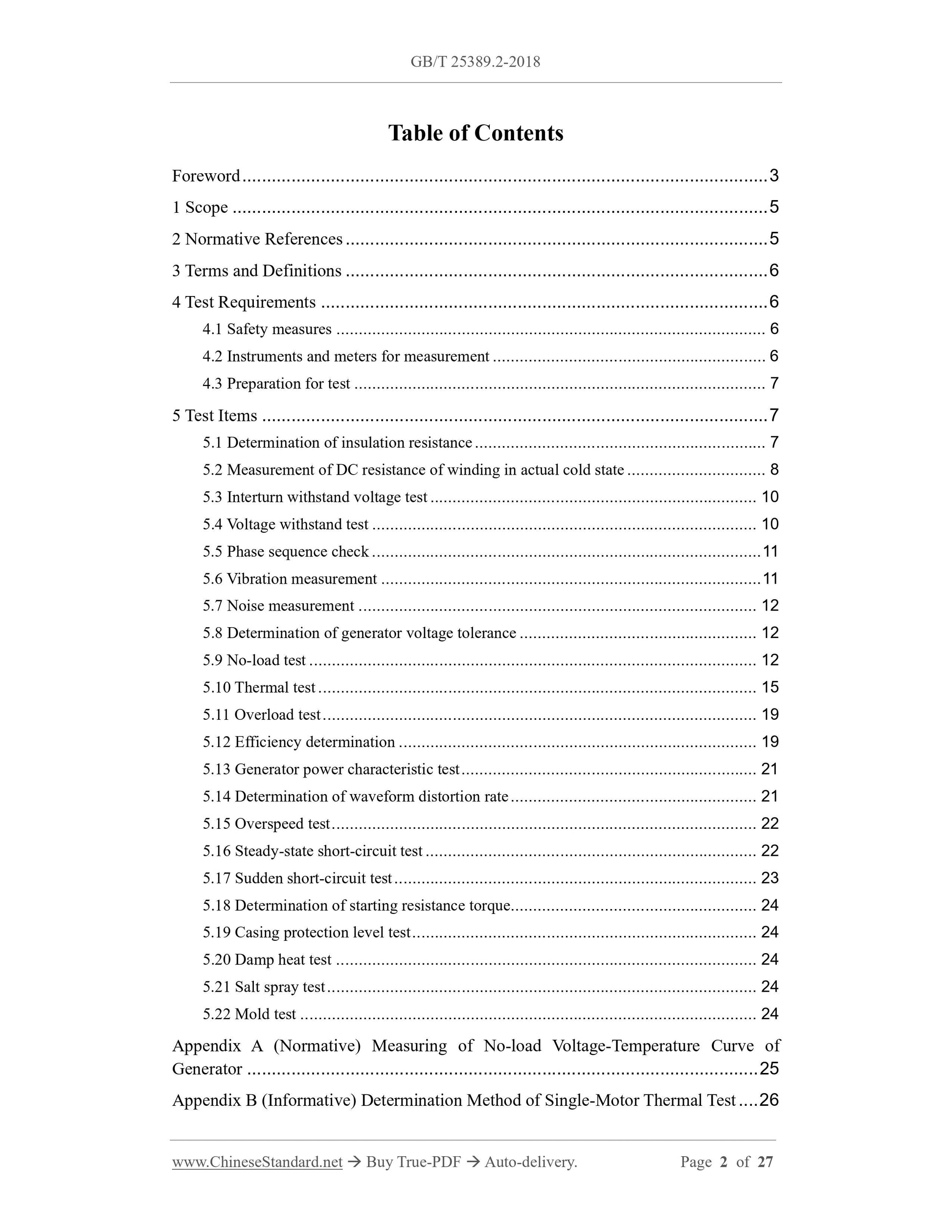
Table of Contents
Foreword ... 3
1 Scope ... 5
2 Normative References ... 5
3 Terms and Definitions ... 6
4 Test Requirements ... 6
4.1 Safety measures ... 6
4.2 Instruments and meters for measurement ... 6
4.3 Preparation for test ... 7
5 Test Items ... 7
5.1 Determination of insulation resistance ... 7
5.2 Measurement of DC resistance of winding in actual cold state ... 8
5.3 Interturn withstand voltage test ... 10
5.4 Voltage withstand test ... 10
5.5 Phase sequence check ... 11
5.6 Vibration measurement ... 11
5.7 Noise measurement ... 12
5.8 Determination of generator voltage tolerance ... 12
5.9 No-load test ... 12
5.10 Thermal test ... 15
5.11 Overload test ... 19
5.12 Efficiency determination ... 19
5.13 Generator power characteristic test ... 21
5.14 Determination of waveform distortion rate ... 21
5.15 Overspeed test ... 22
5.16 Steady-state short-circuit test ... 22
5.17 Sudden short-circuit test ... 23
5.18 Determination of starting resistance torque ... 24
5.19 Casing protection level test ... 24
5.20 Damp heat test ... 24
5.21 Salt spray test ... 24
5.22 Mold test ... 24
Appendix A (Normative) Measuring of No-load Voltage-Temperature Curve of
Generator ... 25
Appendix B (Informative) Determination Method of Single-Motor Thermal Test ... 26
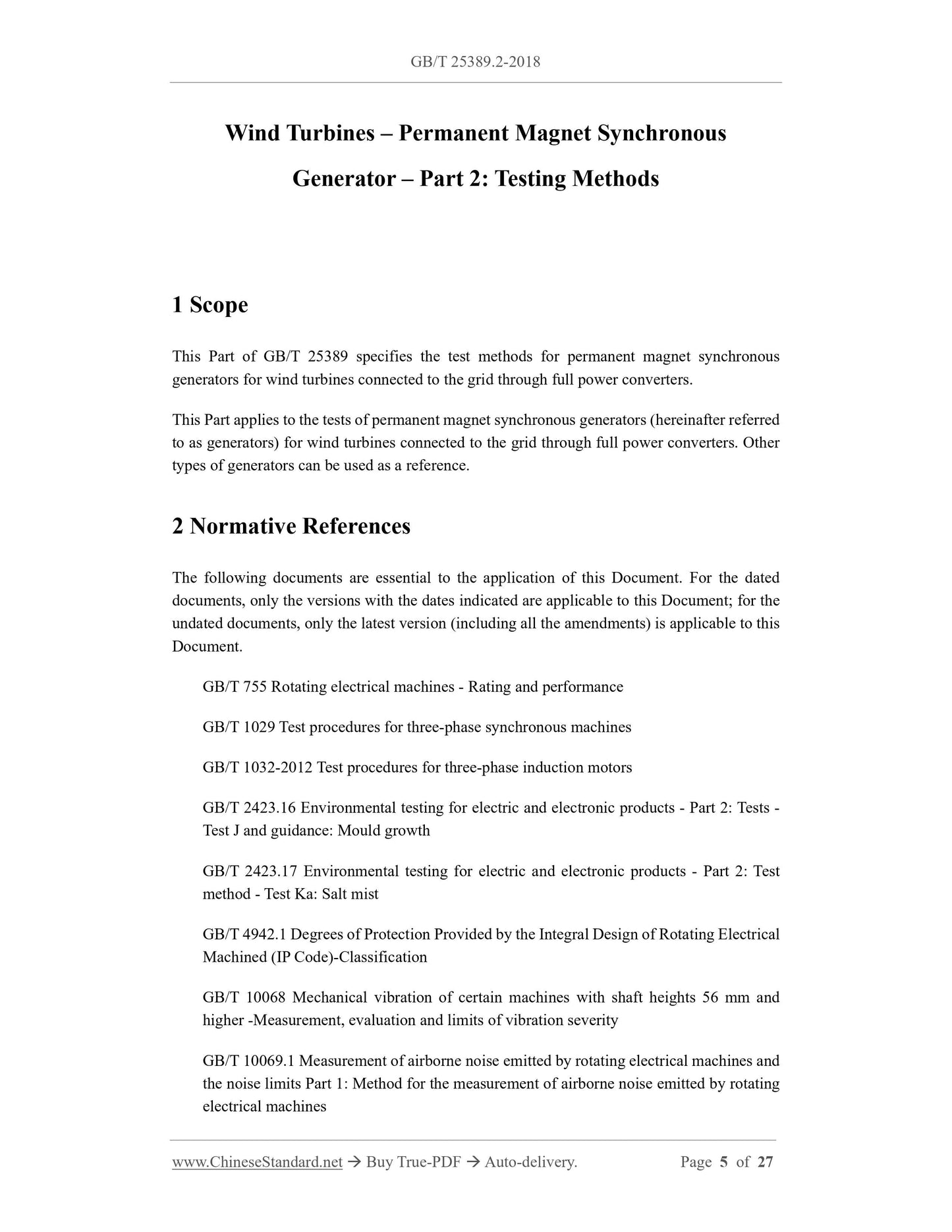
Wind Turbines – Permanent Magnet Synchronous
Generator – Part 2: Testing Methods
1 Scope
This Part of GB/T 25389 specifies the test methods for permanent magnet synchronous
generators for wind turbines connected to the grid through full power converters.
This Part applies to the tests of permanent magnet synchronous generators (hereinafter referred
to as generators) for wind turbines connected to the grid through full power converters. Other
types of generators can be used as a reference.
2 Normative References
The following documents are essential to the application of this Document. For the dated
documents, only the versions with the dates indicated are applicable to this Document; for the
undated documents, only the latest version (including all the amendments) is applicable to this
Document.
GB/T 755 Rotating electrical machines - Rating and performance
GB/T 1029 Test procedures for three-phase synchronous machines
GB/T 1032-2012 Test procedures for three-phase induction motors
GB/T 2423.16 Environmental testing for electric and electronic products - Part 2: Tests -
Test J and guidance: Mould growth
GB/T 2423.17 Environmental testing for electric and electronic products - Part 2: Test
method - Test Ka: Salt mist
GB/T 4942.1 Degrees of Protection Provided by the Integral Design of Rotating Electrical
Machined (IP Code)-Classification
GB/T 10068 Mechanical vibration of certain machines with shaft heights 56 mm and
higher -Measurement, evaluation and limits of vibration severity
GB/T 10069.1 Measurement of airborne noise emitted by rotating electrical machines and
the noise limits Part 1: Method for the measurement of airborne noise emitted by rotating
electrical machines
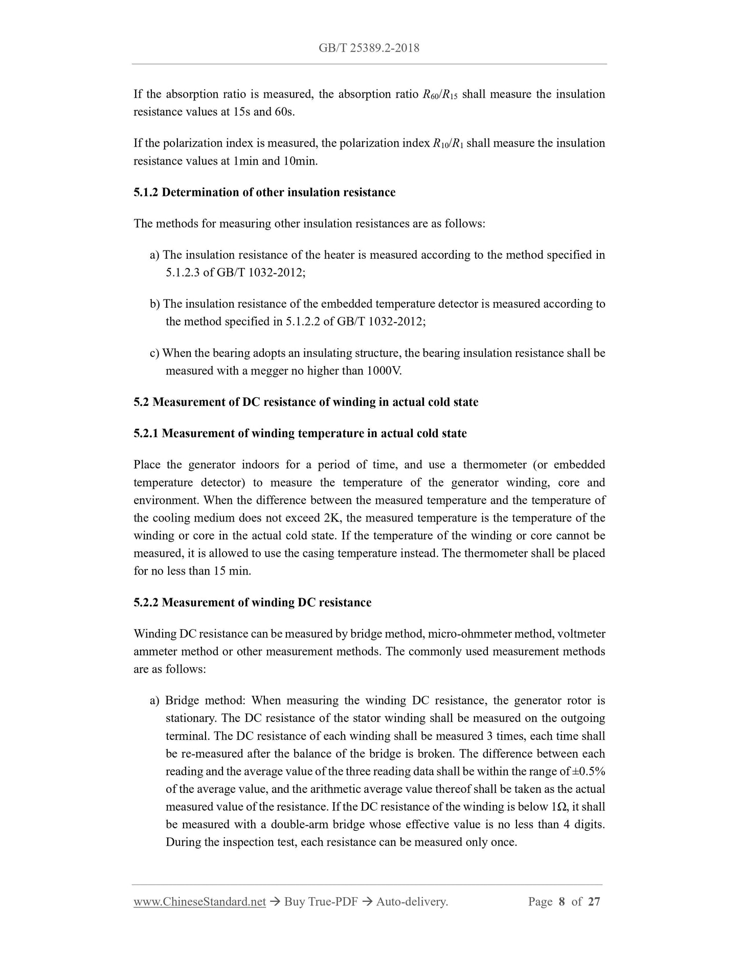
If the absorption ratio is measured, the absorption ratio R60/R15 shall measure the insulation
resistance values at 15s and 60s.
If the polarization index is measured, the polarization index R10/R1 shall measure the insulation
resistance values at 1min and 10min.
5.1.2 Determination of other insulation resistance
The methods for measuring other insulation resistances are as follows:
a) The insulation resistance of the heater is measured according to the method specified in
5.1.2.3 of GB/T 1032-2012;
b) The insulation resistance of the embedded temperature detector is measured according to
the method specified in 5.1.2.2 of GB/T 1032-2012;
c) When the bearing adopts an insulating structure, the bearing insulation resistance shall be
measured with a megger no higher than 1000V.
5.2 Measurement of DC resistance of winding in actual cold state
5.2.1 Measurement of winding temperature in actual cold state
Place the generator indoors for a period of time, and use a thermometer (or embedded
temperature detector) to measure the temperature of the generator winding, core and
environment. When the difference between the measured temperature and the temperature of
the cooling medium does not exceed 2K, the measured temperature is the temperature of the
winding or core in the actual cold state. If the temperature of the winding or core cannot be
measured, it is allowed to use the casing temperature instead. The thermometer shall be placed
for no less than 15 min.
5.2.2 Measurement of winding DC resistance
Winding DC resistance can be measured by bridge method, micro-ohmmeter method, voltmeter
ammeter method or other measurement methods. The commonly used measurement methods
are as follows:
a) Bridge method: When measuring the winding DC resistance, the generator rotor is
stationary. The DC resistance of the stator winding shall be measured on the outgoing
terminal. The DC resistance of each winding shall be measured 3 times, each time shall
be re-measured after the balance of the bridge is broken. The difference between each
reading and the average value of the three reading data shall be within the range of ±0.5%
of the average value, and the arithmetic average value thereof shall be taken as the actual
measured value of the resistance. If the DC resistance of the winding is below 1Ω, it shall
be measured with a double-arm bridge whose effective value is no less than 4 digits.
During the inspection test, each resistance can be measured only once.
the test adopts the single motor method or the generator method. The rotational speed during
the test shall be within the full rotational speed range of the type test and shall not exceed the
rated rotational speed.
5.7 Noise measurement
The measurement method of the generator noise shall be carried out in accordance with the
provisions of GB/T 10069.1; and the test shall adopt the single motor method or the generator
method.
5.8 Determination of generator voltage tolerance
The generator is driven by the tractor through the coupling to run at no-load at the rated speed,
and the stator winding is open. Use a voltage measuring instrument to measure the m-phase
voltage U at the output end of the generator. The percentage of the ratio of the m-phase voltage
U to the rated voltage on the generator nameplate, the upper and lower limit tolerances, and the
degree of unbalance are assessed according to corresponding standards or technical conditions.
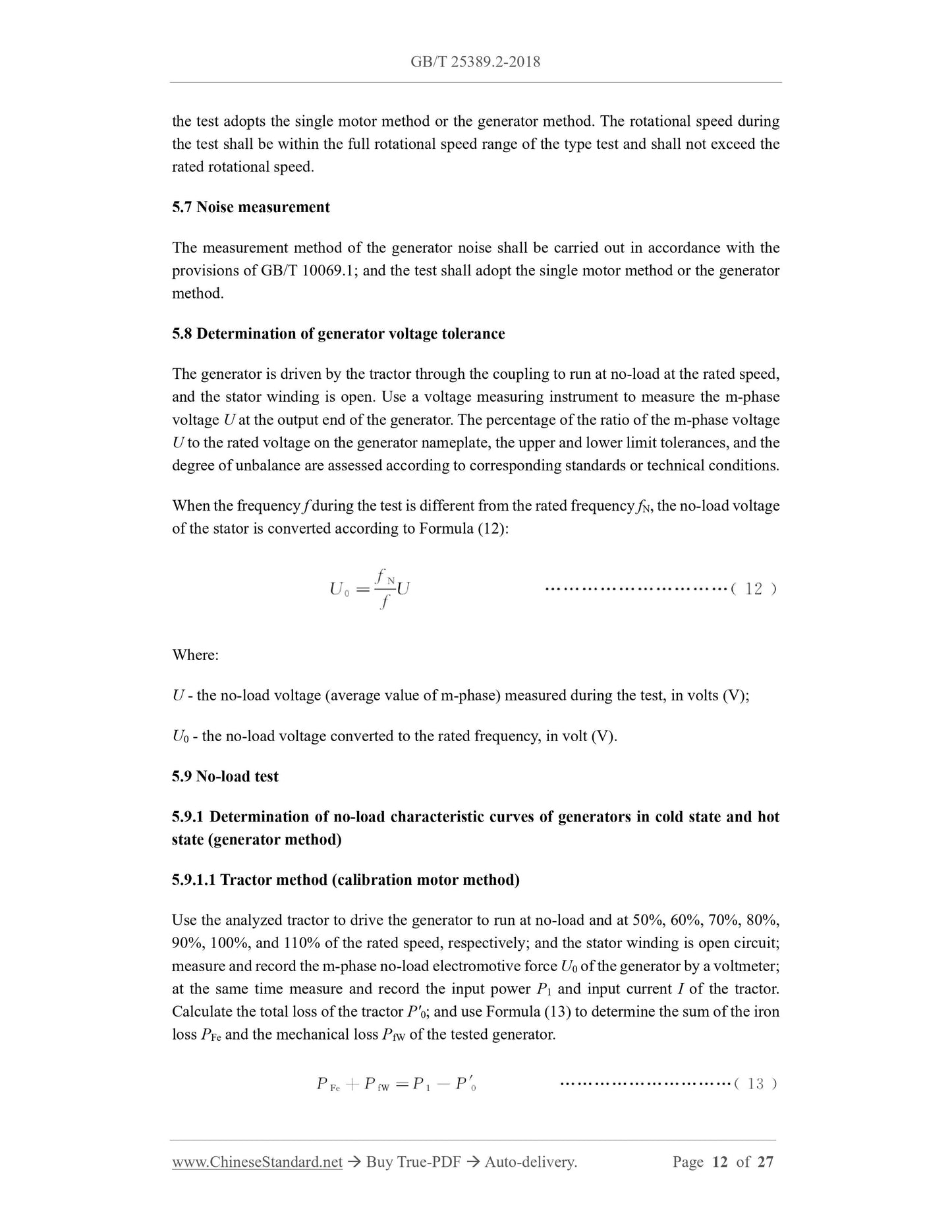
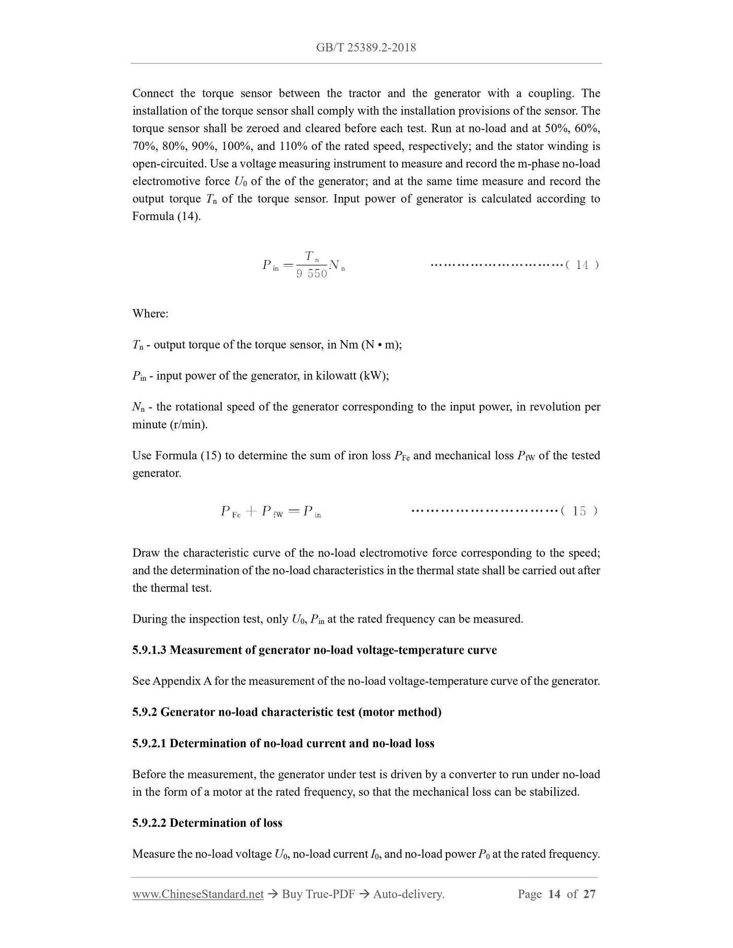
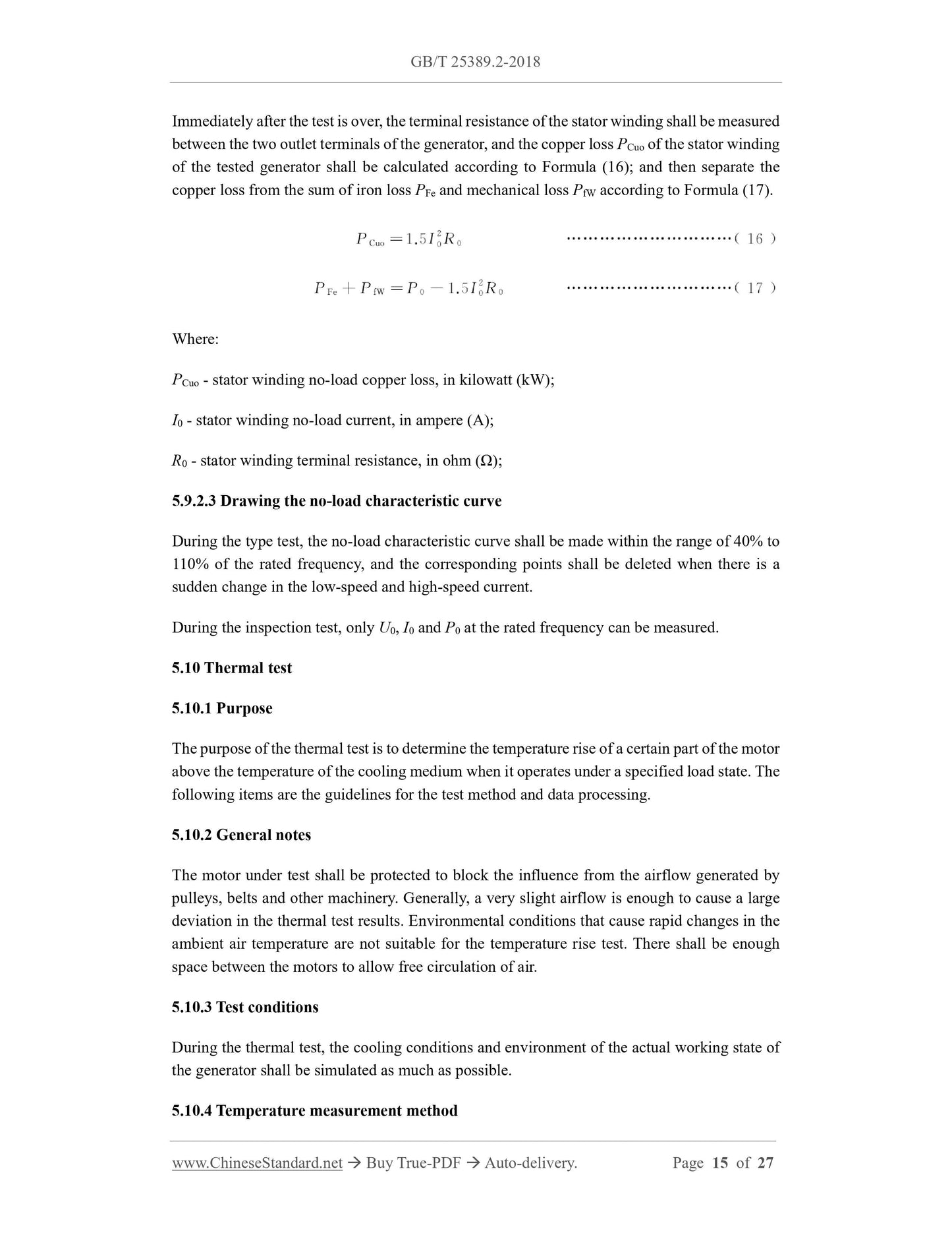
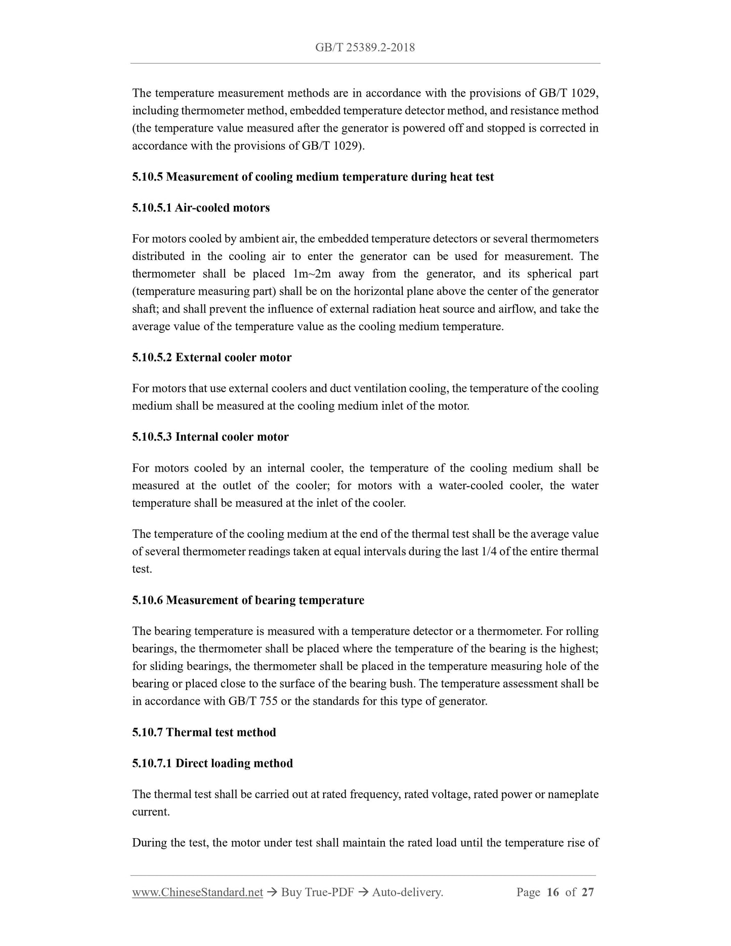
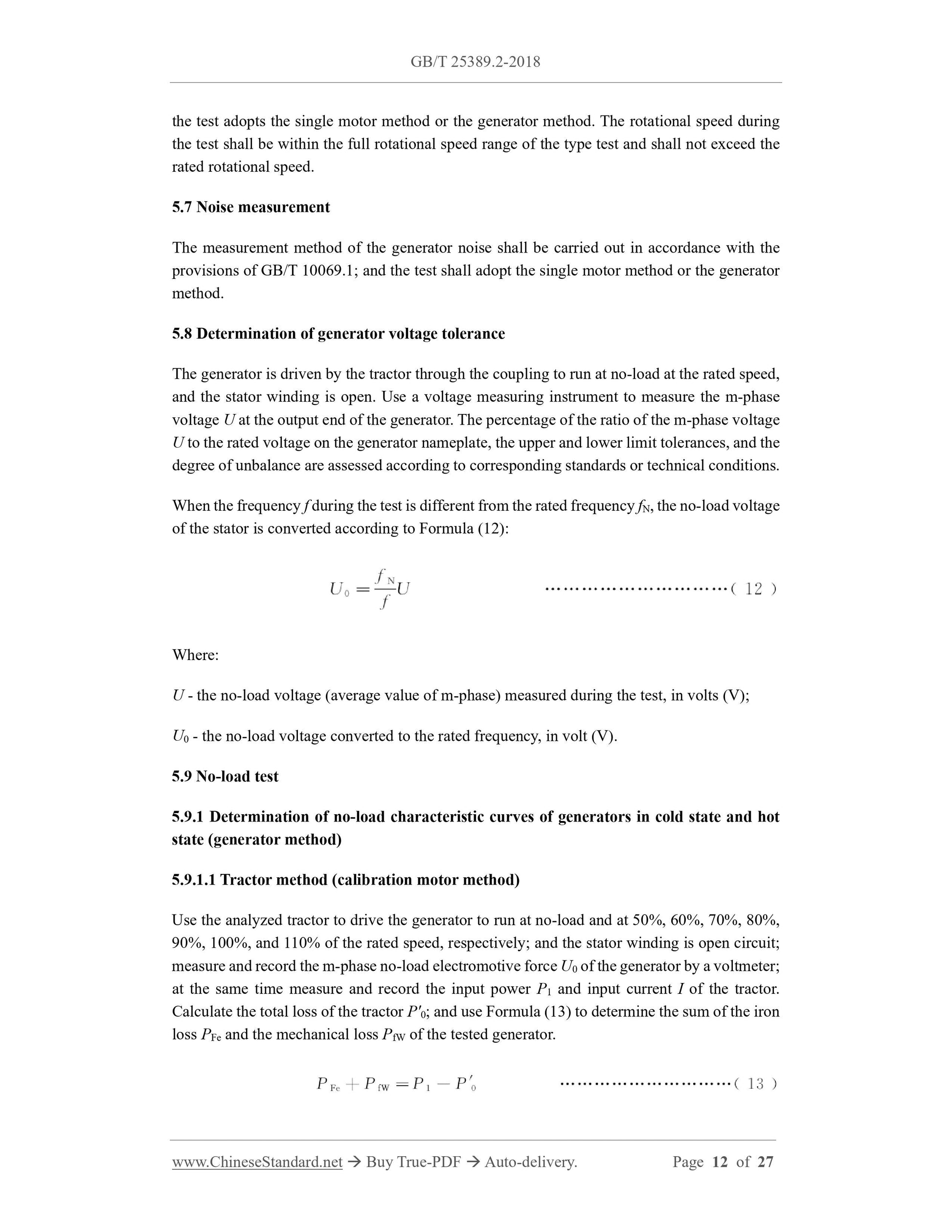
When the frequency f during the test is different from the rated frequency fN, the no-load voltage
of the stator is converted according to Formula (12):
Where:
U - the no-load voltage (average value of m-phase) measured during the test, in volts (V);
U0 - the no-load voltage converted to the rated frequency, in volt (V).
5.9 No-load test
5.9.1 Determination of no-load characteristic curves of generators in cold state and hot
state (generator method)
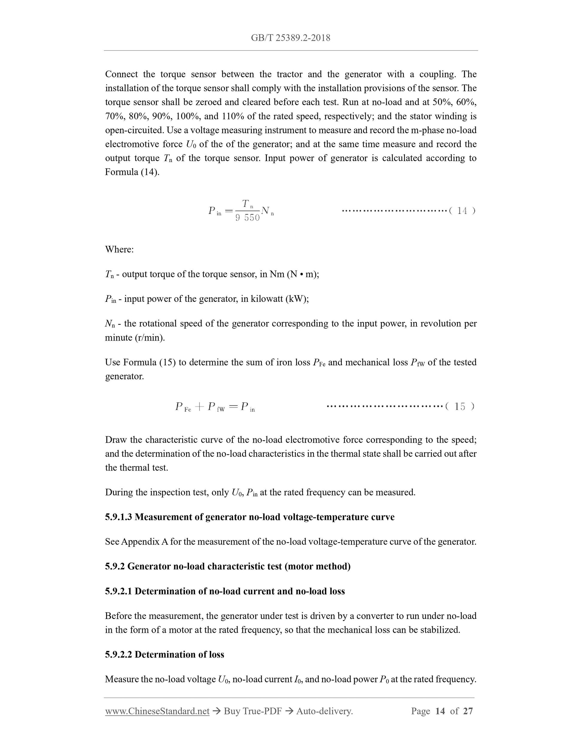
5.9.1.1 Tractor method (calibration motor method)
Use the analyzed tractor to drive the generator to r...