
1
/
of
5
www.ChineseStandard.us -- Field Test Asia Pte. Ltd.
GB/T 25085.3-2020 English PDF (GB/T25085.3-2020)
GB/T 25085.3-2020 English PDF (GB/T25085.3-2020)
Regular price
$215.00
Regular price
Sale price
$215.00
Unit price
/
per
Shipping calculated at checkout.
Couldn't load pickup availability
GB/T 25085.3-2020: Road vehicles--Automotive cables - Part 3: Dimensions and requirements for 30 V a. c. or 60 V d. c. single-core copper conductor cables
Delivery: 9 seconds. Download (and Email) true-PDF + Invoice.Get Quotation: Click GB/T 25085.3-2020 (Self-service in 1-minute)
Newer / historical versions: GB/T 25085.3-2020
Preview True-PDF
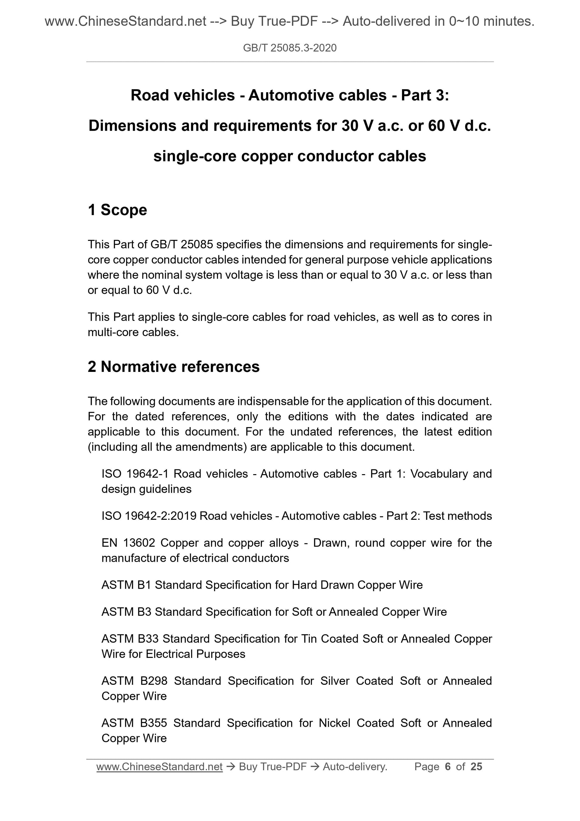
Scope
This part of GB/T 25085 specifies that the nominal system voltage for general-purpose road vehicles shall not exceed AC 30V or DC 60V.The size and requirements of core copper conductor cables.
This section applies to single-core cables for road vehicles and also applies to cores in multi-core cables.
Basic Data
| Standard ID | GB/T 25085.3-2020 (GB/T25085.3-2020) |
| Description (Translated English) | Road vehicles--Automotive cables - Part 3: Dimensions and requirements for 30 V a. c. or 60 V d. c. single-core copper conductor cables |
| Sector / Industry | National Standard (Recommended) |
| Classification of Chinese Standard | T36 |
| Classification of International Standard | 43.040.10 |
| Word Count Estimation | 22,282 |
| Date of Issue | 2020-06-02 |
| Date of Implementation | 2020-12-01 |
| Issuing agency(ies) | State Administration for Market Regulation, China National Standardization Administration |
Share