1
/
of
6
PayPal, credit cards. Download editable-PDF and invoice in 1 second!
GB/T 24524-2021 English PDF (GB/T24524-2021)
Regular price
$230.00
Regular price
Sale price
$230.00
Unit price
/
per
Shipping calculated at checkout.
Couldn't load pickup availability
GB/T 24524-2021: Metallic materials - Sheet and strip - Hole expanding test
Delivery: 9 seconds. Download (& Email) true-PDF + Invoice.
Get Quotation: Click GB/T 24524-2021 (Self-service in 1-minute)
Historical versions (Master-website): GB/T 24524-2021
Preview True-PDF (Reload/Scroll-down if blank)
GB/T 24524-2021
NATIONAL STANDARD OF THE
PEOPLE’S REPUBLIC OF CHINA
ICS 77.040.10
CCS H 23
Replacing GB/T 24524-2009
Metallic Materials – Sheet and Strip – Hole Expanding Test
(ISO 16630:2017, MOD)
ISSUED ON: AUGUST 20, 2021
IMPLEMENTED ON: MARCH 01, 2022
Issued by: State Administration for Market Regulation;
Standardization Administration of the People’s Republic of China.
Table of Contents
Foreword ... 3
Introduction ... 5
1 Scope ... 6
2 Normative References ... 6
3 Terms and Definitions ... 6
4 Symbol and Instruction ... 7
5 Principle ... 7
6 Test Equipment ... 9
7 Specimen ... 10
8 Test Procedures ... 12
9 Calculation of Test Results ... 13
10 Test Report ... 14
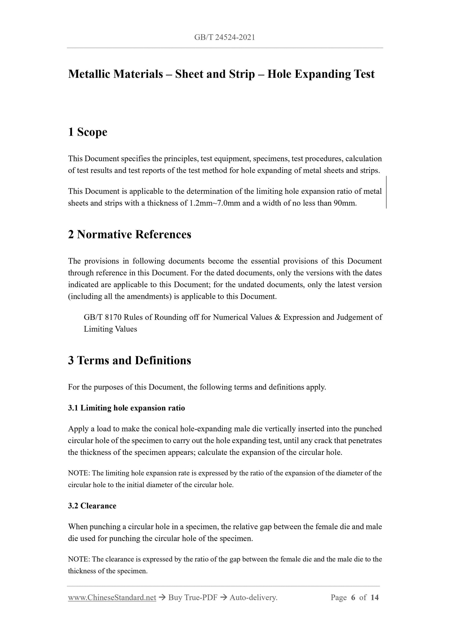
Metallic Materials – Sheet and Strip – Hole Expanding Test
1 Scope
This Document specifies the principles, test equipment, specimens, test procedures, calculation
of test results and test reports of the test method for hole expanding of metal sheets and strips.
This Document is applicable to the determination of the limiting hole expansion ratio of metal
sheets and strips with a thickness of 1.2mm~7.0mm and a width of no less than 90mm.
2 Normative References
The provisions in following documents become the essential provisions of this Document
through reference in this Document. For the dated documents, only the versions with the dates
indicated are applicable to this Document; for the undated documents, only the latest version
(including all the amendments) is applicable to this Document.
GB/T 8170 Rules of Rounding off for Numerical Values and Expression and Judgement of
Limiting Values
3 Terms and Definitions
For the purposes of this Document, the following terms and definitions apply.
3.1 Limiting hole expansion ratio
Apply a load to make the conical hole-expanding male die vertically inserted into the punched
circular hole of the specimen to carry out the hole expanding test, until any crack that penetrates
the thickness of the specimen appears; calculate the expansion of the circular hole.
NOTE: The limiting hole expansion rate is expressed by the ratio of the expansion of the diameter of the
circular hole to the initial diameter of the circular hole.
3.2 Clearance
When punching a circular hole in a specimen, the relative gap between the female die and male
die used for punching the circular hole of the specimen.
NOTE: The clearance is expressed by the ratio of the gap between the female die and the male die to the
thickness of the specimen.
2 – female die shoulder;
3 – female die;
4 – punching burr;
5 – crack;
6 – top angle of male die;
7 – male die.
Figure 2 – Schematic Diagram of Hole-Expanding Test
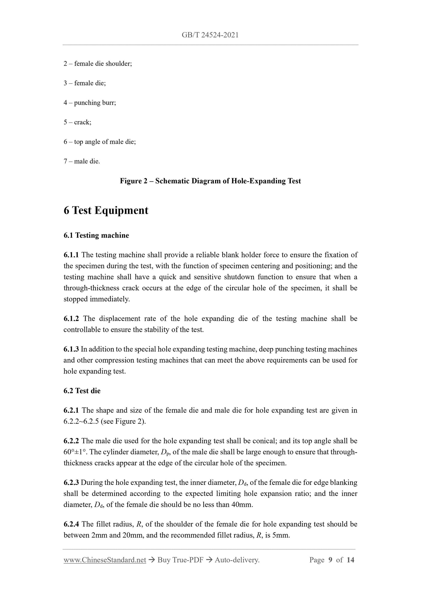
6 Test Equipment
6.1 Testing machine
6.1.1 The testing machine shall provide a reliable blank holder force to ensure the fixation of
the specimen during the test, with the function of specimen centering and positioning; and the
testing machine shall have a quick and sensitive shutdown function to ensure that when a
through-thickness crack occurs at the edge of the circular hole of the specimen, it shall be
stopped immediately.
6.1.2 The displacement rate of the hole expanding die of the testing machine shall be
controllable to ensure the stability of the test.
6.1.3 In addition to the special hole expanding testing machine, deep punching testing machines
and other compression testing machines that can meet the above requirements can be used for
hole expanding test.
6.2 Test die
6.2.1 The shape and size of the female die and male die for hole expanding test are given in
6.2.2~6.2.5 (see Figure 2).
6.2.2 The male die used for the hole expanding test shall be conical; and its top angle shall be
60°±1°. The cylinder diameter, Dp, of the male die shall be large enough to ensure that through-
thickness cracks appear at the edge of the circular hole of the specimen.
6.2.3 During the hole expanding test, the inner diameter, Dd, of the female die for edge blanking
shall be determined according to the expected limiting hole expansion ratio; and the inner
diameter, Dd, of the female die should be no less than 40mm.
6.2.4 The fillet radius, R, of the shoulder of the female die for hole expanding test should be
between 2mm and 20mm, and the recommended fillet radius, R, is 5mm.
7.6 During the punching process of the specimen, the punching male die and the punching
female die should be kept coaxial; and the axis of the punching male die shall be perpendicular
to the surface of the specimen.
8 Test Procedures
8.1 The test is generally carried out at room temperature within the range of 10°C ~ 35°C. For
tests with strict temperature requirements, the test temperature shall be 23°C ± 5°C.
8.2 Normally, the same blank shall be tested for 3 times. The number of tests may also be
increased with the consent of the interested parties.
8.3 Place the burrs of the punched circular hole toward the female die hole; and place the
specimen flat on the hole expanding die; so that the center of the punched circular hole of the
specimen is consistent with the axis of the conical hole expanding male die, and the plane of
the specimen is perpendicular to the axis of the hole expanding male die (see Figure 2); so as
to keep the hole expanding direction consistent with the punching direction.
8.4 Apply a large enough blank holder force to the specimen to clamp the specimen to ensure
that the specimen material does not deform and flow in the clamping area during the test.
EXAMPLE: For a 150mm×150mm specimen, the blank holder force is generally no less than 50kN.
If deformation flow occurs in the clamping area, the test shall be invalid and the test shall be
repeated.
8.5 Apply pressure so that the conical hole expanding male die is inserted vertically into the
punched circular hole of the specimen at a certain rate for hole expanding (see Figure 2); and
the rate shall be able to ensure that the tester stops the test when the first through-thickness
crack appears. The advancing speed of the conical hole expanding male die should not exceed
1mm/s.
8.6 During the test, it shall be ensured that the edge of the hole is constantly being monitored;
and when a microcrack occurs for the first time, the advancing rate of the hole expanding male
die shall be slowed down immediately; so that the increments of hole diameter shall be reduced
as much as possible within the time from the occurrence of the microcrack to the stop of the
male die movement.
8.7 When a through-thickness crack occurs, immediately stop the advance of the hole
expanding male die and return the male die. Use a suitable measuring tool or method, such as
a calibrated projector, feeler gauge, etc., to measure the crack width inside the opening of the
through-thickness crack after the specimen is broken; and its maximum width should not
exceed 0.1mm. Use a vernier caliper or other suitable measuring tool (such as a calibrated
projector) to measure the inner diameter of the circular hole after the specimen is broken,
accurate to 0.05mm. During the measurement, the position of the crack shall be avoided, and
the inner diameter of the circular hole shall be measured in two mutually perpendicular
directions.
8.8 For some designations (grades) of steel, the cylindrical part of the hole expanding male die
may pass through the circular hole after the specimen is expanded, and the edge of the circular
hole does not appear crack. At this point, the test is invalid. The conical hole expanding male
die with larger diameter shall be re-selected for the test. If there is no hole expanding die with
a larger diameter, the diameter of the punched circular hole may be reduced and re-tested under
the premise of the consent of the relevant parties.
9 Calculation of Test Results
9.1 The limiting hole expansion ratio, λ, shall be calculated according to the provisions of
9.2~9.4.
9.2 Use the inner diameters of two mutually perpendicular circular holes measured in 8.7 to
determine the average diameter of the circular holes after rupture.
9.3 Calculate the limiting hole expansion ratio of each sample in the test for 3 times (or more,
see 8.2) according to Formula (2) with the average diameter retained to one digit after decimal
point.
9.4 Calculate the average limiting hole expansion ratio, , based on the test results of 3 (or
more, see 8.2) tests in 9.3, rounded-off to an integer (intervals of 1%). The numerical rounding
GB/T 24524-2021
NATIONAL STANDARD OF THE
PEOPLE’S REPUBLIC OF CHINA
ICS 77.040.10
CCS H 23
Replacing GB/T 24524-2009
Metallic Materials – Sheet and Strip – Hole Expanding Test
(ISO 16630:2017, MOD)
ISSUED ON: AUGUST 20, 2021
IMPLEMENTED ON: MARCH 01, 2022
Issued by: State Administration for Market Regulation;
Standardization Administration of the People’s Republic of China.
Table of Contents
Foreword ... 3
Introduction ... 5
1 Scope ... 6
2 Normative References ... 6
3 Terms and Definitions ... 6
4 Symbol and Instruction ... 7
5 Principle ... 7
6 Test Equipment ... 9
7 Specimen ... 10
8 Test Procedures ... 12
9 Calculation of Test Results ... 13
10 Test Report ... 14
Metallic Materials – Sheet and Strip – Hole Expanding Test
1 Scope
This Document specifies the principles, test equipment, specimens, test procedures, calculation
of test results and test reports of the test method for hole expanding of metal sheets and strips.
This Document is applicable to the determination of the limiting hole expansion ratio of metal
sheets and strips with a thickness of 1.2mm~7.0mm and a width of no less than 90mm.
2 Normative References
The provisions in following documents become the essential provisions of this Document
through reference in this Document. For the dated documents, only the versions with the dates
indicated are applicable to this Document; for the undated documents, only the latest version
(including all the amendments) is applicable to this Document.
GB/T 8170 Rules of Rounding off for Numerical Values and Expression and Judgement of
Limiting Values
3 Terms and Definitions
For the purposes of this Document, the following terms and definitions apply.
3.1 Limiting hole expansion ratio
Apply a load to make the conical hole-expanding male die vertically inserted into the punched
circular hole of the specimen to carry out the hole expanding test, until any crack that penetrates
the thickness of the specimen appears; calculate the expansion of the circular hole.
NOTE: The limiting hole expansion rate is expressed by the ratio of the expansion of the diameter of the
circular hole to the initial diameter of the circular hole.
3.2 Clearance
When punching a circular hole in a specimen, the relative gap between the female die and male
die used for punching the circular hole of the specimen.
NOTE: The clearance is expressed by the ratio of the gap between the female die and the male die to the
thickness of the specimen.
2 – female die shoulder;
3 – female die;
4 – punching burr;
5 – crack;
6 – top angle of male die;
7 – male die.
Figure 2 – Schematic Diagram of Hole-Expanding Test
6 Test Equipment
6.1 Testing machine
6.1.1 The testing machine shall provide a reliable blank holder force to ensure the fixation of
the specimen during the test, with the function of specimen centering and positioning; and the
testing machine shall have a quick and sensitive shutdown function to ensure that when a
through-thickness crack occurs at the edge of the circular hole of the specimen, it shall be
stopped immediately.
6.1.2 The displacement rate of the hole expanding die of the testing machine shall be
controllable to ensure the stability of the test.
6.1.3 In addition to the special hole expanding testing machine, deep punching testing machines
and other compression testing machines that can meet the above requirements can be used for
hole expanding test.
6.2 Test die
6.2.1 The shape and size of the female die and male die for hole expanding test are given in
6.2.2~6.2.5 (see Figure 2).
6.2.2 The male die used for the hole expanding test shall be conical; and its top angle shall be
60°±1°. The cylinder diameter, Dp, of the male die shall be large enough to ensure that through-
thickness cracks appear at the edge of the circular hole of the specimen.
6.2.3 During the hole expanding test, the inner diameter, Dd, of the female die for edge blanking
shall be determined according to the expected limiting hole expansion ratio; and the inner
diameter, Dd, of the female die should be no less than 40mm.
6.2.4 The fillet radius, R, of the shoulder of the female die for hole expanding test should be
between 2mm and 20mm, and the recommended fillet radius, R, is 5mm.
7.6 During the punching process of the specimen, the punching male die and the punching
female die should be kept coaxial; and the axis of the punching male die shall be perpendicular
to the surface of the specimen.
8 Test Procedures
8.1 The test is generally carried out at room temperature within the range of 10°C ~ 35°C. For
tests with strict temperature requirements, the test temperature shall be 23°C ± 5°C.
8.2 Normally, the same blank shall be tested for 3 times. The number of tests may also be
increased with the consent of the interested parties.
8.3 Place the burrs of the punched circular hole toward the female die hole; and place the
specimen flat on the hole expanding die; so that the center of the punched circular hole of the
specimen is consistent with the axis of the conical hole expanding male die, and the plane of
the specimen is perpendicular to the axis of the hole expanding male die (see Figure 2); so as
to keep the hole expanding direction consistent with the punching direction.
8.4 Apply a large enough blank holder force to the specimen to clamp the specimen to ensure
that the specimen material does not deform and flow in the clamping area during the test.
EXAMPLE: For a 150mm×150mm specimen, the blank holder force is generally no less than 50kN.
If defo...
Share