PayPal, credit cards. Download editable-PDF and invoice in 1 second!
Regular price
$145.00
Regular price
Sale price
$145.00
Unit price
/
per
Couldn't load pickup availability
GB/T 2423.5-1995: Environmental testing for electric and electronic products - Part 2: Test methods - Test Ea and guidance: Shock
Delivery: 9 seconds. Download (and Email) true-PDF + Invoice.
Get Quotation: Click
GB/T 2423.5-1995 (Self-service in 1-minute)
Newer / historical versions: GB/T 2423.5-1995Preview True-PDF
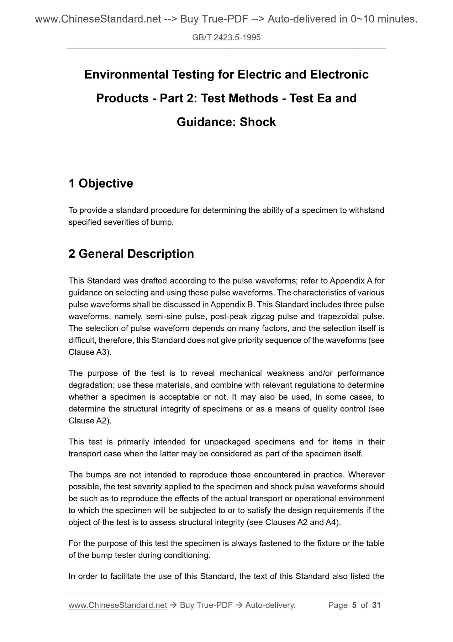
Scope
To provide a standard procedure for determining the ability of a specimen to withstand
specified severities of bump.
Basic Data
| Standard ID | GB/T 2423.5-1995 (GB/T2423.5-1995) |
| Description (Translated English) | Environmental testing for electric and electronic products - Part 2: Test methods - Test Ea and guidance: Shock |
| Sector / Industry | National Standard (Recommended) |
| Classification of Chinese Standard | K04 |
| Classification of International Standard | 19.04 |
| Word Count Estimation | 19,132 |
| Date of Issue | 8/29/1995 |
| Date of Implementation | 8/1/1996 |
| Older Standard (superseded by this standard) | GB 2423.5-1981; GB 2424.3-1981 |
| Adopted Standard | IEC 60068-2-27-1987, IDT |
| Issuing agency(ies) | State Bureau of Technical Supervision |
Share
View full details