Skip to product information
1 of 10

PayPal, credit cards. Download editable-PDF & invoice In 1 second!

GB/T 23931-2021 English PDF (GBT23931-2021)

GB/T 23931-2021 English PDF (GBT23931-2021)

Regular price $290.00 USD
Regular price Sale price $290.00 USD
Sale Sold out
Shipping calculated at checkout.
Quotation: In 1-minute, 24-hr self-service. Click here GB/T 23931-2021 to get it for Purchase Approval, Bank TT...

GB/T 23931-2021: Tri-wheel Vehicles - Test Method

This document specifies the test methods for determining various performances of complete tri-wheel vehicles. This document is applicable to the complete-vehicle test of tri-wheel vehicles.
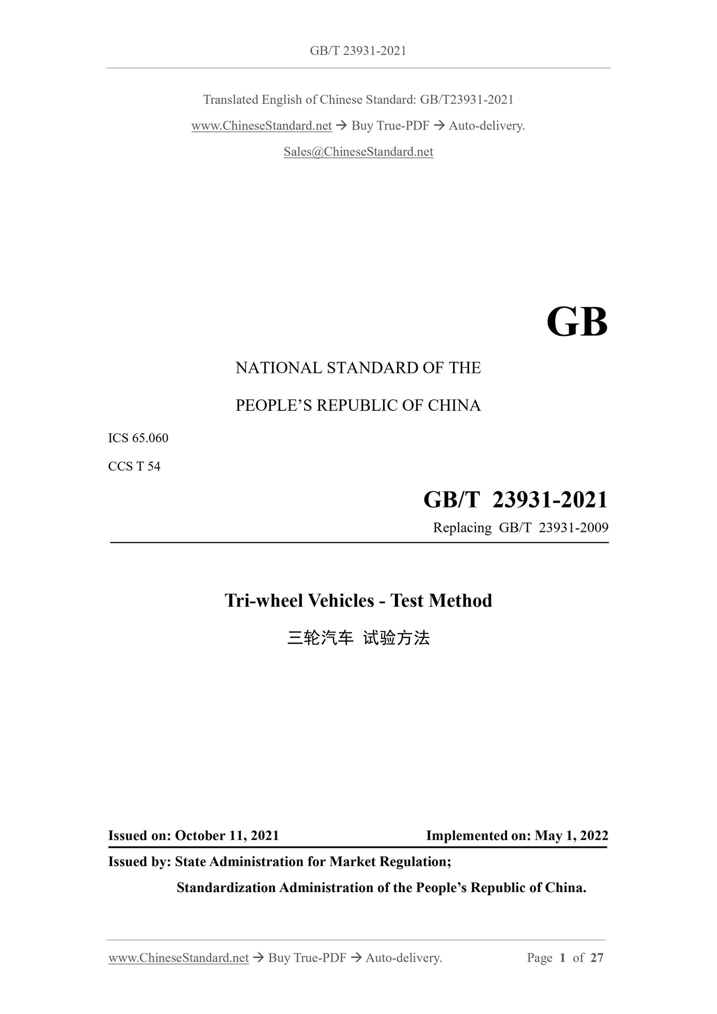
GB/T 23931-2021
GB
NATIONAL STANDARD OF THE
PEOPLE’S REPUBLIC OF CHINA
ICS 65.060
CCS T 54
Replacing GB/T 23931-2009
Tri-wheel Vehicles - Test Method
ISSUED ON: OCTOBER 11, 2021
IMPLEMENTED ON: MAY 1, 2022
Issued by: State Administration for Market Regulation;
Standardization Administration of the People’s Republic of China.
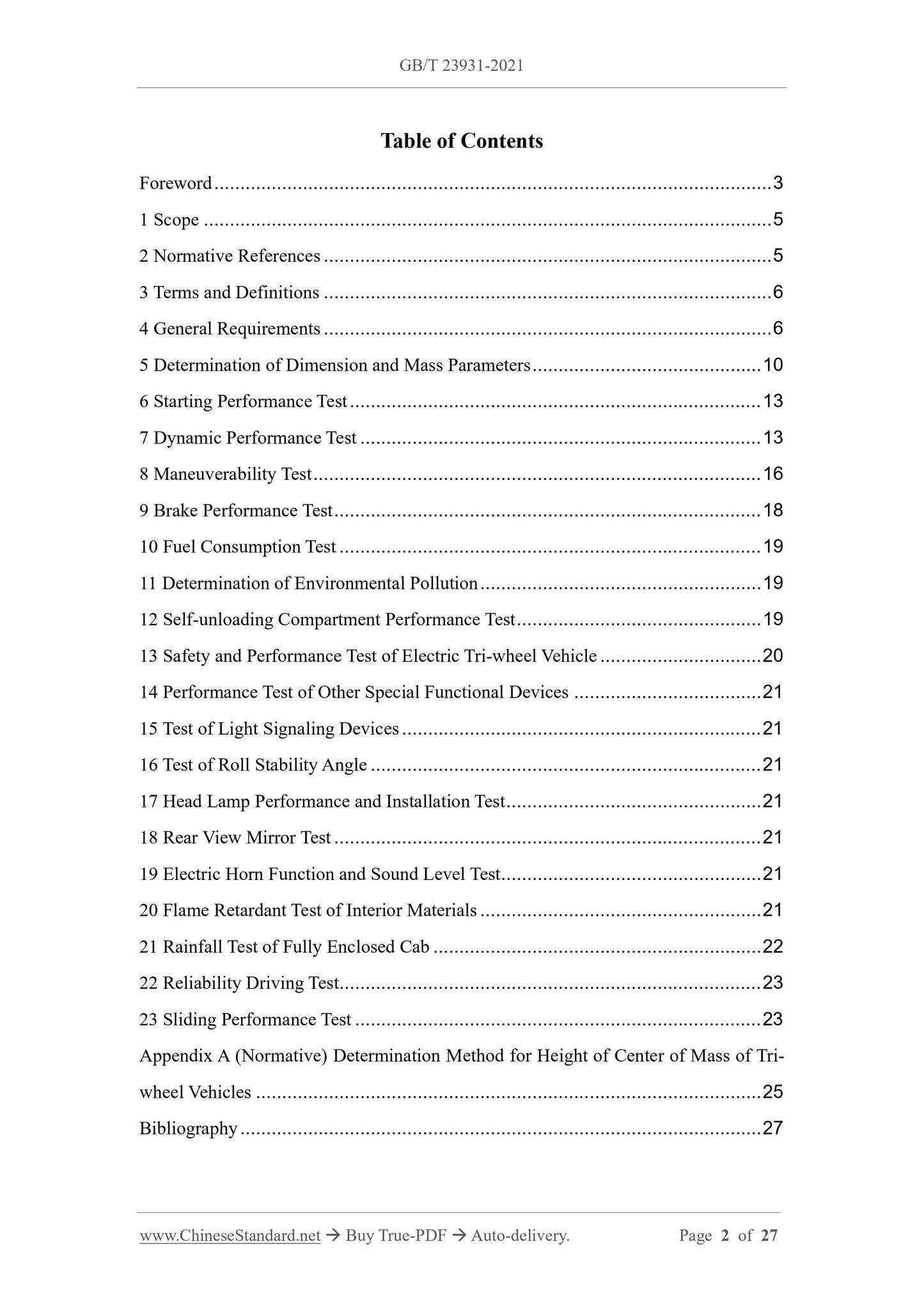
Table of Contents
Foreword ... 3
1 Scope ... 5
2 Normative References ... 5
3 Terms and Definitions ... 6
4 General Requirements ... 6
5 Determination of Dimension and Mass Parameters ... 10
6 Starting Performance Test ... 13
7 Dynamic Performance Test ... 13
8 Maneuverability Test ... 16
9 Brake Performance Test ... 18
10 Fuel Consumption Test ... 19
11 Determination of Environmental Pollution ... 19
12 Self-unloading Compartment Performance Test ... 19
13 Safety and Performance Test of Electric Tri-wheel Vehicle ... 20
14 Performance Test of Other Special Functional Devices ... 21
15 Test of Light Signaling Devices ... 21
16 Test of Roll Stability Angle ... 21
17 Head Lamp Performance and Installation Test ... 21
18 Rear View Mirror Test ... 21
19 Electric Horn Function and Sound Level Test ... 21
20 Flame Retardant Test of Interior Materials ... 21
21 Rainfall Test of Fully Enclosed Cab ... 22
22 Reliability Driving Test... 23
23 Sliding Performance Test ... 23
Appendix A (Normative) Determination Method for Height of Center of Mass of Tri- wheel Vehicles ... 25
Bibliography ... 27
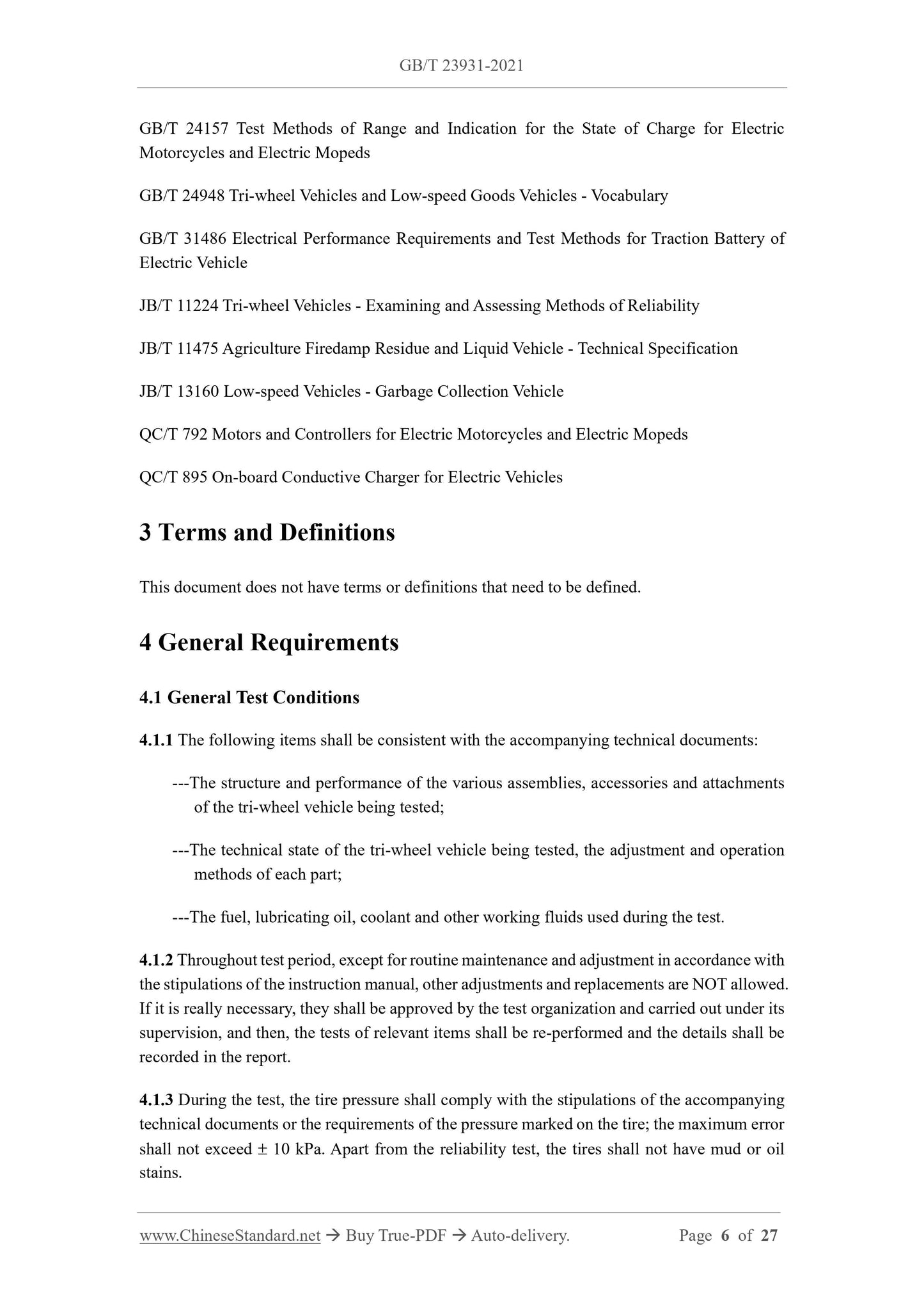
GB/T 24157 Test Methods of Range and Indication for the State of Charge for Electric Motorcycles and Electric Mopeds
GB/T 24948 Tri-wheel Vehicles and Low-speed Goods Vehicles - Vocabulary GB/T 31486 Electrical Performance Requirements and Test Methods for Traction Battery of Electric Vehicle
JB/T 11224 Tri-wheel Vehicles - Examining and Assessing Methods of Reliability JB/T 11475 Agriculture Firedamp Residue and Liquid Vehicle - Technical Specification JB/T 13160 Low-speed Vehicles - Garbage Collection Vehicle
QC/T 792 Motors and Controllers for Electric Motorcycles and Electric Mopeds QC/T 895 On-board Conductive Charger for Electric Vehicles
3 Terms and Definitions
This document does not have terms or definitions that need to be defined. 4 General Requirements
4.1 General Test Conditions
4.1.1 The following items shall be consistent with the accompanying technical documents: ---The structure and performance of the various assemblies, accessories and attachments of the tri-wheel vehicle being tested;
---The technical state of the tri-wheel vehicle being tested, the adjustment and operation methods of each part;
---The fuel, lubricating oil, coolant and other working fluids used during the test. 4.1.2 Throughout test period, except for routine maintenance and adjustment in accordance with the stipulations of the instruction manual, other adjustments and replacements are NOT allowed. If it is really necessary, they shall be approved by the test organization and carried out under its supervision, and then, the tests of relevant items shall be re-performed and the details shall be recorded in the report.
4.1.3 During the test, the tire pressure shall comply with the stipulations of the accompanying technical documents or the requirements of the pressure marked on the tire; the maximum error shall not exceed  10 kPa. Apart from the reliability test, the tires shall not have mud or oil stains.
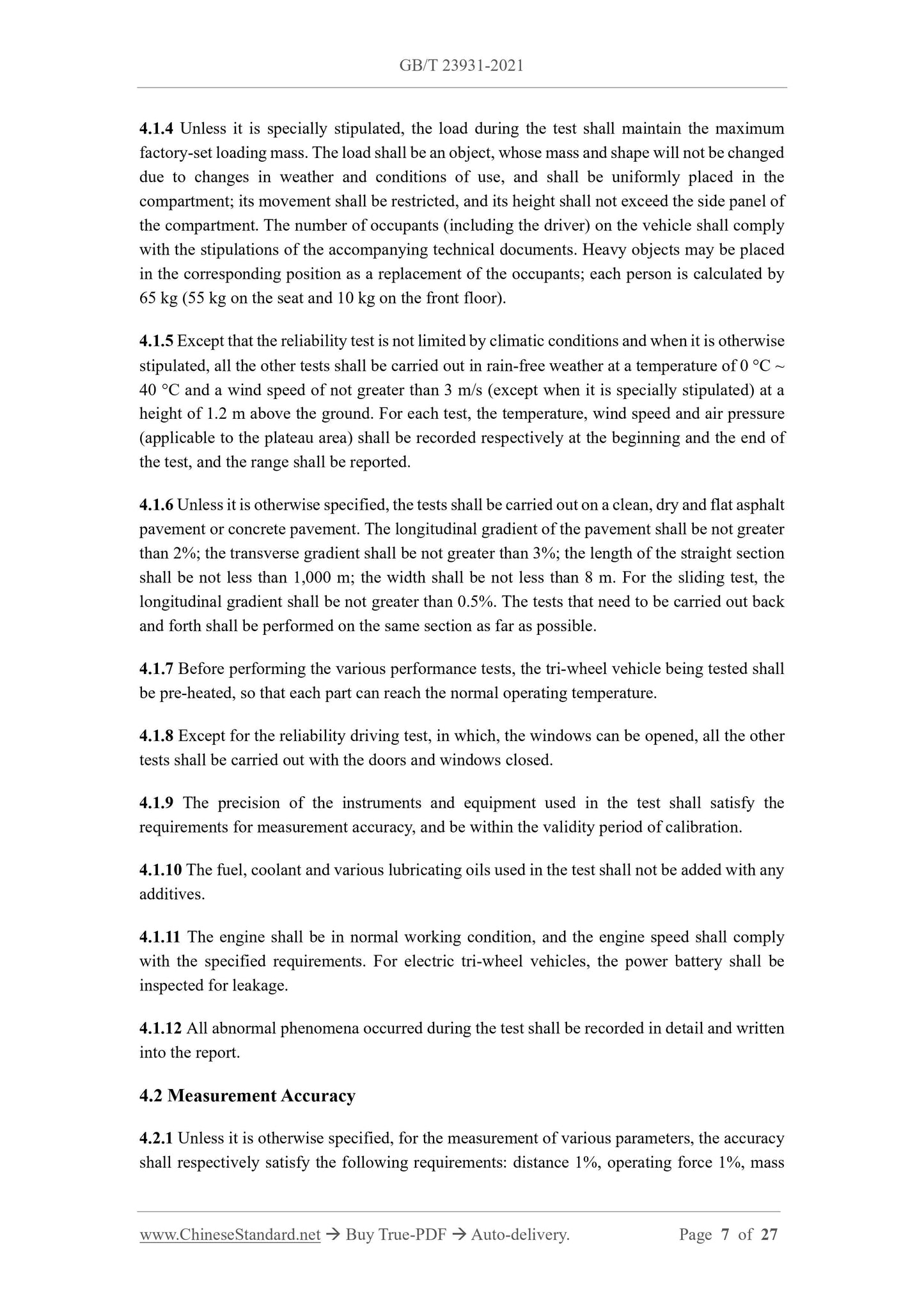
4.1.4 Unless it is specially stipulated, the load during the test shall maintain the maximum factory-set loading mass. The load shall be an object, whose mass and shape will not be changed due to changes in weather and conditions of use, and shall be uniformly placed in the compartment; its movement shall be restricted, and its height shall not exceed the side panel of the compartment. The number of occupants (including the driver) on the vehicle shall comply with the stipulations of the accompanying technical documents. Heavy objects may be placed in the corresponding position as a replacement of the occupants; each person is calculated by 65 kg (55 kg on the seat and 10 kg on the front floor).
4.1.5 Except that the reliability test is not limited by climatic conditions and when it is otherwise stipulated, all the other tests shall be carried out in rain-free weather at a temperature of 0 C ~ 40 C and a wind speed of not greater than 3 m/s (except when it is specially stipulated) at a height of 1.2 m above the ground. For each test, the temperature, wind speed and air pressure (applicable to the plateau area) shall be recorded respectively at the beginning and the end of the test, and the range shall be reported.
4.1.6 Unless it is otherwise specified, the tests shall be carried out on a clean, dry and flat asphalt pavement or concrete pavement. The longitudinal gradient of the pavement shall be not greater than 2%; the transverse gradient shall be not greater than 3%; the length of the straight section shall be not less than 1,000 m; the width shall be not less than 8 m. For the sliding test, the longitudinal gradient shall be not greater than 0.5%. The tests that need to be carried out back and forth shall be performed on the same section as far as possible.
4.1.7 Before performing the various performance tests, the tri-wheel vehicle being tested shall be pre-heated, so that each part can reach the normal operating temperature. 4.1.8 Except for the reliability driving test, in which, the windows can be opened, all the other tests shall be carried out with the doors and windows closed.
4.1.9 The precision of the instruments and equipment used in the test shall satisfy the requirements for measurement accuracy, and be within the validity period of calibration. 4.1.10 The fuel, coolant and various lubricating oils used in the test shall not be added with any additives.
4.1.11 The engine shall be in normal working condition, and the engine speed shall comply with the specified requirements. For electric tri-wheel vehicles, the power battery shall be inspected for leakage.
4.1.12 All abnormal phenomena occurred during the test shall be recorded in detail and written into the report.
4.2 Measurement Accuracy
4.2.1 Unless it is otherwise specified, for the measurement of various parameters, the accuracy shall respectively satisfy the following requirements: distance 1%, operating force 1%, mass on the accelerator pedal to accelerate the driving. During this period, the engine shall not be turned off, and the transmission system shall not vibrate. If the above-mentioned situation occurs, then, the vehicle speed shall be appropriately increased, and the test shall be re- performed. Repeat the test, until the minimum stable vehicle speed, at which, the tri-wheel vehicle being tested can smoothly accelerate, is found. In the state of the minimum stable vehicle speed, respectively carry out the test once back and forth; measure and record the distance and time of passing through the test area; calculate the minimum stable vehicle speed and take the arithmetic mean value.
Then, use the same method to test the minimum stable vehicle speed of the top gear when the tri-wheel vehicle being tested is in the top gear.
7.2 Determination of Maximum Vehicle Speed
The determination of the maximum vehicle speed shall be conducted in accordance with the stipulations of GB/T 23920.
7.3 Acceleration Performance Test
The tri-wheel vehicle being tested is in the top gear, and runs at a speed about 10% higher than the minimum stable vehicle speed of the gear. After the speed becomes stable, quickly step on the accelerator to the bottom, until the tri-wheel vehicle being tested is accelerated to above 80% of its maximum vehicle speed. Use the fifth wheel instrument (or other vehicle speed tester) to continuously record the entire acceleration process; measure and record the speed, time and distance. Respectively carry out the test once back and forth; take the average value of the two measured values at the same speed as the measurement result at the vehicle speed. The error of the two measured values of the initial speed and final speed back and forth test shall be not greater than 3 km/h.
7.4 Determination of Steep Hill Climbing Capacity
Select a section of road with a gradient close to the maximum steep hill climbing capacity (design value) of the tri-wheel vehicle being tested, a uniform gradient, a sufficient length of gradient and a flat or smooth straight ramp at the bottom as the test road. On the ramp, set up a length of 25 m as the speed measuring area. The starting point of the measuring area is 20 m away from the bottom of the slope. The measurement of the gradient shall be conducted at three representative locations at the beginning, the end and the middle sections of the ramp; take the average value.
During the test, after the tri-wheel vehicle being tested starts in the lowest gear from the flat road section about 20 m from the bottom of the slope, immediately step on the accelerator to the bottom and drive up to the ramp; measure the time of passing through the test area. If the vehicle fails to climb up the ramp and is forced to stop, reduce the load and re-perform the test. If the gradient of the test road is not suitable (large or small), the method of changing the load or changing the gear may be adopted for repeated tests, until about 50 kg is reduced or increased The tri-wheel vehicle drives with no-load, in the lowest gear and at a stable low speed. The steering wheel (or steering handle) is turned to the limit position in one direction. Meanwhile, on the ground, mark the contact point between the symmetrical center plane of the front wheel and the ground. After driving a full circle, exit the test site. Use a tape to measure the diameter of the trajectory circle in the three evenly distributed directions; take the average value. The measurement shall respectively be carried out in two directions: to the left and to the right. Respectively measure twice; take the average value. Take the greater value between the left- turning and the right-turning as the minimum turning circle diameter of the vehicle. 8.2 Maximum Free Angle Measurement of Steering Wheel
8.2.1 The vehicle being tested is stationary. The directive wheel is in a straight-line driving state. 8.2.2 Respectively turn the steering wheel to the left and the right, until the resistance significantly increases (the directive wheel starts to rotate); measure the angle of the steering wheel.
8.3 Directive Wheel Angle Measurement
8.3.1 The vehicle being tested is stationary. The directive wheel is in a straight-line driving state. 8.3.2 Respectively turn the steering wheel (steering handle) to the left and the right to the limit position; determine the angle of the directive wheel.
8.4 Measurement of Operating Force
8.4.1 Measurement of operating force of brake, clutch and other control levers The measurement of operating force of the various control mechanisms is carried out through different types of dynamometers. During the measurement, the tri-wheel vehicle being tested is in a stationary state; respectively measure the minimum operating force required to smoothly move the various control mechanisms to their working positions. The acting point is the midpoint of the driver’s routine operating position.
8.4.2 Measurement of steering force
Firstly, draw the driving route shown in Figure 1 on the test site. During the measurement, the tri-wheel vehicle starts from Point A at a speed of 10 km/h; its front wheel runs along the curve ABCD. Measure the maximum operating force acting on the steering wheel of the tri-wheel vehicle being tested while it drives from Point B to Point C. The measurement shall respectively be carried out three times in the two cases of right-turning and left-turning; respectively take the average value. When turning left, it shall drive along a route symmetrical to the X axis in Figure 1.
9.2 Parking Brake Performance
The tri-wheel vehicle (with no-load) being tested drives on a flat, clean and dry cement or asphalt road with a gradient of 20%, brakes and stops: put the force measuring device on the parking control handle in advance; measure the braking control force; turn the parking control handle to the maximum working position. Then, switch to neutral; release the foot brake; turn off the engine; at the maximum outer diameter of the rear tire and the point of contact with the ground, respectively draw a stop line. After 5 min, measure the rotational angular displacement of the outer diameter of the rear tire and the relative displacement of the ground. Then, turn the tri-wheel vehicle being tested by 180; repeat the above-mentioned test. 9.3 Bench Test of Service Brake and Parking Brake
See the stipulations of GB 18320.
10 Fuel Consumption Test
The fuel consumption of tri-wheel vehicles fueled by diesel engine is shown in the stipulations of GB 21377. The energy consumption rate and driving range of electric tri-wheel vehicles shall comply with the stipulations of GB/T 18386.
11 Determination of Environmental Pollution
11.1 The determination of noise outside an accelerating vehicle is shown in the stipulations of GB 19757.
11.2 The determination of noise at the driver’s operating position shall comply with the stipulations of GB/T 19118.
11.3 The determination of free accelerating smoke is shown in the stipulations of GB 18322. 11.4 The emission of exhaust pollutants is shown in the stipulations of GB 19756. 12 Self-unloading Compartment Performance Test
12.1 Test Conditions
The test shall be carried out on a solid field with no obvious slope (longitudinal or transverse). 12.2 Instruments and Equipment
Angle gauge, tachometer, stopwatch and straight ruler, etc.
12.3 Test Methods
12.3.1 Determination of lifting time and maximum lifting angle
When the tri-wheel vehicle is in the no-load state, lock the compartment panel, so that it will not open. The engine runs at the rated speed. Determine the time required from the start of the lifting operation to the lift of the compartment to the maximum position. Then, on the right and right sides, measure the lift angle when the compartment is lifted to the maximum position. Repeat the test twice and take the average value.
12.3.2 Static settlement test of compartment
The tri-wheel vehicle being tested is loaded with 110% rated load. The load is evenly distributed and fixed in the compartment. When the lift angle of the compartment reaches 20  1, place the lift control handle in a neutral position and turn off the engine. Measure the vertical drop of the front end of the compartment when the compartment stays for 5 min.
12.4 Test Results and Report
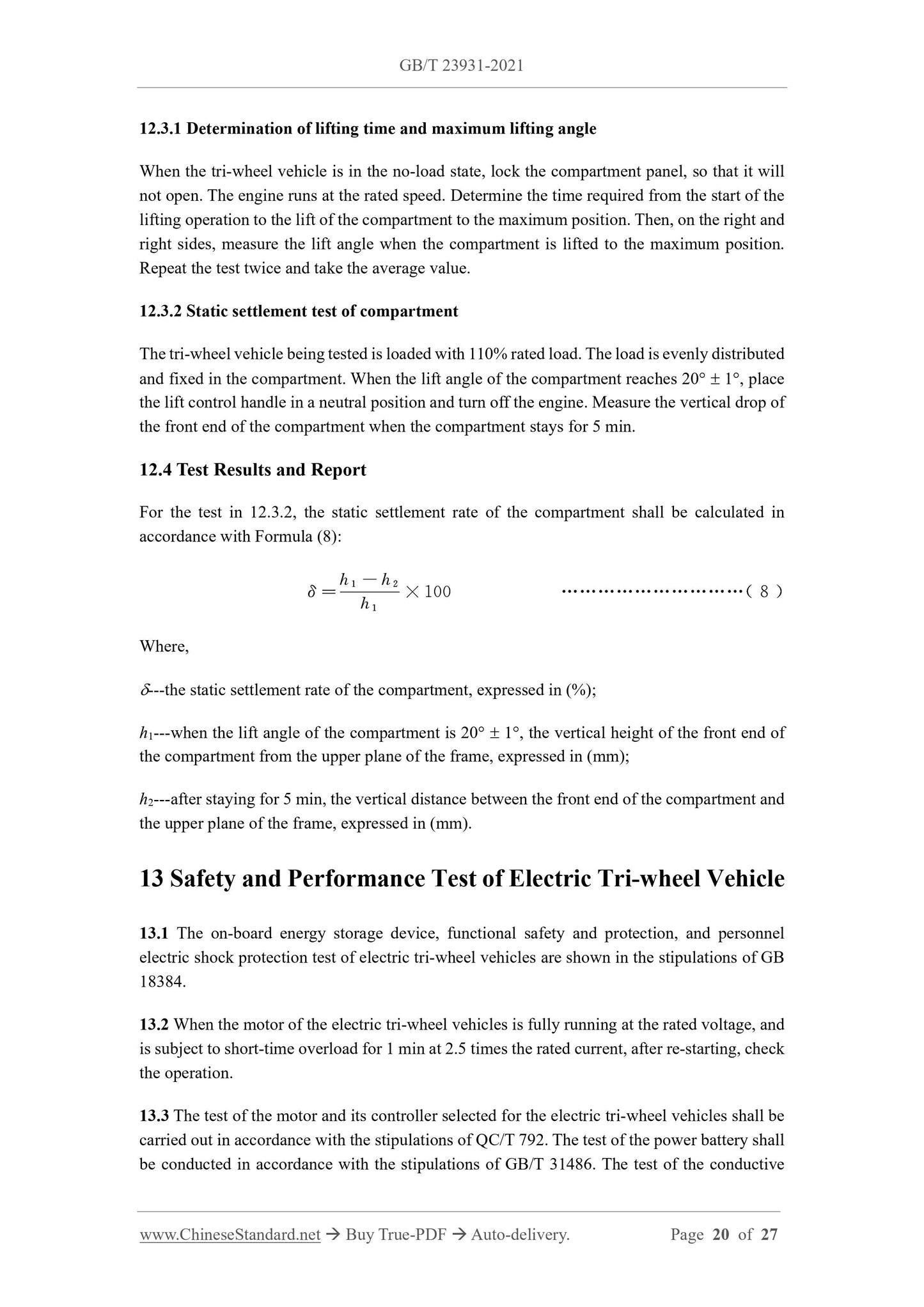
For the test in 12.3.2, the static settlement rate of the compartment shall be calculated in accordance with Formula (8):
Where,
---the static settlement rate of the compartment, expressed in (%);
h1---when the lift angle of the compartment is 20  1, the vertical height of the front end of the compartment from the upper plane of the frame, expressed in (mm);
h2---after staying for 5 min, the vertical distance between the front end of the compartment and the upper plane of the frame, expressed in (mm).
13 Safety and Performance Test of Electric Tri-wheel Vehicle
13.1 The on-board energy storage device, functional safety and protection, and personnel electric shock protection test of electric tri-wheel vehicles are shown in the stipulations of GB 18384.
13.2 When the motor of the electric tri-wheel vehicles is fully running at the rated voltage, and is subject to short-time overload for 1 min at 2.5 times the rated current, after re-starting, check the operation.
13.3 The test of the motor and its controller selected for the electric tri-wheel vehicles shall be carried out in accordance with the stipulations of QC/T 792. The test of the power battery shall be conducted in accordance with the stipulations of GB/T 31486. The test of the conductive 21 Rainfall Test of Fully Enclosed Cab
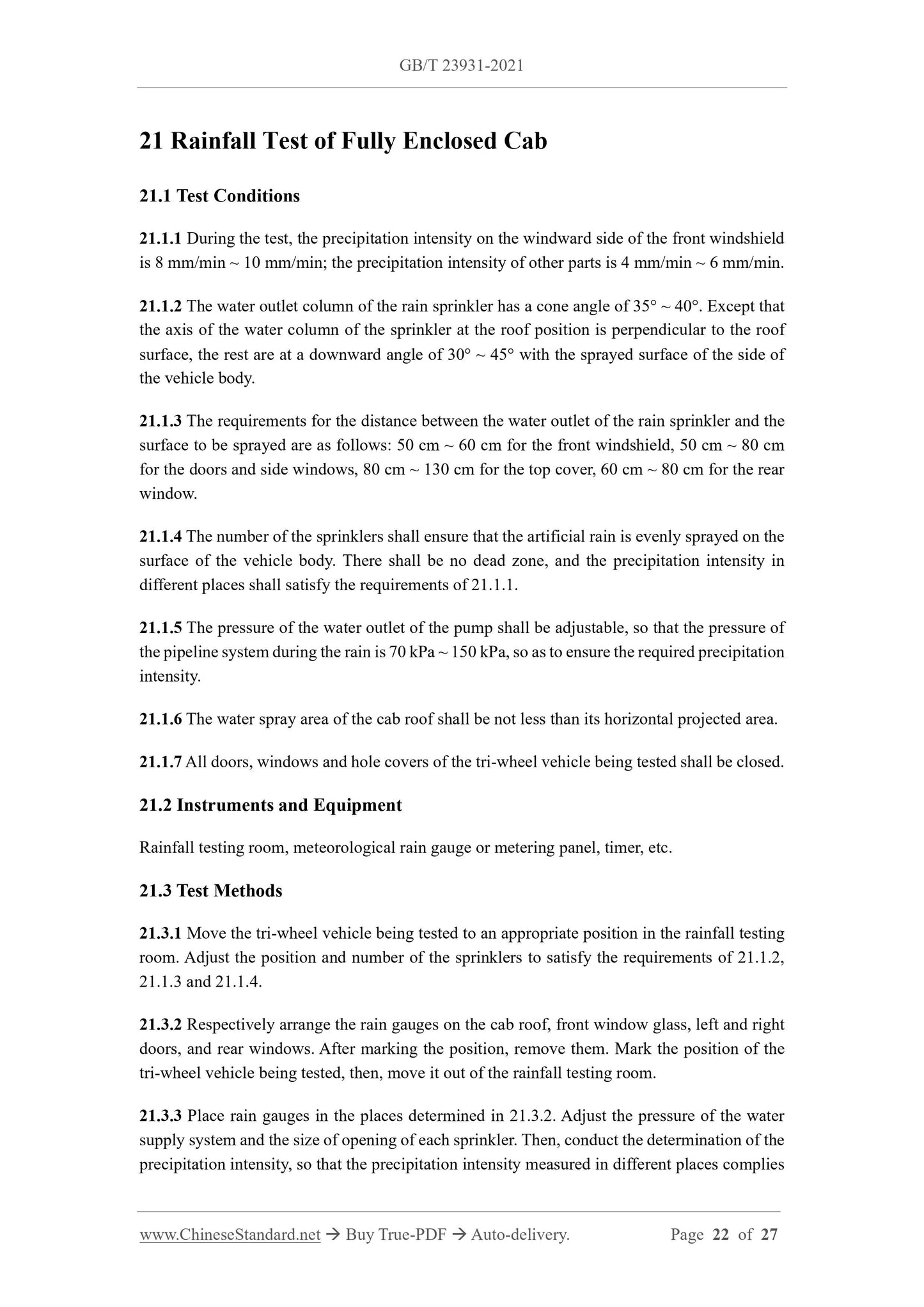
21.1 Test Conditions
21.1.1 During the test, the precipitation intensity on the windward side of the front windshield is 8 mm/min ~ 10 mm/min; the precipitation intensity of other parts is 4 mm/min ~ 6 mm/min. 21.1.2 The water outlet column of the rain sprinkler has a cone angle of 35 ~ 40. Except that the axis of the water column of the sprinkler at the roof position is perpendicular to the roof surface, the rest are at a downward angle of 30 ~ 45 with the sprayed surface of the side of the vehicle body.
21.1.3 The requirements for the distance between the water outlet of the rain sprinkler and the surface to be sprayed are as follows: 50 cm ~ 60 cm for the front windshield, 50 cm ~ 80 cm for the doors and side windows, 80 cm ~ 130 cm for the top cover, 60 cm ~ 80 cm for the rear window.
21.1.4 The number of the sprinklers shall ensure that the artificial rain is evenly sprayed on the surface of the vehicle body. There shall be no dead zone, and the precipitation intensity in different places shall satisfy the requirements of 21.1.1.
21.1.5 The pressure of the water outlet of the pump shall be adjustable, so that the pressure of the pipeline system during the rain is 70 kPa ~ 150 kPa, so as to ensure the required precipitation intensity.
21.1.6 The water spray area of the cab roof shall be not less than its horizontal projected area. 21.1.7 All doors, windows and hole covers of the tri-wheel vehicle being tested shall be closed. 21.2 Instruments and Equipment
Rainfall testing room, meteorological rain gauge or metering panel, timer, etc. 21.3 Test Methods
21.3.1 Move the tri-wheel vehicle being tested to an appropriate position in the rainfall testing room. Adjust the position and number of the sprinklers to satisfy the requirements of 21.1.2, 21.1.3 and 21.1.4.
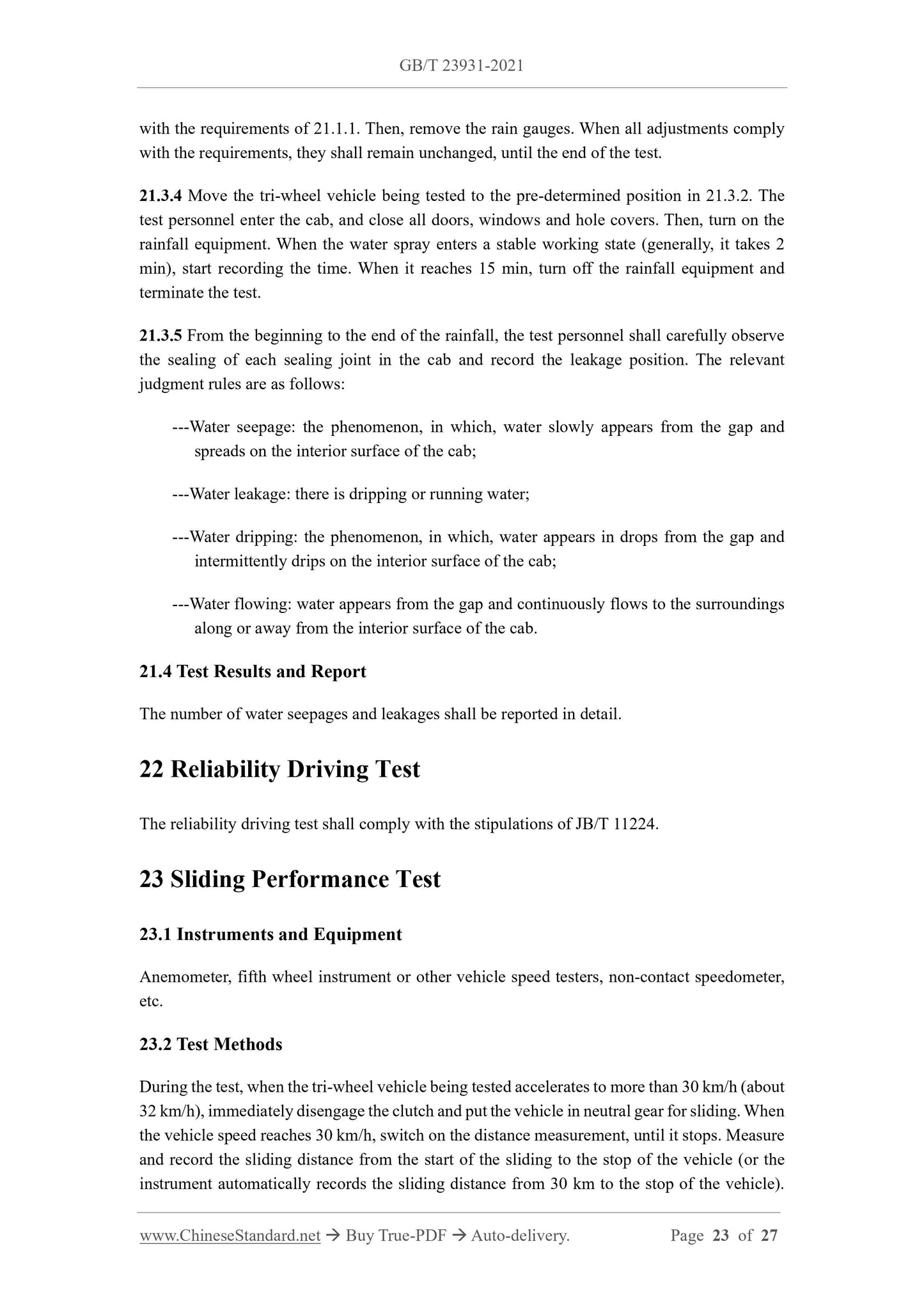
21.3.2 Respectively arrange the rain gauges on the cab roof, front window glass, left and right doors, and rear windows. After marking the position, remove them. Mark the position of the tri-wheel vehicle being tested, then, move it out of the rainfall testing room. 21.3.3 Place rain gauges in the places determined in 21.3.2. Adjust the pressure of the water supply system and the size of opening of each sprinkler. Then, conduct the determination of the precipitation intensity, so that the precipitation intensity measured in different places complies with the requirements of 21.1.1. Then, remove the rain gauges. When all adjustments comply with the requirements, they shall remain unchanged, until the end of the test. 21.3.4 Move the tri-wheel vehicle being tested to the pre-determined position in 21.3.2. The test personnel enter the cab, and close all doors, windows and hole covers. Then, turn on the rainfall equipment. When the water spray enters a stable working state (generally, it takes 2 min), start recording the time. When it reaches 15 min, turn off the rainfall equipment and terminate the test.
21.3.5 From the beginning to the end of the rainfall, the test personnel shall carefully observe the sealing of each sealing joint in the cab and record the leakage position. The relevant judgment rules are as follows:
---Water seepage: the phenomenon, in which, water slowly appears from the gap and spreads on the interior surface of the cab;
---Water leakage: there is dripping or running water;
---Water dripping: the phenomenon, in which, water appears in drops from the gap and intermittently drips on the interior surface of the cab;
---Water flowing: water a...

View full details