1
/
of
7
PayPal, credit cards. Download editable-PDF and invoice in 1 second!
GB/T 2317.3-2008 English PDF (GB/T2317.3-2008)
Regular price
$220.00 USD
Regular price
Sale price
$220.00 USD
Unit price
/
per
Shipping calculated at checkout.
Couldn't load pickup availability
Delivery: 3 seconds. Download true-PDF + Invoice.
Get Quotation: Click GB/T 2317.3-2008 (Self-service in 1-minute)
Historical versions (Master-website): GB/T 2317.3-2008
Preview True-PDF (Reload/Scroll-down if blank)
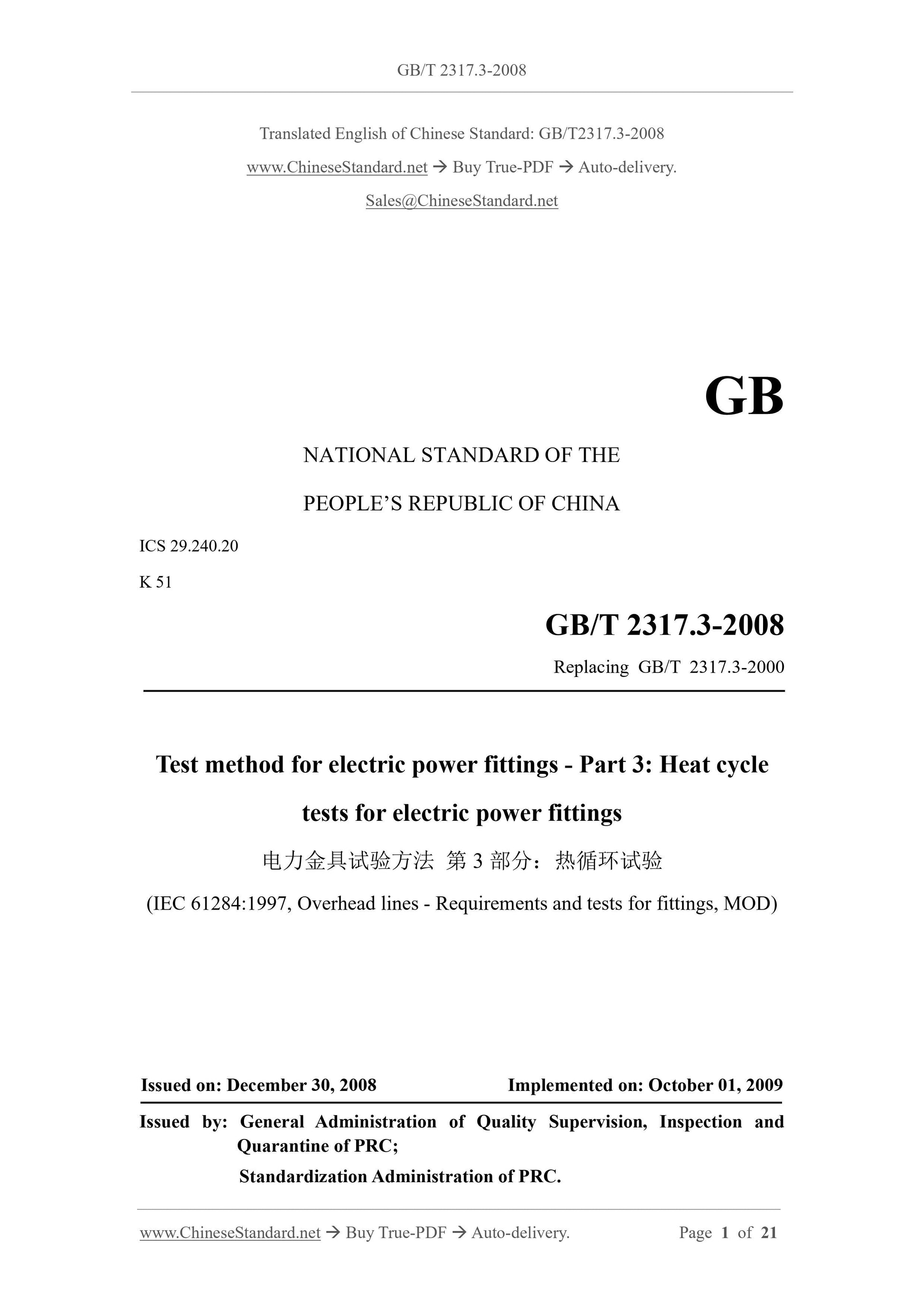
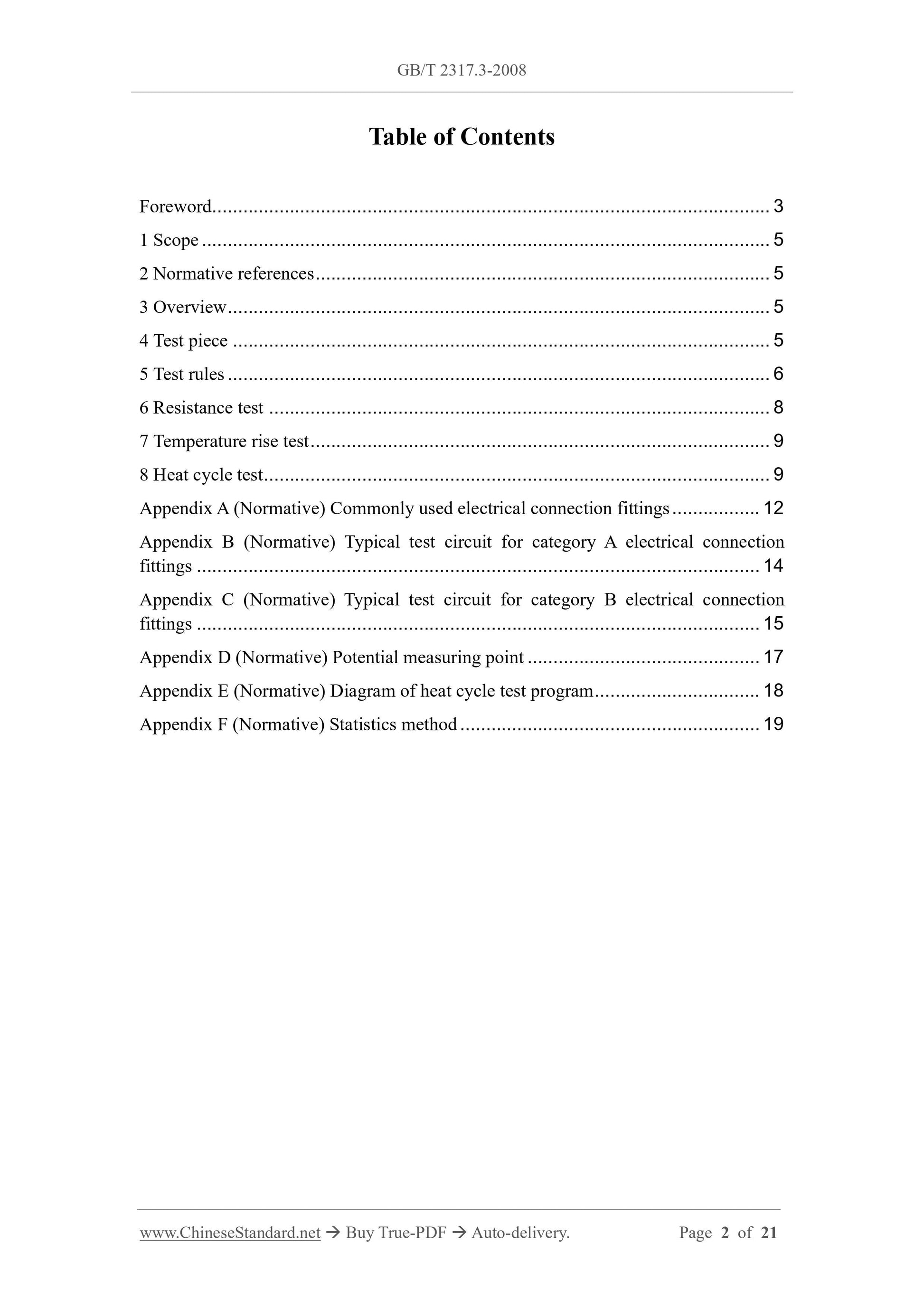
GB/T 2317.3-2008: Test method for electric power fittings -- Part 3: Heat cycle tests for electric power fittings
GB/T 2317.3-2008
Test method for electric power fittings -- Part 3.Heat cycle tests for electric power fittings
ICS 29.240.20
K51
National Standards of People's Republic of China
GB/T 2317.3-2008
Replacing GB/T 2317.3-2000
Test method for electrical fittings
Part 3.Thermal cycling test
(IEC 61284.1997, Overheadlines-
Requirements and tests for fittings, MOD)
Published on.2008-12-30
2009-10-01 Implementation
General Administration of Quality Supervision, Inspection and Quarantine of the People's Republic of China
Released by the Standardization Administration of China
foreword
GB/T 2317 "Test methods for electrical fittings" has 4 parts, which are.
GB/T 2317.1 "Test methods for electrical fittings - Part 1.Mechanical test"
GB/T 2317.2 "Test methods for electrical fittings - Part 2.Corona and radio interference test"
GB/T 2317.3 "Test methods for electrical fittings - Part 3.Thermal cycle test"
GB/T 2317.4 "Test methods for electrical fittings - Part 4.Acceptance rules"
This part is Part 3 of GB/T 2317.
This section revised and adopted the relevant content of IEC 61284.1997 "Requirements and Tests for Overhead Line Fittings". Headquarters
Compared with IEC 61284.1997, the main differences are as follows.
① The temperature rise test and resistance test are listed separately, so as to facilitate the testing and testing of products according to different requirements;
② On the basis of the relevant values of the IEC standard, the number of thermal cycles N and the temperature rise Tf are supplemented;
③ The test methods for the electrical connection fittings of class A that are subjected to tensile force and class B that are not subjected to tensile force are unified.
This Part replaces GB/T 2317.3-2000.
Compared with GB/T 2317.3-2000, this Part has the following modifications.
--- Change "General Requirements" in Chapter 3 of the original standard to "Overview", and cancel the original standard 3.2 to make the content clear and conducive to the standard's
implement;
--- The provisions of "number of test pieces" are revised to "execute according to the provisions of GB/T 2317.4.";
---In the chapter "Experimental Rules", the text of some clauses has been adjusted to make the definition of each clause clearer;
--- Newly added "Resistance Test" as Chapter 6 of the new standard;
--- A new "temperature rise test" has been added as Chapter 7 of the new standard;
---"Thermal cycle test" is Chapter 8 of the new standard, and "other conductors with higher operating temperatures such as heat-resistant wires" are added.
The test method of line matching fittings can be implemented by reference. ";
--- The formula in Appendix F has been revised.
Appendix A, Appendix B, Appendix C, Appendix D, Appendix E and Appendix F of this part are normative appendices.
This part is proposed by China Electricity Council.
This part is under the jurisdiction of the National Overhead Line Standardization Technical Committee.
The unit responsible for drafting this section. China Electric Power Research Institute.
Participated in the drafting of this section. Nanjing Line Equipment Factory.
The main drafters of this section. Bo Tong, Xu Naiguan, Dong Jizhen, Chen Ning, Liu Changqing, You Chuanyong, Wang Jingchao, Zhou Lixian.
The previous versions of the standards replaced by this part are.
--- GB/T 2317-1985, GB/T 2317.3-2000.
GB/T 2317.3-2008
Test method for electrical fittings
Part 3.Thermal cycling test
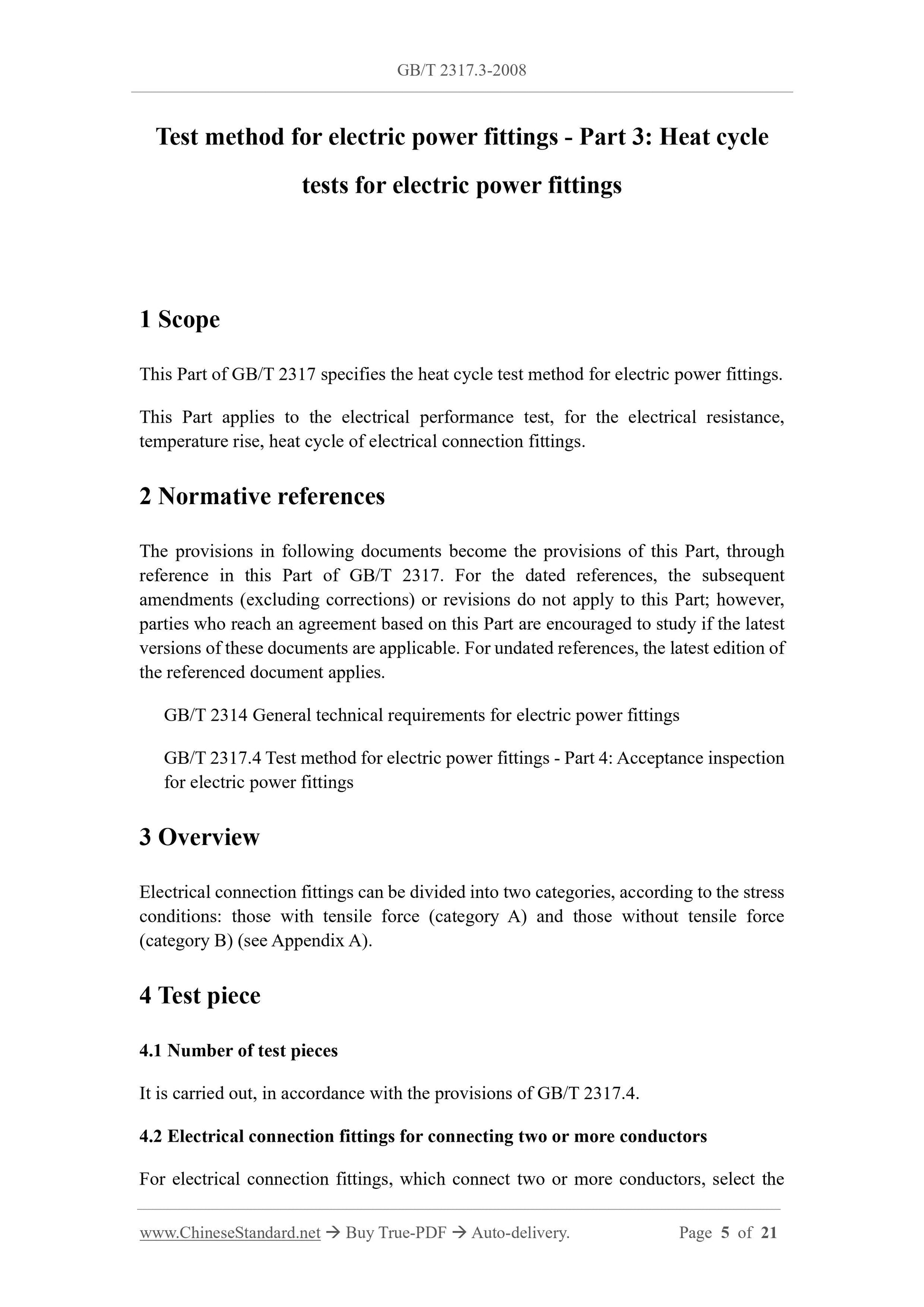
1 range
This part of GB/T 2317 specifies the thermal cycle test method for electrical fittings.
This part applies to the electrical performance test of electrical resistance, temperature rise and thermal cycle of electrical connection fittings.
2 Normative references
The terms in the following documents become the terms of this part by reference to this part of GB/T 2317.All dated citations
document, all subsequent amendments (excluding errata) or revisions do not apply to this part, however, it is encouraged to reach agreement in accordance with this part
The parties to the agreement study the availability of the latest versions of these documents. For undated references, the latest edition applies to this
part.
GB/T 2314 General technical conditions for power fittings
GB/T 2317.4 Test methods for electrical fittings - Part 4.Acceptance rules
3 Overview
The electrical connection fittings can be divided into two categories according to the stress conditions. those with tensile force (Type A) and those without tensile force (Type B) (see Appendix A).
4 Test pieces
4.1 Number of test pieces
According to the provisions of GB/T 2317.4.
4.2 Electrical connection fittings for connecting two or more wires
For electrical connection fittings connecting two or more types of conductors, select the largest and smallest conductors for testing.
4.3 Preparation
The electrical connection fittings and the contact surfaces on the wires should be treated according to the manufacturer's instructions, and then installed on the new wires without any
loose.
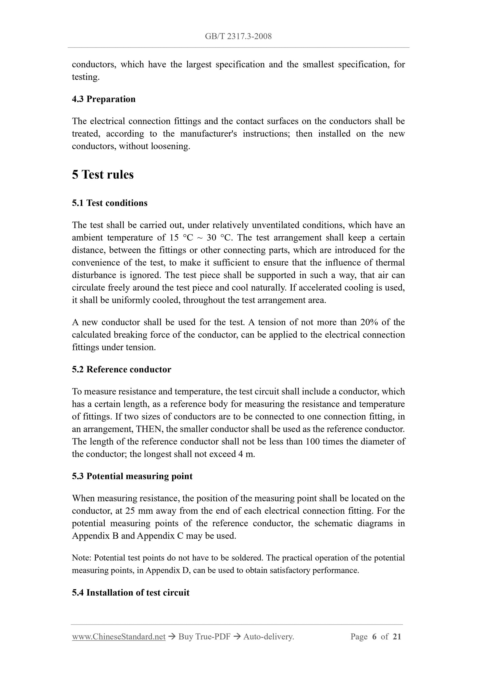
5 Test rules
5.1 Test conditions
The test should be carried out under relatively unventilated conditions at an ambient temperature of 15°C to 30°C. The test arrangement should be such that between the fittings or for the convenience of the test
A certain distance is maintained between the other connectors introduced, which is sufficient to ensure that the influence of thermal disturbance is ignored. The support method of the test piece should be empty
The gas can circulate freely around the specimen and cool naturally. If accelerated cooling is used, it shall be uniformly cooled throughout the test arrangement.
A new wire should be used for the test, and a tension of no more than 20% of the calculated breaking force of the wire can be applied to the electrical connection fittings under tension.
5.2 Reference lead
For measuring resistance and temperature, the test circuit shall include a wire with a certain length as a reference for measuring the resistance and temperature of the fittings
body. If two sizes of wire are to be connected to one splice in an arrangement, the smaller wire should be used as the reference wire. reference wire
The length of the wire shall not be less than 100 times the diameter of the wire, and the longest shall not exceed 4m.
5.3 Potential measuring point
When measuring resistance, the position of the measuring point should be located on the wire 25mm away from the end of each electrical connection fitting. For the electrical reference wire
GB/T 2317.3-2008
The location measuring points can be in the schematic form of Appendix B and Appendix C.
Note. Potential test points do not have to be soldered. The practical operation method of the potential measuring point in Appendix D can obtain satisfactory performance.
5.4 Installation of test circuit
The typical arrangement of the test circuit is shown in Appendix B and Appendix C.
5.5 Measurement method
5.5.1 Resistance measurement method
The resistance measurement of each test electrical connection fitting and reference wire shall be carried out between the potential measuring points specified in 5.3.
When measuring the resistance, the temperature of the reference wire and the temperature of the test electrical connection fittings should be read out, and the resistance value at 20°C should be obtained by the following formula.
The resistance measurement should be carried out at a stable ambient temperature between 15°C and 30°C, and the measured resistance is a DC resistance. Current introduction point distance
The distance of the electrical connection fittings shall not be less than 50 times the diameter of the wire, and shall be effectively connected to all strands of the wire.
This condition must be taken into account when blocking.
The error of the instrument used to measure the resistance is not more than 1%, or not more than 0.5μΩ.
Note. When the judging method of the statistical method in Appendix F is used, the error of the measured resistance will increase the possibility that the test piece cannot pass the test. To this end, consider
The following situations.
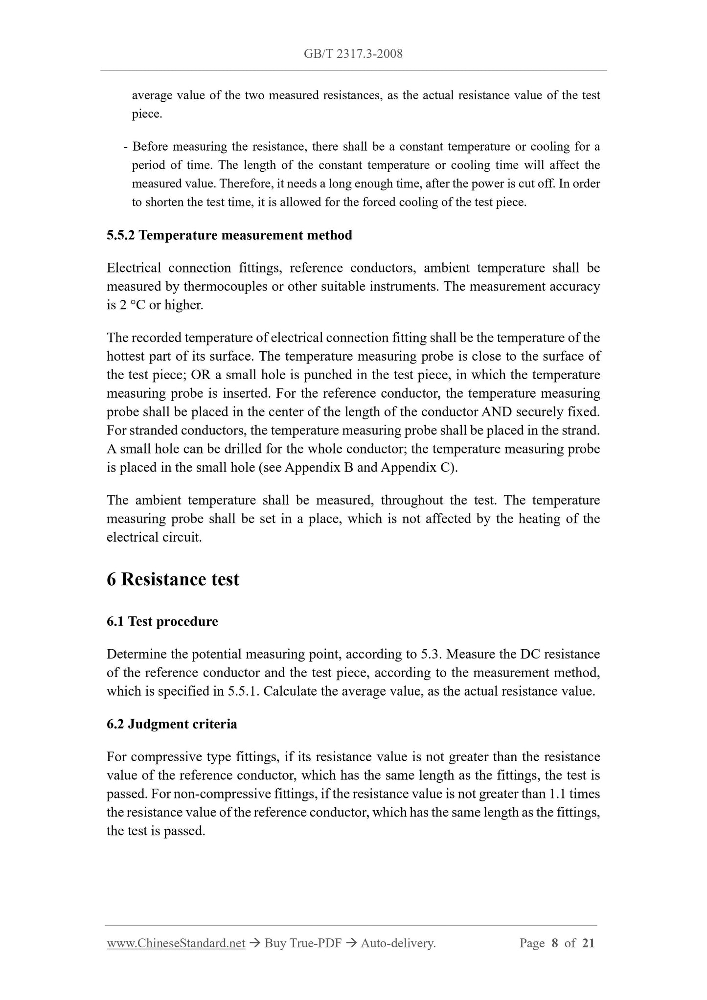
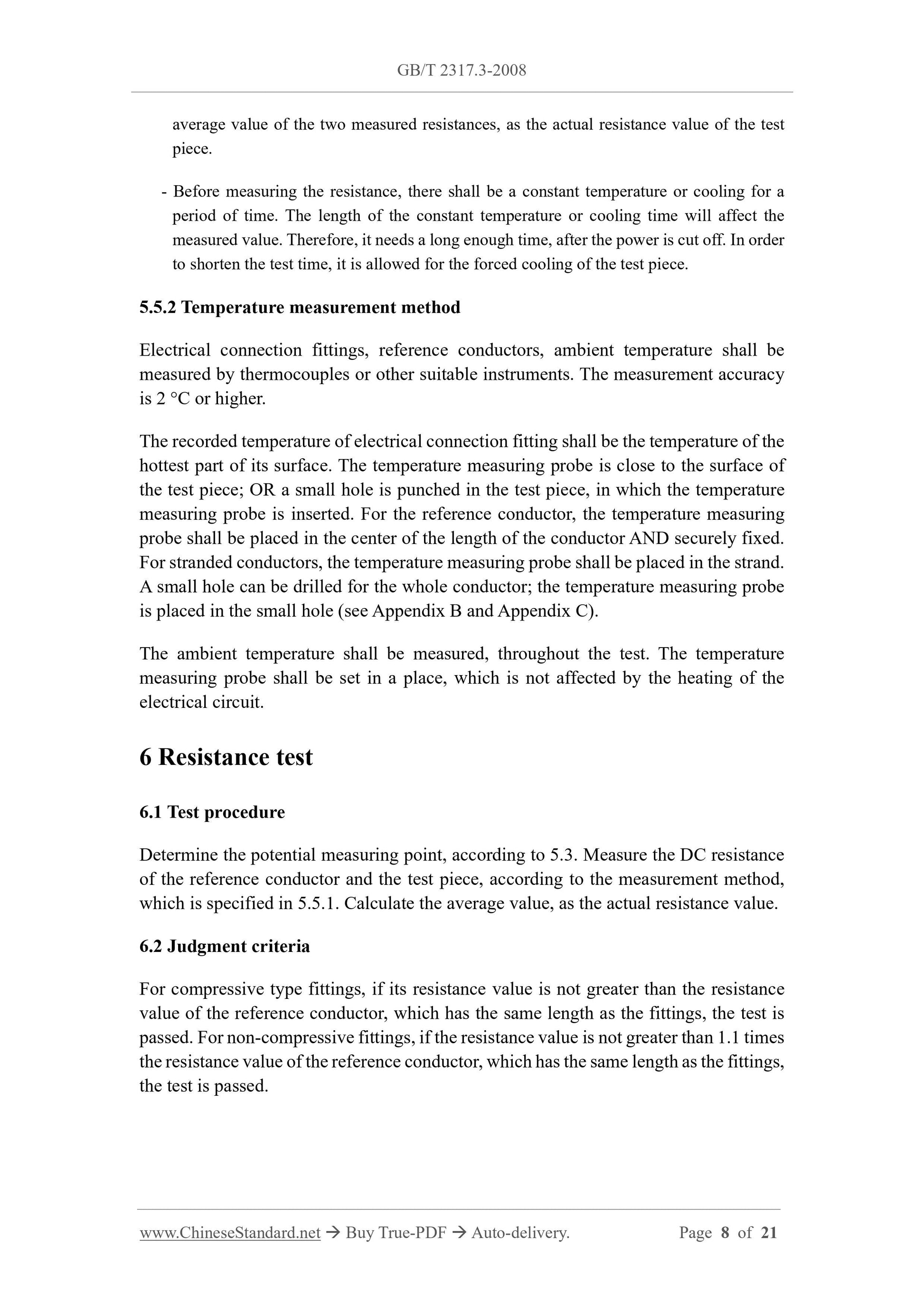
---The thermoelectric potential will affect the measurement accuracy of low resistance (about 10μΩ). As compensation, the direction of the lead current should be changed, and the average value of the two measured resistances should be taken as
is the actual resistance value of the test piece.
---Before measuring the resistance, there should be a constant temperature or cooling for a period of time. The length of the constant temperature or cooling time will affect the measured value. Therefore, it is necessary to cut off the power supply.
long enough. In order to shorten the test time, forced cooling of the test piece is allowed.
5.5.2 Temperature measurement method
Electrical connection fittings, reference wires and ambient temperature should be measured with thermocouples or other suitable instruments. The measurement accuracy is 2°C
or higher precision.
The recorded electrical connection fitting temperature shall be the temperature of the hottest part of its surface. The temperature probe is close to the surface of the test piece, or on the test piece
Punch a small hole and insert the temperature probe into the small hole. For the reference wire, the temperature probe should be placed in the center of the length of the wire and securely fixed.
For stranded conductors, the temperature probe shall be placed in the strand. For the whole conductor, a small hole can be drilled, and the temperature measuring probe can be placed in the small hole (see Appendix B
and Appendix C).
The ambient temperature shall be measured throughout the test, and the temperature probe shall be set in a place not affected by the heating of the electrical circuit.
6 Resistance test
6.1 Test procedure
Determine the potential measuring point according to the provisions of 5.3, and test the DC resistance of the reference wire and the test piece according to the measurement method specified in 5.5.1, and calculate
The average value is taken as the actual resistance value.
6.2 Judgment criteria
For compression type fittings, if its resistance value is not greater than the resistance value of the reference wire of the same length as the fittings, the test is passed. for uncompressed
If the resistance value of the fittings is not greater than 1.1 times the resistance value of the reference wire of the same length as the fittings, the test is passed.
GB/T 2317.3-2008
7 Temperature rise test
7.1 Test procedure
Pass the test current into the test loop, according to the measurement method specified in 5.5.2, within the last 15min of the constant temperature of 30min, test the parameters.
According to the temperature of the wire and the test piece. The temperature rise test shall be repeated 3 to 5 times, and the temperature rise value shall be calculated. Take the average of the test results as the test
result.
7.2 Judgment criteria
If the temperature rise of the test piece is not greater than that of the reference wire, the test is passed.
8 Thermal cycle test
8.1 General
The thermal cycle test includes N times of current-carrying cycles, and the number of cycles and temperature rise are performed according to Table 1.
Each thermal cycle consists of an energized heating process of the test loop followed by a cooling process of cutting off the current. Thermal cycle test
It should be done with alternating current.
For heat-resistant conductors and other conductors with higher operating temperature, the test method of supporting hardware can be implemented by reference, or negotiated by both the supplier and the buyer.
Sure.
8.2 Test procedure
a) Prepare the test piece according to the requirements of 4.3.4 test pieces are arranged in the test circuit.
resistance and the resistance of the reference wire. Calculate or measure the resistance value on the equivalent length of the reference wire according to the length of the test piece;
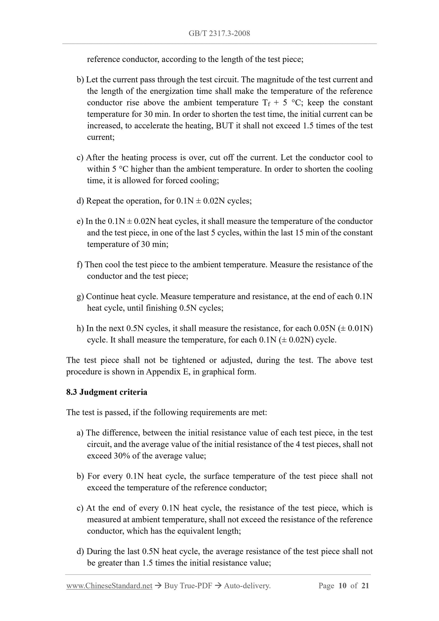
b) Let the current pass through the test circuit, the size of the test current and the length of the energization time should make the temperature of the reference wire rise to the ambient temperature
Above Tf+5℃, constant temperature for 30min. In order to shorten the test time, the initial current can be increased to accelerate the heating, but it shall not exceed the test time.
1.5 times the current;
c) When the heating process is over, cut off the current and let the wire cool to within 5°C higher than the ambient temperature. In order to shorten the cooling time, forced
cool down;
d) Repeat the operation for 0.1N±0.02N cycles;
e) In 0.1N±0.02N thermal cycles, in one of the last 5 cycles, within the last 15min of the constant temperature of 30min,
Measure the temperature of the wire and the test piece;
f) Then cool the temperature of the test piece to the ambient temperature, and measure the resistance of the wire and the test piece;
g) Continue the thermal cycle, measure the temperature and resistance at the end of each 0.1N thermal cycle, until the 0.5N cycle is completed;
h) In the following 0.5N cycles, the resistance should be measured every 0.05N (±0.01N) cycles, each 0.1N (±0.02N)
The second cycle is to measure the temperature.
The test piece shall not be tightened or adjusted during the test. The above test procedure is shown in Appendix E in graphical form.
8.3 Judgment criteria
The test is passed if the following requirements are met.
a) The difference between the initial resistance value of each test piece in the test loop and the average value of the initial resistance of the four test pieces should not exceed the average value.
30% of the
GB/T 2317.3-2008
b) For every 0.1N thermal cycle, the surface temperature of the test piece shall not exceed the temperature of the reference wire;
c) At the end of every 0.1N thermal cycle, the resistance of the test piece measured at ambient temperature shall not exceed the equivalent length resistance of the reference wire;
d) During the last 0.5N thermal cycles, the average resistance of the test piece shall not be greater than 1.5 times the initial resistance value;
e) The graph of the relationship between resistance and thermal cycling shall indicate a reasonable probabili...
Share