Skip to product information
1 of 8

www.ChineseStandard.us -- Field Test Asia Pte. Ltd.

GB/T 22311-2023 English PDF (GB/T22311-2023)

GB/T 22311-2023 English PDF (GB/T22311-2023)

Regular price $230.00
Regular price Sale price $230.00
Sale Sold out
Shipping calculated at checkout.
GB/T 22311-2023: Road vehicles - Brake linings - Compressive strain test method
Delivery: 9 seconds. Download (& Email) true-PDF + Invoice.
Get Quotation: Click GB/T 22311-2023 (Self-service in 1-minute)
Historical versions (Master-website): GB/T 22311-2023
Preview True-PDF (Reload/Scroll-down if blank)

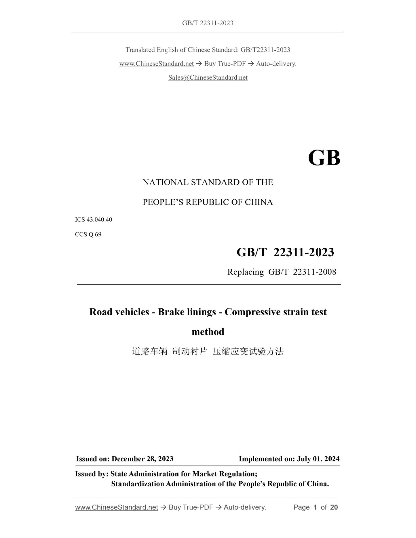
GB/T 22311-2023
GB
NATIONAL STANDARD OF THE
PEOPLE’S REPUBLIC OF CHINA
ICS 43.040.40
CCS Q 69
Replacing GB/T 22311-2008
Road vehicles - Brake linings - Compressive strain test
method
ISSUED ON: DECEMBER 28, 2023
IMPLEMENTED ON: JULY 01, 2024
Issued by: State Administration for Market Regulation;
Standardization Administration of the People’s Republic of China.
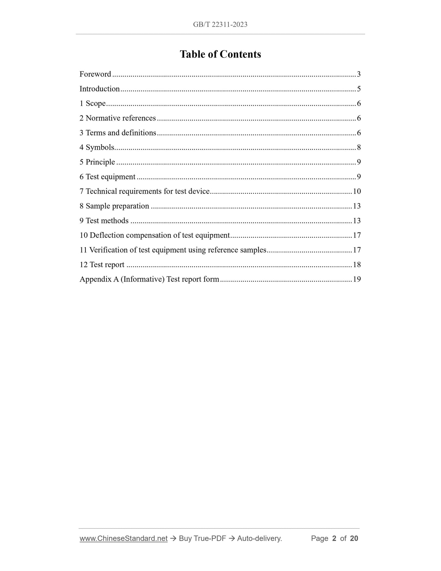
Table of Contents
Foreword ... 3
Introduction ... 5
1 Scope ... 6
2 Normative references ... 6
3 Terms and definitions ... 6
4 Symbols ... 8
5 Principle ... 9
6 Test equipment ... 9
7 Technical requirements for test device ... 10
8 Sample preparation ... 13
9 Test methods ... 13
10 Deflection compensation of test equipment ... 17
11 Verification of test equipment using reference samples ... 17
12 Test report ... 18
Appendix A (Informative) Test report form ... 19
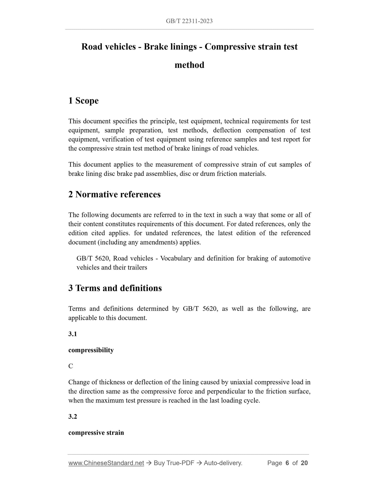
Road vehicles - Brake linings - Compressive strain test
method
1 Scope
This document specifies the principle, test equipment, technical requirements for test
equipment, sample preparation, test methods, deflection compensation of test
equipment, verification of test equipment using reference samples and test report for
the compressive strain test method of brake linings of road vehicles.
This document applies to the measurement of compressive strain of cut samples of
brake lining disc brake pad assemblies, disc or drum friction materials.
2 Normative references
The following documents are referred to in the text in such a way that some or all of
their content constitutes requirements of this document. For dated references, only the
edition cited applies. for undated references, the latest edition of the referenced
document (including any amendments) applies.
GB/T 5620, Road vehicles - Vocabulary and definition for braking of automotive
vehicles and their trailers
3 Terms and definitions
Terms and definitions determined by GB/T 5620, as well as the following, are
applicable to this document.
3.1
compressibility
Change of thickness or deflection of the lining caused by uniaxial compressive load in
the direction same as the compressive force and perpendicular to the friction surface,
when the maximum test pressure is reached in the last loading cycle.
3.2
compressive strain
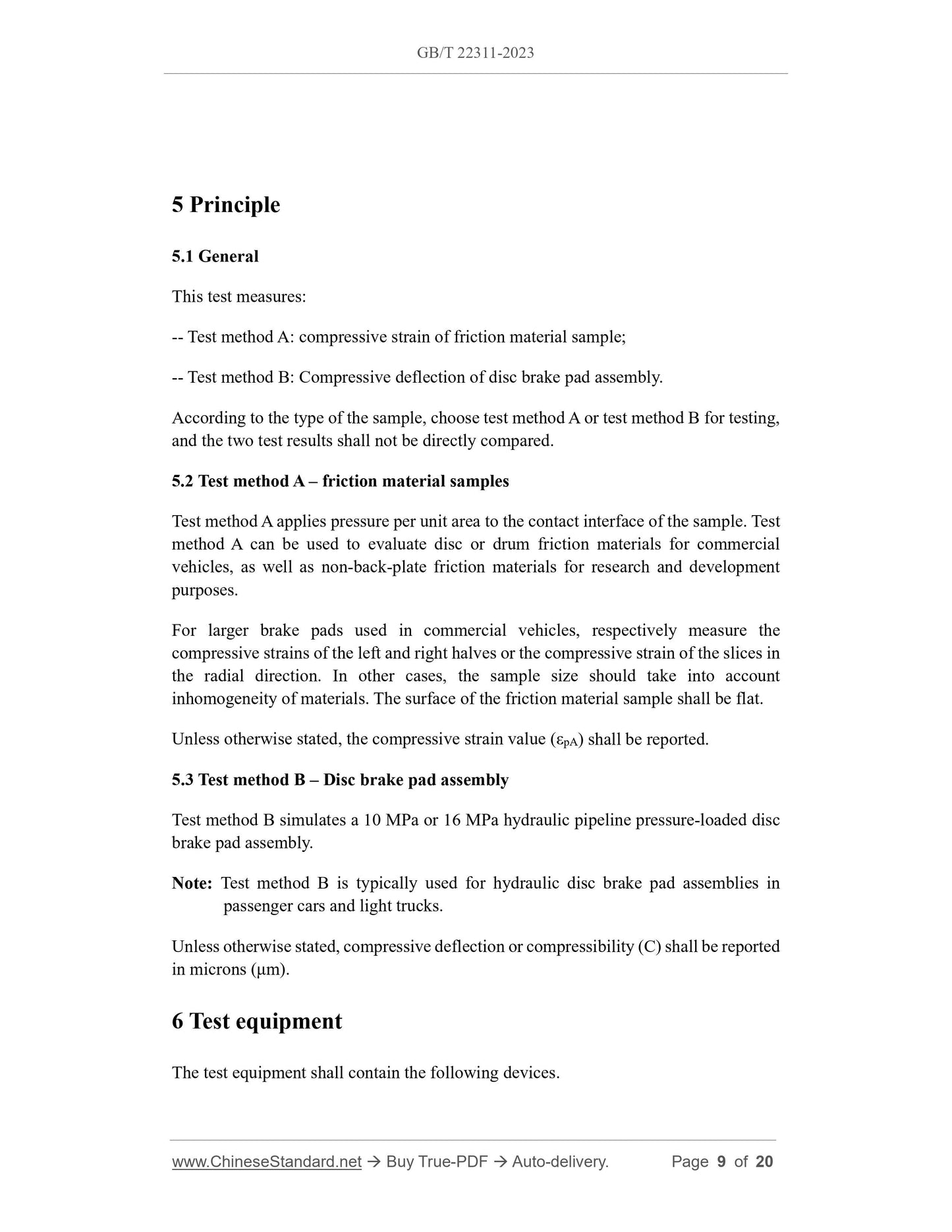
5 Principle
5.1 General
This test measures:
-- Test method A: compressive strain of friction material sample;
-- Test method B: Compressive deflection of disc brake pad assembly.
According to the type of the sample, choose test method A or test method B for testing,
and the two test results shall not be directly compared.
5.2 Test method A – friction material samples
Test method A applies pressure per unit area to the contact interface of the sample. Test
method A can be used to evaluate disc or drum friction materials for commercial
vehicles, as well as non-back-plate friction materials for research and development
purposes.
For larger brake pads used in commercial vehicles, respectively measure the
compressive strains of the left and right halves or the compressive strain of the slices in
the radial direction. In other cases, the sample size should take into account
inhomogeneity of materials. The surface of the friction material sample shall be flat.
Unless otherwise stated, the compressive strain value (εpA) shall be reported.
5.3 Test method B – Disc brake pad assembly
Test method B simulates a 10 MPa or 16 MPa hydraulic pipeline pressure-loaded disc
brake pad assembly.
Note: Test method B is typically used for hydraulic disc brake pad assemblies in
passenger cars and light trucks.
Unless otherwise stated, compressive deflection or compressibility (C) shall be reported
in microns (μm).
6 Test equipment
The test equipment shall contain the following devices.
a) Compressibility test bench or uniaxial material test load frame: Providing
uniform load on the surface of the sample.
b) Loading cylinder for simulation: Including loading indenter for test method A
(where the surface shall be larger than the contact surface of the sample) and
caliper piston device for test method B.
c) Pressure plate.
d) Devices for applying pressure: Its accuracy is 1% of the full scale of the
equipment.
e) Deflection measuring device: Measuring the deflection of the sample as it
changes with time; its accuracy is 0.001 mm. It is placed on the loading cylinder
or pressure plate, with the center line close to the loading indenter.
f) Recording device or computer: It is used to record the changes in load, pressure,
displacement and temperature over time.
g) Heating device: Used to heat the pressure plate to the specified temperature.
h) Thermocouple (recommended diameter 1.5 mm): It is used to measure the
temperature of the back plate. The thermocouple is located close to the center
line of the back plane and embedded 3 mm below the surface of the back plate.
i) Thermocouple or other device for measuring the sample temperature.
j) Micrometer for measuring the sample thickness.
7 Technical requirements for test device
7.1 Loading
7.1.1 Test method A
Table 2 gives the maximum pressure and loading rate on the contact surface. When
determining the actual contact area and contact surface pressure of the sample, all
grooves, chamfers and holes shall be removed.
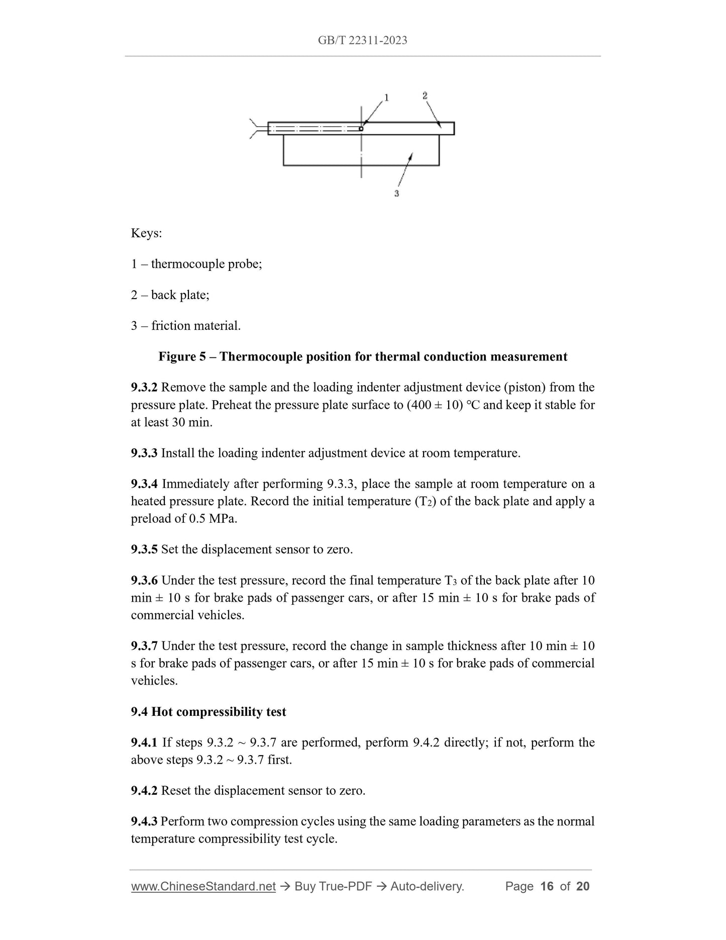
Keys:
1 – thermocouple probe;
2 – back plate;
3 – friction material.
Figure 5 – Thermocouple position for thermal conduction measurement
9.3.2 Remove the sample and the loading indenter adjustment device (piston) from the
pressure plate. Preheat the pressure plate surface to (400 ± 10) ℃ and keep it stable for
at least 30 min.
9.3.3 Install the loading indenter adjustment device at room temperature.
9.3.4 Immediately after performing 9.3.3, place the sample at room temperature on a
heated pressure plate. Record the initial temperature (T2) of the back plate and apply a
preload of 0.5 MPa.
9.3.5 Set the displacement sensor to zero.
9.3.6 Under the test pressure, record the final temperature T3 of the back plate after 10
min ± 10 s for brake pads of passenger cars, or after 15 min ± 10 s for brake pads of
commercial vehicles.
9.3.7 Under the test pressure, record the change in sample thickness after 10 min ± 10
s for brake pads of passenger cars, or after 15 min ± 10 s for brake pads of commercial
vehicles.
9.4 Hot compressibility test
9.4.1 If steps 9.3.2 ~ 9.3.7 are performed, perform 9.4.2 directly; if not, perform the
above steps 9.3.2 ~ 9.3.7 first.
9.4.2 Reset the displacement sensor to zero.
9.4.3 Perform two compression cycles using the same loading parameters as the normal
temperature compressibility test cycle.
9.4.4 Remove the sample from the test equipment and cool it to room temperature.
9.4.5 Measure the thickness of the pad at the position shown in Figure 3 and report the
thermal growth (dG) of the sample as needed.
10 Deflection compensation of test equipment
During the friction material compressibility test, the test equipment itself will change.
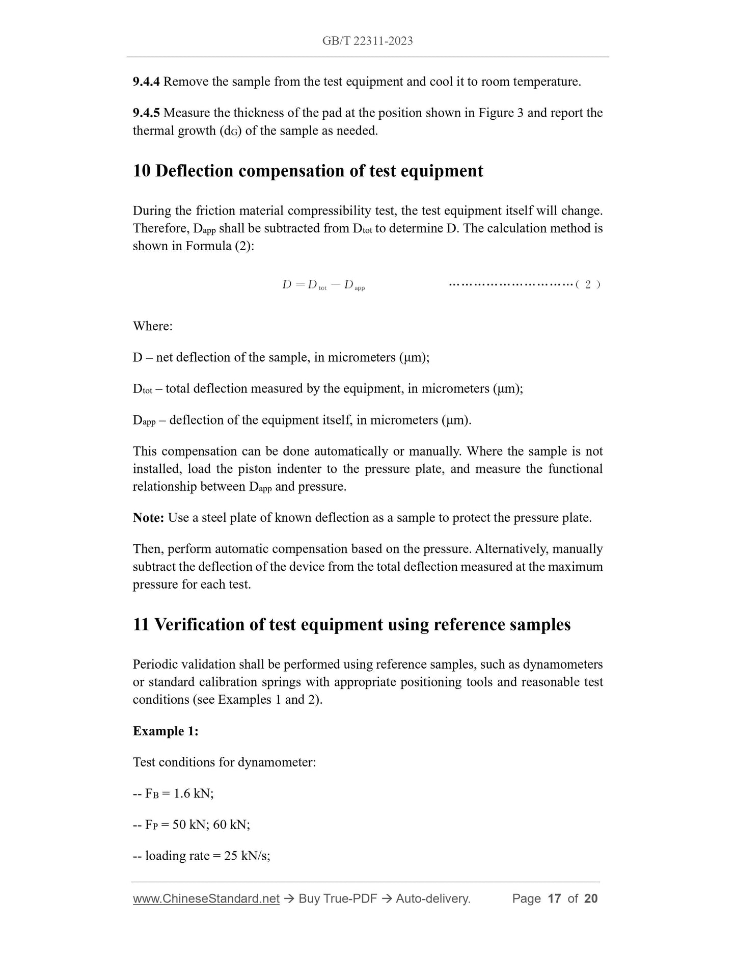
Therefore, Dapp shall be subtracted from Dtot to determine D. The calculation method is
shown in Formula (2):
Where:
D – net deflection of the sample, in micrometers (μm);
Dtot – total deflection measured by the equipment, in micrometers (μm);
Dapp – deflection of the equipment itself, in micrometers (μm).
This compensation can be done automatically or manually. Where the sample is not
installed, load the piston indenter to the pressure plate, and measure the functional
relationship between Dapp and pressure.
Note: Use a steel plate of known deflection as a sample to protect the pressure plate.
Then, perform automatic compensation based on the pressure. Alternatively, manually
subtract the deflection of the device from the total deflection measured at the maximum
pressure for each test.
11 Verification of test equipment using reference samples
Periodic validation shall be performed using reference samples, such as dynamometers
or standard calibration springs with appropriate positioning tools and reasonable test
conditions (see Examples 1 and 2).
Example 1:
Test conditions for dynamometer:
-- FB = 1.6 kN;
-- FP = 50 kN; 60 kN;
-- loading rate = 25 kN/s;
-- 2 cycles.
Example 2:
Test conditions for standard calibration spring:
-- FB = 3.0 kN;
-- FP = 59.5 kN;
-- loading rate = 35 kN/s;
-- 3 cycles.
If the difference between the reference sample and its expected value is greater than 5
μm, check the accuracy of the dynamometer, the precision of the displacement sensor
and the flatness of the test pressure plate.
12 Test report
See Appendix A for the test report form. Test reports in other formats shall at least
contain the following information:
a) Manufacturer and brake lining batch number;
b) Type of sample and additional coatings, silencers, etc.;
c) Sample size (pad area);
d) Number of samples;
e) Thickness of the assembly, accurate to 0.1 mm, thickness of the friction material;
f) Piston size, inner diameter and outer diameter (for discs);
g) If it deviates from the center line position, record the position of the piston
deviating from the pad;
h) Test method (A or B) used;
i) Average compressibility or compressive strain of the sample at room temperature;
j) Average hot compressibility or compressive strain of the sample;
k) Room temperature and relative humidity (if required).
GB/T 22311-2023
GB
NATIONAL STANDARD OF THE
PEOPLE’S REPUBLIC OF CHINA
ICS 43.040.40
CCS Q 69
Replacing GB/T 22311-2008
Road vehicles - Brake linings - Compressive strain test
method
ISSUED ON: DECEMBER 28, 2023
IMPLEMENTED ON: JULY 01, 2024
Issued by: State Administration for Market Regulation;
Standardization Administration of the People’s Republic of China.
Table of Contents
Foreword ... 3
Introduction ... 5
1 Scope ... 6
2 Normative references ... 6
3 Terms and definitions ... 6
4 Symbols ... 8
5 Principle ... 9
6 Test equipment ... 9
7 Technical requirements for test device ... 10
8 Sample preparation ... 13
9 Test methods ... 13
10 Deflection compensation of test equipment ... 17
11 Verification of test equipment using reference samples ... 17
12 Test report ... 18
Appendix A (Informative) Test report form ... 19
Road vehicles - Brake linings - Compressive strain test
method
1 Scope
This document specifies the principle, test equipment, technical requirements for test
equipment, sample preparation, test methods, deflection compensation of test
equipment, verification of test equipment using reference samples and test report for
the compressive strain test method of brake linings of road vehicles.
This document applies to the measurement of compressive strain of cut samples of
brake lining disc brake pad assemblies, disc or drum friction materials.
2 Normative references
The following documents are referred to in the text in such a way that some or all of
their content constitutes requirements of this document. For dated references, only the
edition cited applies. for undated references, the latest edition of the referenced
document (including any amendments) applies.
GB/T 5620, Road vehicles - Vocabulary and definition for braking of automotive
vehicles and their trailers
3 Terms and definitions
Terms and definitions determined by GB/T 5620, as well as the following, are
applicable to this document.
3.1
compressibility
Change of thickness or deflection of the lining caused by uniaxial compressive load in
the direction same as the compressive force and perpendicular to the friction surface,
when the maximum test pressure is reached in the last loading cycle.
3.2
compressive strain
5 Principle
5.1 General
This test measures:
-- Test method A: compressive strain of friction material sample;
-- Test method B: Compressive deflection of disc brake pad assembly.
According to the type of the sample, choose test method A or test method B for testing,
and the two test results shall not be directly compared.
5.2 Test method A – friction material samples
Test method A applies pressure per unit area to the contact interface of the sample. Test
method A can be used to evaluate disc or drum friction materials for commercial
vehicles, as well as non-back-plate friction materials for research and development
purposes.
For larger brake pads used in commercial vehicles, respectively measure the
compressive strains of the left and right halves or the compressive strain of the slices in
the radial direction. In other cases, the sample size should take into account
inhomogeneity of materials. The surface of the friction material sample shall be flat.
Unless otherwise stated, the compressive strain value (εpA) shall be reported.
5.3 Test method B – Disc brake pad assembly
Test method B simulates a 10 MPa or 16 MPa hydraulic pipeline pressure-loaded disc
brake pad assembly.
Note: Test method B is typically used for hydraulic disc brake pad assemblies in
passenger cars and light trucks.
Unless otherwise stated, compressive deflection or compressibility (C) shall be reported
in microns (μm).
6 Test equipment
The test equipment shall contain the following devices.
a) Compressibility test bench or uniaxial material test load frame: Providing
uniform load on the surface of the sample.
b) Loading cylinder for simulation: Including loading indenter for test method A
(where the surface shall be larger than the contact surface of the sample) and
caliper piston device for test method B.
c) Pressure plate.
d) Devices for applying pressure: Its accuracy is 1% of the full scale of the
equipment.
e) Deflection measuring device: Measuring the deflection of the sample as it
changes with time; its accuracy is 0.001 mm. It is placed on the loading cylinder
or pressure plate, with the center line close to the loading indenter.
f) Recording device or comput...
View full details