1
/
of
10
www.ChineseStandard.us -- Field Test Asia Pte. Ltd.
GB/T 21437.3-2021 English PDF (GB/T21437.3-2021)
Regular price
$365.00
Regular price
Sale price
$365.00
Unit price
/
per
Shipping calculated at checkout.
Couldn't load pickup availability
GB/T 21437.3-2021: Road vehicles - Test method of electrical disturbances from conduction and coupling - Part 3: Electrical transient transmission by capacitive and inductive coupling via lines other than supply lines
Delivery: 9 seconds. Download (& Email) true-PDF + Invoice.
Get Quotation: Click GB/T 21437.3-2021 (Self-service in 1-minute)
Historical versions (Master-website): GB/T 21437.3-2021
Preview True-PDF (Reload/Scroll-down if blank)
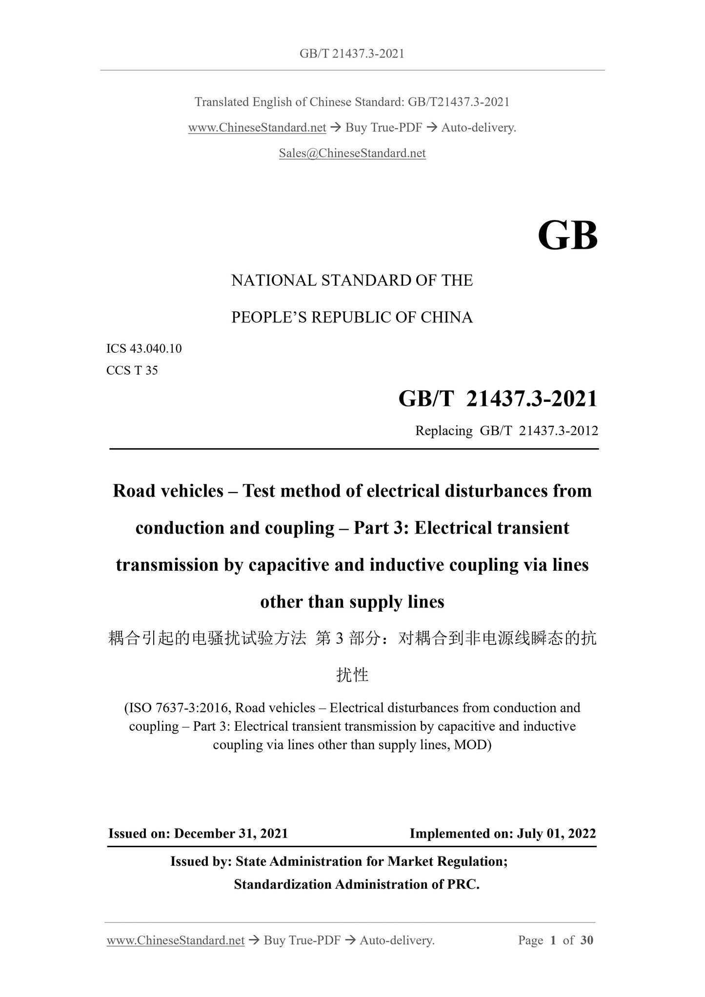
GB/T 21437.3-2021
NATIONAL STANDARD OF THE
PEOPLE’S REPUBLIC OF CHINA
ICS 43.040.10
CCS T 35
Replacing GB/T 21437.3-2012
Road vehicles – Test method of electrical disturbances from
conduction and coupling – Part 3: Electrical transient
transmission by capacitive and inductive coupling via lines
other than supply lines
扰性
(ISO 7637-3:2016, Road vehicles – Electrical disturbances from conduction and
coupling – Part 3: Electrical transient transmission by capacitive and inductive
coupling via lines other than supply lines, MOD)
ISSUED ON: DECEMBER 31, 2021
IMPLEMENTED ON: JULY 01, 2022
Issued by: State Administration for Market Regulation;
Standardization Administration of PRC.
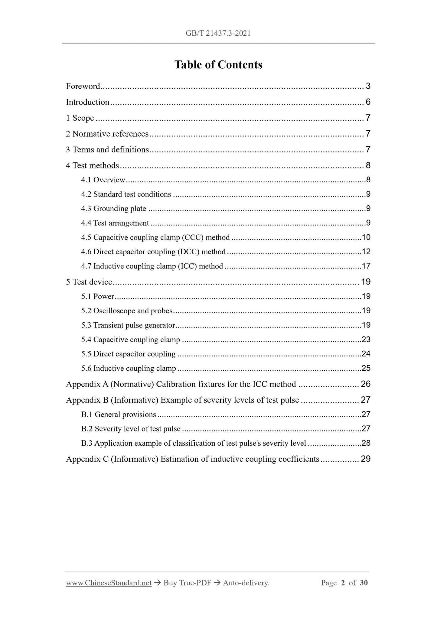
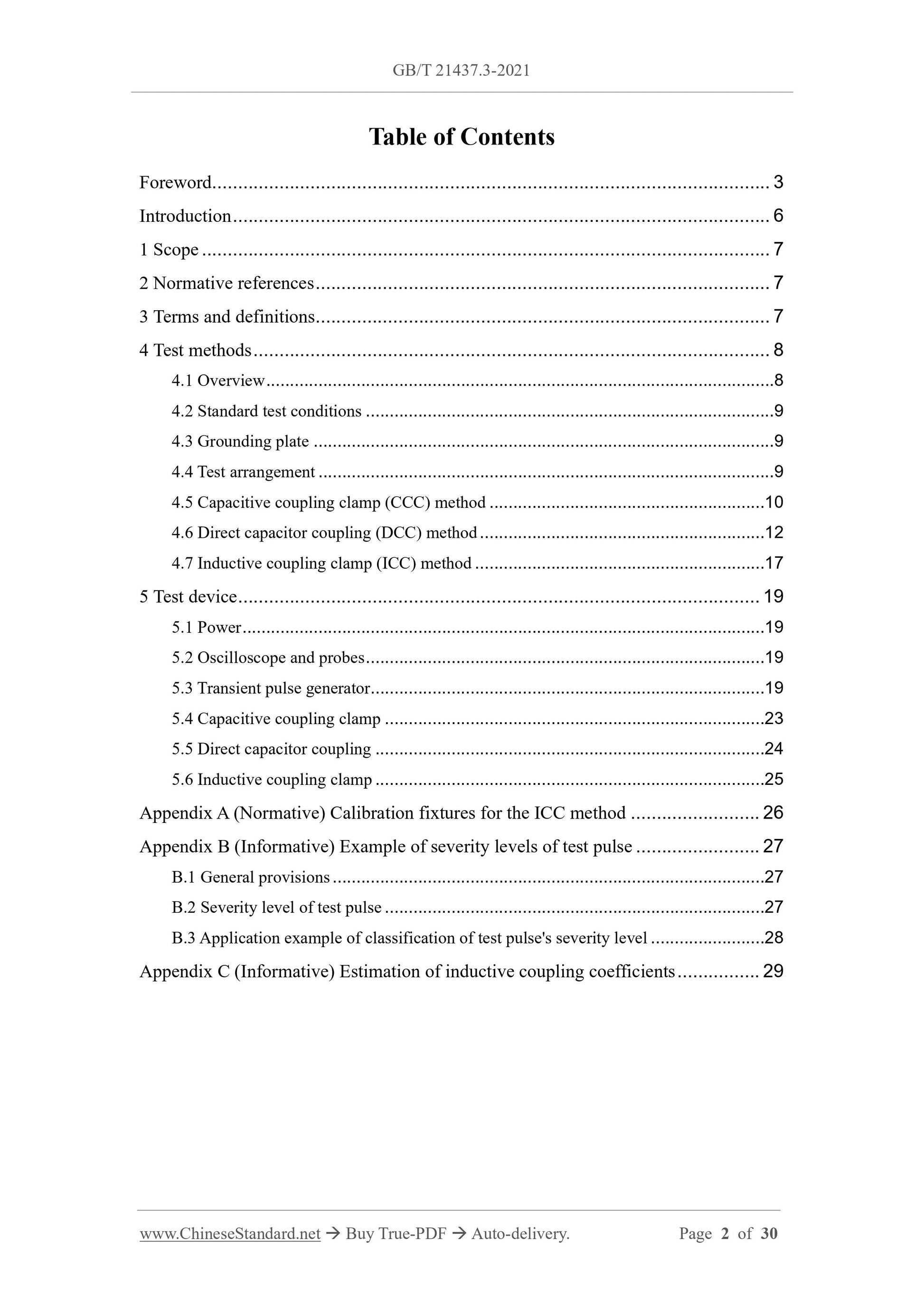
Table of Contents
Foreword ... 3
Introduction ... 6
1 Scope ... 7
2 Normative references ... 7
3 Terms and definitions... 7
4 Test methods ... 8
4.1 Overview ... 8
4.2 Standard test conditions ... 9
4.3 Grounding plate ... 9
4.4 Test arrangement ... 9
4.5 Capacitive coupling clamp (CCC) method ... 10
4.6 Direct capacitor coupling (DCC) method ... 12
4.7 Inductive coupling clamp (ICC) method ... 17
5 Test device ... 19
5.1 Power ... 19
5.2 Oscilloscope and probes ... 19
5.3 Transient pulse generator ... 19
5.4 Capacitive coupling clamp ... 23
5.5 Direct capacitor coupling ... 24
5.6 Inductive coupling clamp ... 25
Appendix A (Normative) Calibration fixtures for the ICC method ... 26
Appendix B (Informative) Example of severity levels of test pulse ... 27
B.1 General provisions ... 27
B.2 Severity level of test pulse ... 27
B.3 Application example of classification of test pulse's severity level ... 28
Appendix C (Informative) Estimation of inductive coupling coefficients ... 29
Road vehicles - Test method of electrical disturbances from
conduction and coupling - Part 3: Electrical transient
transmission by capacitive and inductive coupling via lines
other than supply lines
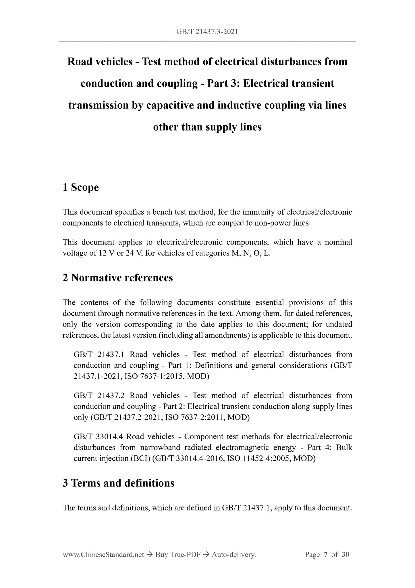
1 Scope
This document specifies a bench test method, for the immunity of electrical/electronic
components to electrical transients, which are coupled to non-power lines.
This document applies to electrical/electronic components, which have a nominal
voltage of 12 V or 24 V, for vehicles of categories M, N, O, L.
2 Normative references
The contents of the following documents constitute essential provisions of this
document through normative references in the text. Among them, for dated references,
only the version corresponding to the date applies to this document; for undated
references, the latest version (including all amendments) is applicable to this document.
GB/T 21437.1 Road vehicles - Test method of electrical disturbances from
conduction and coupling - Part 1: Definitions and general considerations (GB/T
21437.1-2021, ISO 7637-1:2015, MOD)
GB/T 21437.2 Road vehicles - Test method of electrical disturbances from
conduction and coupling - Part 2: Electrical transient conduction along supply lines
only (GB/T 21437.2-2021, ISO 7637-2:2011, MOD)
GB/T 33014.4 Road vehicles - Component test methods for electrical/electronic
disturbances from narrowband radiated electromagnetic energy - Part 4: Bulk
current injection (BCI) (GB/T 33014.4-2016, ISO 11452-4:2005, MOD)
3 Terms and definitions
The terms and definitions, which are defined in GB/T 21437.1, apply to this document.
4 Test methods
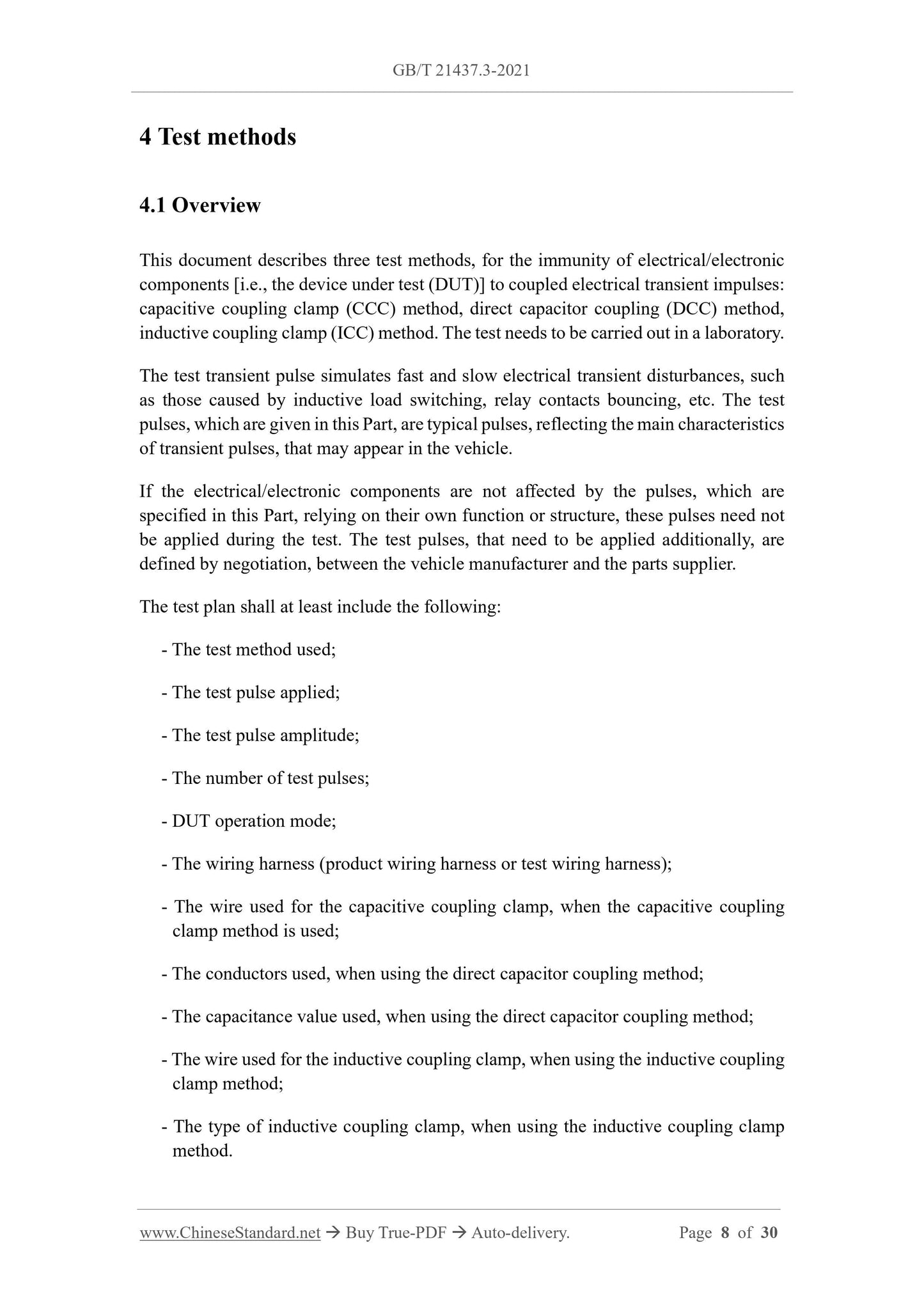
4.1 Overview
This document describes three test methods, for the immunity of electrical/electronic
components [i.e., the device under test (DUT)] to coupled electrical transient impulses:
capacitive coupling clamp (CCC) method, direct capacitor coupling (DCC) method,
inductive coupling clamp (ICC) method. The test needs to be carried out in a laboratory.
The test transient pulse simulates fast and slow electrical transient disturbances, such
as those caused by inductive load switching, relay contacts bouncing, etc. The test
pulses, which are given in this Part, are typical pulses, reflecting the main characteristics
of transient pulses, that may appear in the vehicle.
If the electrical/electronic components are not affected by the pulses, which are
specified in this Part, relying on their own function or structure, these pulses need not
be applied during the test. The test pulses, that need to be applied additionally, are
defined by negotiation, between the vehicle manufacturer and the parts supplier.
The test plan shall at least include the following:
- The test method used;
- The test pulse applied;
- The test pulse amplitude;
- The number of test pulses;
- DUT operation mode;
- The wiring harness (product wiring harness or test wiring harness);
- The wire used for the capacitive coupling clamp, when the capacitive coupling
clamp method is used;
- The conductors used, when using the direct capacitor coupling method;
- The capacitance value used, when using the direct capacitor coupling method;
- The wire used for the inductive coupling clamp, when using the inductive coupling
clamp method;
- The type of inductive coupling clamp, when using the inductive coupling clamp
method.
200 mm), the grounding return wire of the DUT, which is connected to the grounding
plate, shall be as specified in the test plan.
The enclosure grounding of the DUT shall reflect the vehicle installation AND shall be
specified in the test plan.
All wiring harnesses shall be placed on an insulating support, which is of non-
conductive low relative permittivity (εr ≤ 1.4) material, (50 ± 5) mm above the
grounding plate. All loads, sensors, etc. are grounded (via ground wire, metal shell), by
the shortest wire possible, to connect to the grounding plate.
In order to minimize DUT-independent capacitive coupling, the shortest distance,
between the DUT and all other conductive structures (except the grounding plate below
the test arrangement), such as the shielded room wall, shall be greater than 0.5 m.
4.5 Capacitive coupling clamp (CCC) method
4.5.1 Overview
The CCC method is suitable for coupling fast electrical transient test pulses, especially
for DUTs with medium or large numbers of conductors. This method is not suitable for
coupling slow electrical transient test pulses.
4.5.2 Verification of generator
Before the test, the transient pulse parameters (see Table 6 and Table 7) shall be verified,
according to GB/T 21437.2. Verification shall be performed, with a load terminated to
50 Ω.
4.5.3 Correction of transient pulse level
The transient pulse generator shall be connected as shown in Figure 1. Transient pulse
levels are corrected, by an oscilloscope which has an input impedance of 50 Ω.
A 50 Ω attenuator, which has a 50 Ω coaxial cable, is used to connect between the output
end of the CCC (no internal connection cable) and the oscilloscope. No cables must
pass through the coupling clamp, during correction. See Appendix B, for examples of
severity levels.
Note: Since the oscilloscope and attenuator are 50 Ω loads, the open-circuit voltage of the
transient pulse generator is about twice the specified test voltage.
Description of index number:
1 - Transient pulse generator; 2 - 50 Ω coaxial cable (≤ 1 m); 3 - CCC; 4 - 50 Ω attenuator; 5 -
Oscilloscope (50 Ω input impedance).
Figure 1 -- Correction of transient pulse level by CCC method
4.5.4 DUT test
The test arrangement shall meet the general provisions of 4.4. The test arrangement of
the CCC method is as shown in Figure 2.
The DUT cable, which passes through the CCC, is negotiated and recorded in the test
plan. Its coupling length is 1 m.
The 12 V/24 V power lines (positive and return lines) are not included in the CCC
method; other return or positive lines, that need to be connected to auxiliary equipment
(such as sensors), shall be included. If the auxiliary equipment is grounded at the near
end, the near end ground connection shall not be included. All non-included return or
positive wires shall be noted in the test plan.
All cables, which are located in the CCC, shall be laid flat in a single layer (typically
10 to 20 cables). Multiple tests can be performed, to measure all cables of the DUT.
The CCC hinged cover shall lie as flat as possible, ensuring as much contact as possible
with the flat-laying harness under test. The twisted pair and shielded wire configuration
shall be maintained, in the CCC. DUT testing with multiple connectors (all connector
harnesses tested simultaneously OR individual connector harnesses tested separately)
OR harness testing, with more than 10 ~ 20 cables, shall be as specified in the test plan.
The distance, between DUT and CCC and between peripheral equipment and CCC,
shall be greater than or equal to 300 mm. The part of the cable under test, outside the
CCC, shall be placed (50 ± 5) mm above the grounding plate; the included angle with
the longitudinal axis of the CCC shall be 90° ± 15°. During the test, the non-tested
cables are placed (no need to be placed in a straight line) outside the coupling clamp,
on an insulating support, which has a height of (50 ± 5) mm; the shortest distance from
the coupling clamp is 100 mm. Cable arrangements, other than those specified above,
shall be noted in the test plan.
The DUT and the transient pulse generator shall be placed on the same end of the CCC.
4.6.2 Verification of generator
Transient pulse parameters (see Figure 8, Figure 9, Figure 10, Figure 11) shall be
verified before the test, in accordance with GB/T 21437.2. Verification shall include
both open circuit and load conditions.
When verifying fast transient pulse characteristics, under open circuit conditions, it is
recommended to use a 1 kΩ ~ 50 Ω adapter; then connect an oscilloscope, which has
an input impedance of 50 Ω. This can make the fluctuation, which is caused by the
transient pulses, with very short rise time and duration under open circuit conditions,
be minimal.
4.6.3 Correction of transient pulse levels
Before the test, the transient pulse severity level (see example in Appendix B) shall be
corrected at the output end of capacitor:
- Slow transient pulses shall use the test arrangement of Figure 3a). The transient
pulse level shall be measured, by a high-impedance passive probe; the probe shall
comply with the provisions of GB/T 21437.2.
- Fast transient pulses shall use the test arrangement of Figure 3b). The output end
of the capacitor shall be connected to a 1 kΩ ~ 50 Ω adapter; then it is connected
to an oscilloscope, which has an input impedance of 50 Ω. To correct the peak pulse
level, which is measured by the adapter, the capacitor shall be placed in a grounded
shielding box; it is connected to the shielding box, using a 50 Ω coaxial cable.
The grounding of the signal generator shall be realized by lap connection with DC
impedance, which is not greater than 2.5 mΩ. The lap length shall be less than 100 mm.
Description of index number:
1 - Transient pulse generator; 2a - High-impedance input oscilloscope; 2b - 50 Ω input
impedance oscilloscope; 3 - Grounding plate; 4a - Connecting line; 4b - 50 Ω coaxial cable
(maximum length 500 mm); 5 - Coupling capacitor; 6a - High-impedance passive voltage probe
(see GB/T 21437.2); 6b - 1 kΩ ~ 50 Ω adapter; 7 - 50 Ω coaxial cable; 8 - Grounding connection
(maximum length 100 mm).
Figure 3 -- Arrangement of transient pulse level correctio of DCC method
4.6.4 DUT test
The test arrangement shall meet the general provisions of 4.4. The test arrangement of
the DCC method is as shown in Figure 4. The length of the wire harness shall be
mm.
For the fast transient pulse test, the generator shall be connected to the capacitor,
through a 50 Ω coaxial cable, which has a length of not more than 500 mm.
Using the DCC method, each cable of the DUT is tested individually. However, when
testing twisted pair and balanced symmetrical lines (such as audio bridge lines, CAN
communication lines), all cables shall be tested simultaneously [Figure 5a) for slow
transients, Figure 5b) for fast transients]. Care shall be taken not to affect the useful
signal of the DUT.
For slow and fast transient pulse tests, the cable/harness shall be placed on an insulating
support, which is non-conductive low relative permittivity (εr ≤ 1.4) material, (50 ± 5)
mm above the grounding plate.
The distance, between the input/output cable's injection point and the DUT, shall not
exceed 100 mm. For fast pulses, the distance, between the input/output cable's injection
point and the capacitor shielding box, shall not exceed 100 mm. The distance, between
the input/output cables and the edge of the grounding plate, shall not be less than 100
mm.
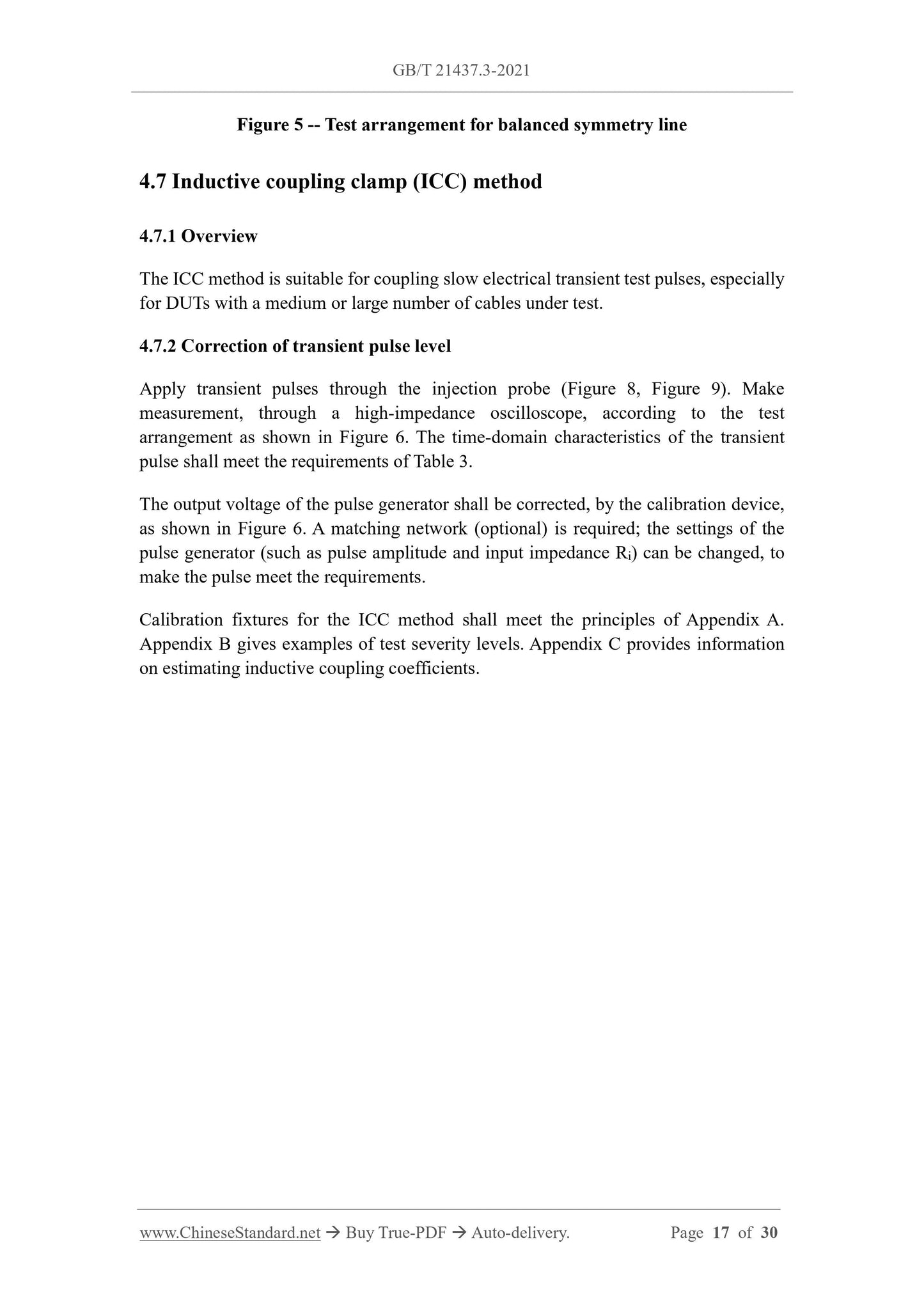
Figure 5 -- Test arrangement for balanced symmetry line
4.7 Inductive coupling clamp (ICC) method
4.7.1 Overview
The ICC method is suitable for coupling slow electrical transient test pulses, especially
for DUTs with a medium or large number of cables under test.
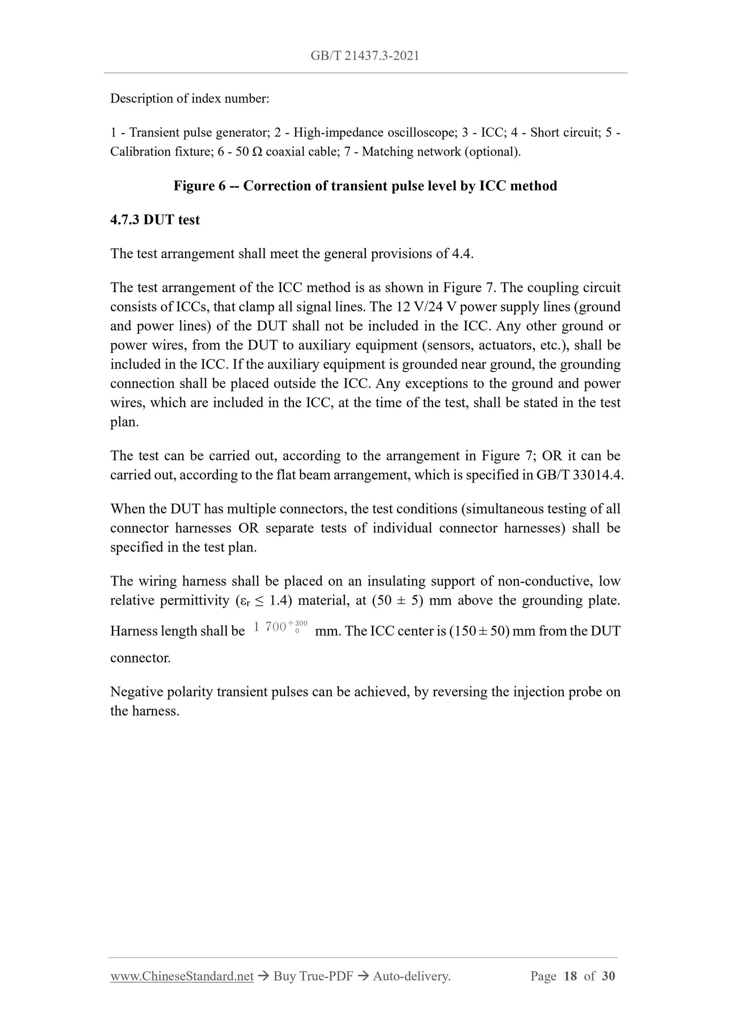
4.7.2 Correction of transient pulse level
Apply transient pulses through the injection probe (Figure 8, Figure 9). Make
measurement, through a high-impedance oscilloscope, according to the test
arrangement as shown in Figure 6. The time-domain characteristics of the transient
pulse shall meet the requirements of Table 3.
The output voltage of the pulse generator shall be corrected, by the calibration device,
as shown in Figure 6. A matching network (optional) is required; the settings of the
pulse generator (such as pulse amplitude and input impedance Ri) can be changed, to
make the pulse meet the requirements.
Calibration fixtures for the ICC method shall meet the principles of Appendix A.
Appendix B gives examples of test severity levels. Appendix C provides information
on estimating inductive coupling coefficients.
Description of index number:
1 - Transient pulse generator; 2 - High-impedance oscilloscope; 3 - ICC; 4 - Short circuit; 5 -
Calibration fixture; 6 - 50 Ω coaxial cable; 7 - Matching network (optional).
Figure 6 -- Correction of transient pulse level by ICC method
4.7....
Share