1
/
of
11
www.ChineseStandard.us -- Field Test Asia Pte. Ltd.
GB/T 21296.2-2020 English PDF (GB/T21296.2-2020)
Regular price
$245.00
Regular price
Sale price
$245.00
Unit price
/
per
Shipping calculated at checkout.
Couldn't load pickup availability
GB/T 21296.2-2020: Automatic instruments for weighing road vehicles in motion - Part 2: Weighing whole loads
Delivery: 9 seconds. Download (& Email) true-PDF + Invoice.
Get Quotation: Click GB/T 21296.2-2020 (Self-service in 1-minute)
Historical versions (Master-website): GB/T 21296.2-2020
Preview True-PDF (Reload/Scroll-down if blank)
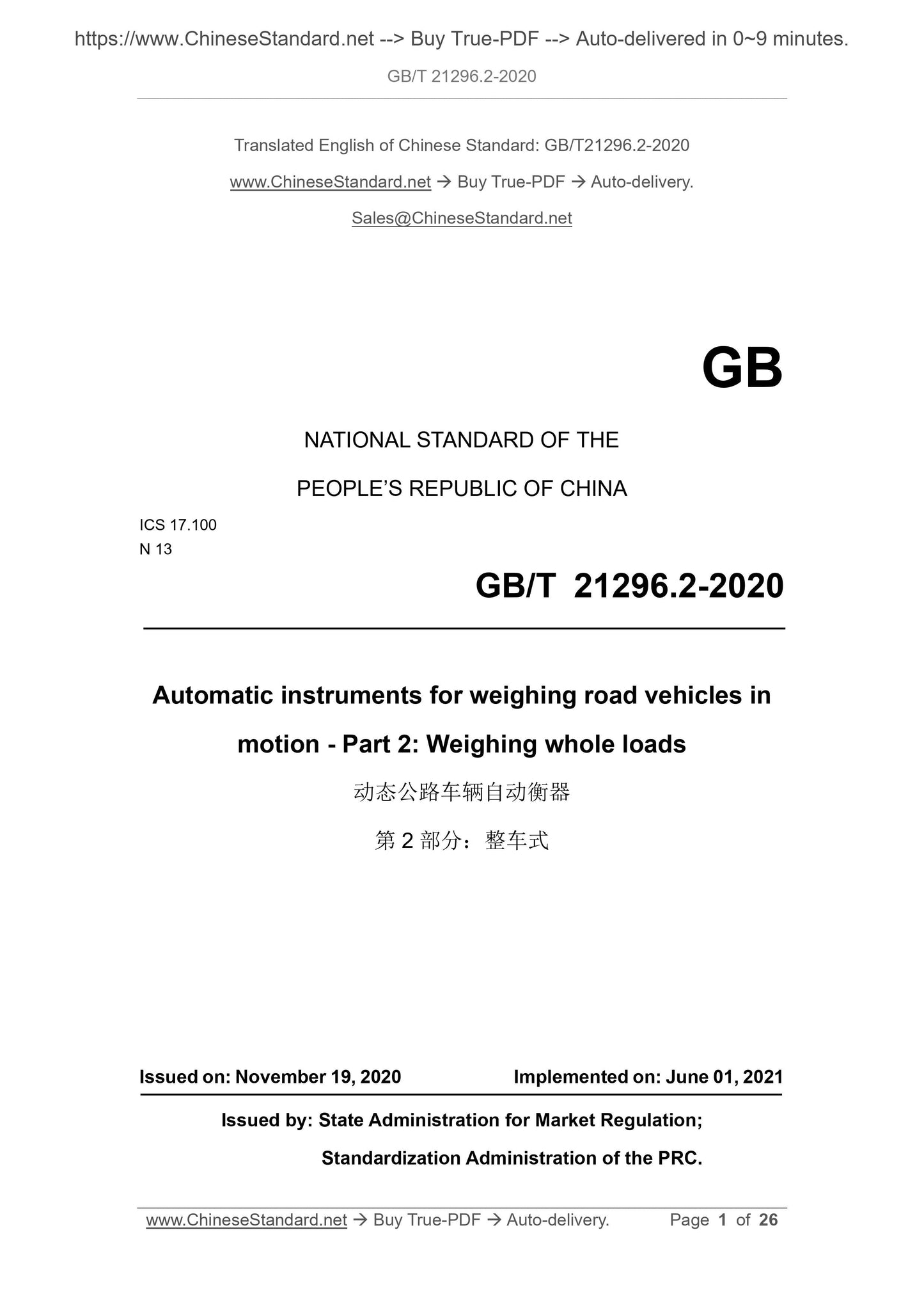
GB/T 21296.2-2020
GB
NATIONAL STANDARD OF THE
PEOPLE’S REPUBLIC OF CHINA
ICS 17.100
N 13
Automatic instruments for weighing road vehicles in
motion - Part 2: Weighing whole loads
ISSUED ON: NOVEMBER 19, 2020
IMPLEMENTED ON: JUNE 01, 2021
Issued by: State Administration for Market Regulation;
Standardization Administration of the PRC.
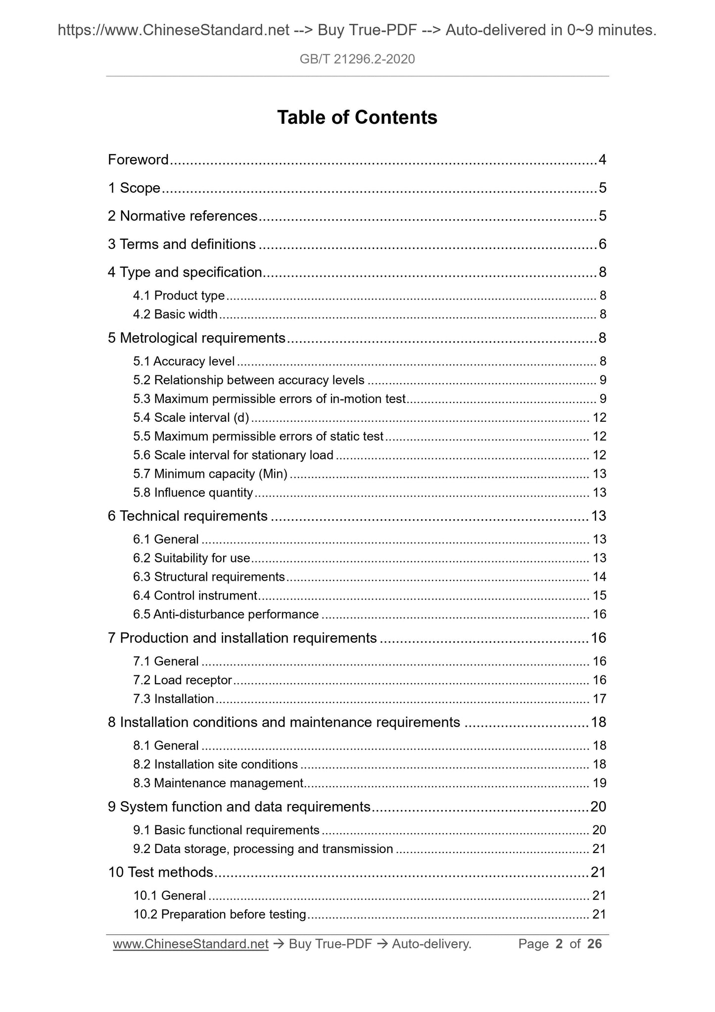
Table of Contents
Foreword ... 4
1 Scope ... 5
2 Normative references ... 5
3 Terms and definitions ... 6
4 Type and specification... 8
4.1 Product type ... 8
4.2 Basic width ... 8
5 Metrological requirements ... 8
5.1 Accuracy level ... 8
5.2 Relationship between accuracy levels ... 9
5.3 Maximum permissible errors of in-motion test ... 9
5.4 Scale interval (d) ... 12
5.5 Maximum permissible errors of static test ... 12
5.6 Scale interval for stationary load ... 12
5.7 Minimum capacity (Min) ... 13
5.8 Influence quantity ... 13
6 Technical requirements ... 13
6.1 General ... 13
6.2 Suitability for use ... 13
6.3 Structural requirements ... 14
6.4 Control instrument ... 15
6.5 Anti-disturbance performance ... 16
7 Production and installation requirements ... 16
7.1 General ... 16
7.2 Load receptor ... 16
7.3 Installation ... 17
8 Installation conditions and maintenance requirements ... 18
8.1 General ... 18
8.2 Installation site conditions ... 18
8.3 Maintenance management ... 19
9 System function and data requirements ... 20
9.1 Basic functional requirements ... 20
9.2 Data storage, processing and transmission ... 21
10 Test methods ... 21
10.1 General ... 21
10.2 Preparation before testing ... 21
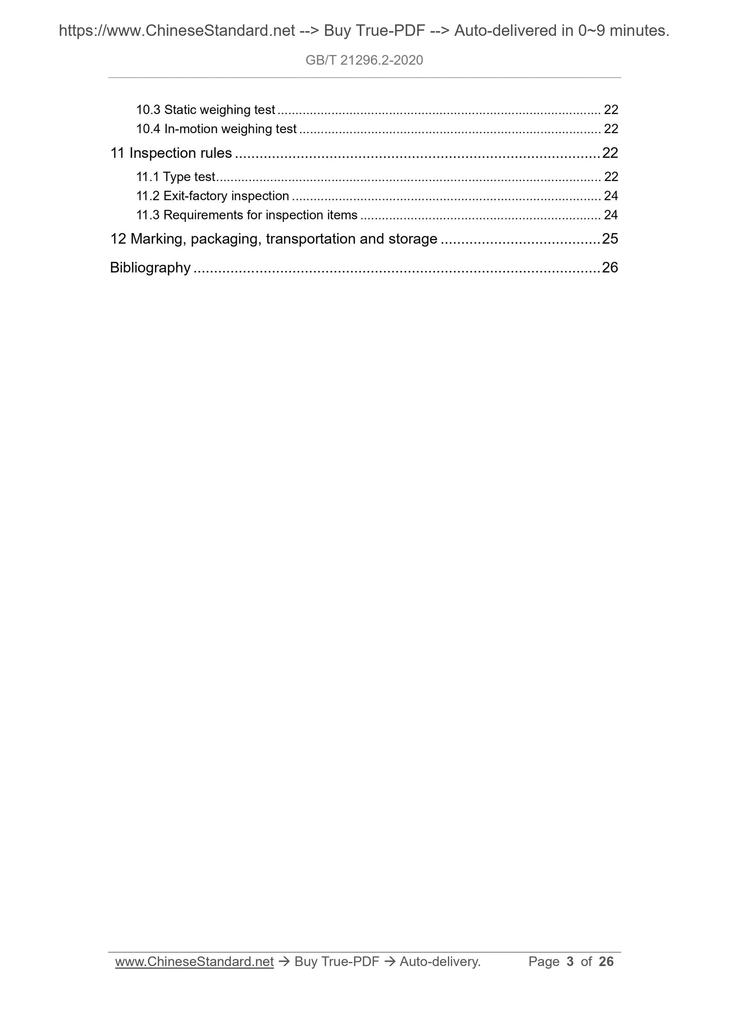
10.3 Static weighing test ... 22
10.4 In-motion weighing test ... 22
11 Inspection rules ... 22
11.1 Type test ... 22
11.2 Exit-factory inspection ... 24
11.3 Requirements for inspection items ... 24
12 Marking, packaging, transportation and storage ... 25
Bibliography ... 26
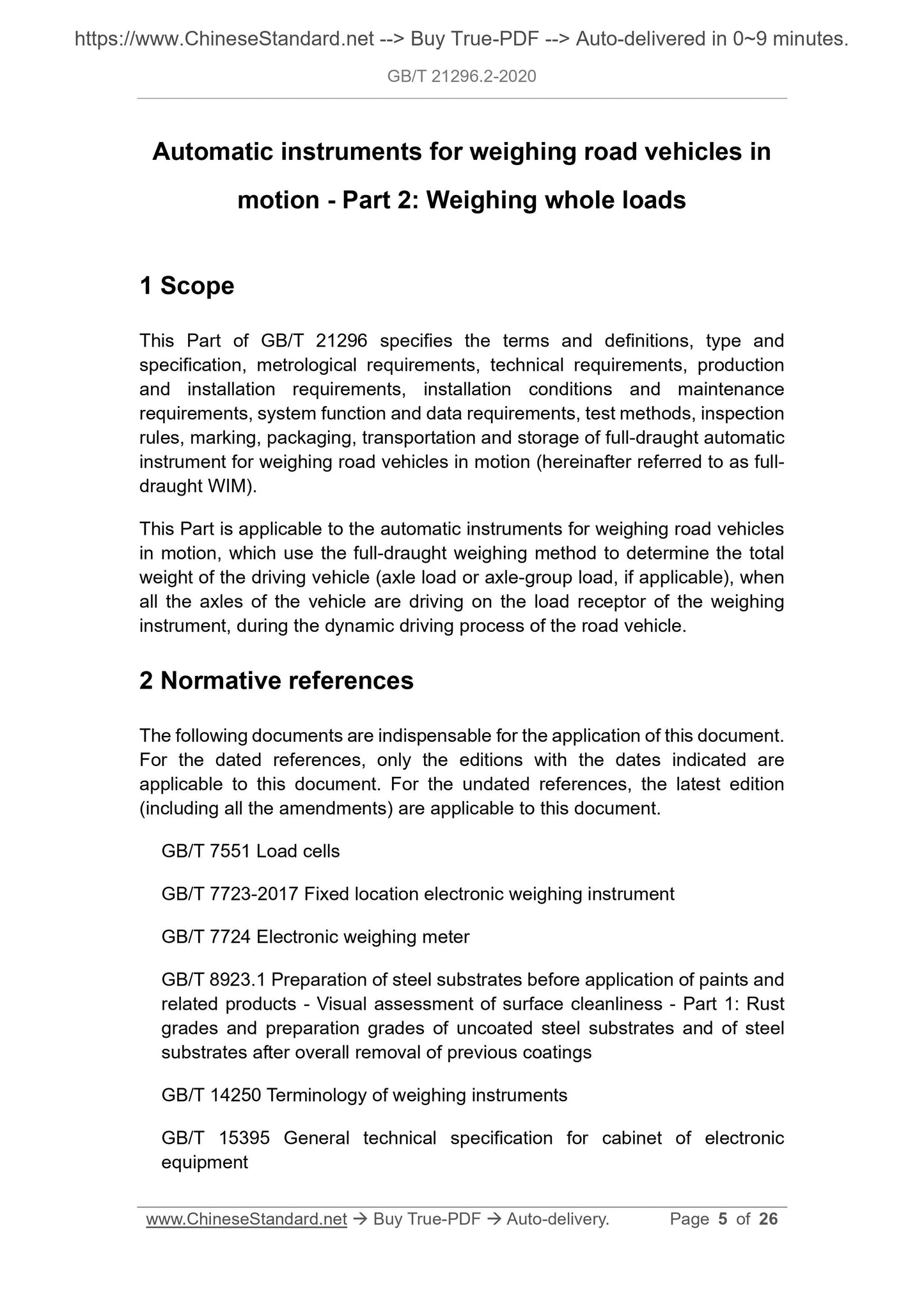
Automatic instruments for weighing road vehicles in
motion - Part 2: Weighing whole loads
1 Scope
This Part of GB/T 21296 specifies the terms and definitions, type and
specification, metrological requirements, technical requirements, production
and installation requirements, installation conditions and maintenance
requirements, system function and data requirements, test methods, inspection
rules, marking, packaging, transportation and storage of full-draught automatic
instrument for weighing road vehicles in motion (hereinafter referred to as full-
draught WIM).
This Part is applicable to the automatic instruments for weighing road vehicles
in motion, which use the full-draught weighing method to determine the total
weight of the driving vehicle (axle load or axle-group load, if applicable), when
all the axles of the vehicle are driving on the load receptor of the weighing
instrument, during the dynamic driving process of the road vehicle.
2 Normative references
The following documents are indispensable for the application of this document.
For the dated references, only the editions with the dates indicated are
applicable to this document. For the undated references, the latest edition
(including all the amendments) are applicable to this document.
GB/T 7551 Load cells
GB/T 7723-2017 Fixed location electronic weighing instrument
GB/T 7724 Electronic weighing meter
GB/T 8923.1 Preparation of steel substrates before application of paints and
related products - Visual assessment of surface cleanliness - Part 1: Rust
grades and preparation grades of uncoated steel substrates and of steel
substrates after overall removal of previous coatings
GB/T 14250 Terminology of weighing instruments
GB/T 15395 General technical specification for cabinet of electronic
equipment
Axle-group load
The sum of all axle loads in the defined axle-group.
[GB/T 21296.1-2020, definition 3.3.16]
3.5
Wheel and axle recognizer
A device used to identify the wheel and axle of a vehicle.
Note: The method installed in the weighing platform is called the embedded wheel and
axle recognizer. It can also be installed on both ends of the load receptor.
3.6
Scale interval; d
The difference, expressed in mass units, between two adjacent indicating
values or printed values of weighing-in-motion.
[GB/T 21296.1-2020, definition 3.3.23]
3.7
Controlled weighing area
The specific location where the WIM performs the weighing operation; the
location meets the installation requirements of this Part.
[GB/T 21296.1-2020, definition 3.2.1]
3.7.1
Weigh zone
The road surface area consisting of the load receptor and its aprons forward
and backward in the direction of travel.
Note 1: The length from the starting point to the end point of the weigh zone along the
driving direction is called the length of the weigh zone.
Note 2: The end of the incoming vehicle is the starting point of weigh zone. The end of the
vehicle driving away is the end point of weigh zone.
[GB/T 21296.1-2020, definition 3.2.2]
3.7.2
Apron
The rigid foundation with the physical properties of load receptor, which is
located at the two ends of the load receptor along the driving direction.
Note: The main function is to, during weighing, provide a relatively straight, relatively
horizontal and smooth travel route for the vehicle under test when it enters the load
receptor.
3.8
Operating speed; v
The average speed, the vehicle under test passing through the load receptor,
at which normal weighing-in-motion can be carried out.
[GB/T 21296.1-2020, definition 3.3.25]
3.9
Maximum operating speed; vmax
The maximum vehicle speed at which normal weighing-in-motion can be carried
out as stipulated by the design of the weighing instrument. If this speed is
exceeded, the weighing result may cause excessive relative error.
[GB/T 21296.1-2020, definition 3.3.26]
4 Type and specification
4.1 Product type
The product type shall comply with the provisions of GB/T 26389 and 4.6 of
GB/T 21296.1-2020.
4.2 Basic width
The width of the load receptor shall meet the economical width required by the
weighed vehicle. Its typical values are 3 m and 3.4 m. The length of single
section structure is generally less than 7 m.
5 Metrological requirements
5.1 Accuracy level
5.1.1 Principles for determining accuracy level
If the WIM is not suitable for liquid-loaded vehicles, it shall be clearly indicated
in the manual and nameplate.
6.2.2 The welding parts shall be welded firmly and reliably. The welds shall be
uniform, flat, free of cracks, have no welding slag. There shall be no defects
such as undercut or solder skipping. It shall meet the requirements of QB/T
1588.1.
6.2.3 The surface of the casting shall be smooth and clean. There shall be no
defects such as shrinkage porosity, cold separation, cracks, pores and slag
inclusion.
6.2.4 Forgings shall be free of defects such as cracks, interlayers, and slag
inclusions. Machinery cutting parts shall meet the requirements of QB/T 1588.2.
6.2.5 The surface of the electroplated parts shall be uniform in color. There shall
be no defects such as spots and rust.
6.2.6 Before the load receptor is painted, the surface shall be de-rusted. It shall
meet the requirements of GB/T 8923.1.
6.2.7 The paint layer on the surface shall be smooth, consistent in color, bright
and firm. The paint layer shall not have defects such as brushing, sagging,
wrinkling, air bubbles, peeling, shedding. After painting, the surface shall be
intact without exposed undercoat. It shall meet the requirements of QB/T 1588.4.
6.3 Structural requirements
6.3.1 Load receptor
The load receptor of the full-draught WIM shall be able to ensure that, all the
tyres of the tested vehicle are located on the load receptor. The load receptor
can be a single-section structure, or a multi-section structure connected
(combined) together. For the needs of axle weighing, a combination of
embedded weighing platform or multi-section load receptor can be used. There
shall be anti-skid measures on the surface of the load receptor. When the full-
draught WIM bears the load of 125% the maximum capacity, the components
of the weighing instrument shall not be permanently deformed or damaged.
6.3.2 Wheel and axle recognizer
The wheel and axle recognizer can be installed on the load receptor, as an
integrated structure. It can also be installed on both ends of the load receptor,
as a separate structure.
6.3.3 Vehicle identification device
greater than ±0.25d of the scale interval for static verification.
6.4.3 Partial load
The error of the indicating values of the same load at different positions of the
load receptor shall not be greater than the maximum permissible errors of the
verification in 5.5.
6.4.4 Discrimination
When the weighing instrument is in a balanced state, gently put on or take off
the weight, which is equivalent to 1.4 times the scale interval for static
verification. At this time, the original indicating value of the weighing instrument
shall be changed.
6.4.5 Repeatability error
The difference between the results of multiple weighings of the same load shall
not be greater than the absolute value of the maximum permissible errors under
the load.
6.5 Anti-disturbance performance
The full-draught WIM, as an electronic vehicle weighing instrument, shall meet
the requirements of electronic instrument. It shall meet the requirements of 6.4
in GB/T 21296.1-2020.
7 Production and installation requirements
7.1 General
The realization of the accuracy level of the full-draught WIM is not only related
to the design, production, and installation of the weighing instrument itself; but
also related to the conditions such as levelness, slope, curvature, and road
strength of the weigh zone. In addition, it is related to the daily maintenance of
the weighing instrument. Users shall have a correct understanding of this.
In addition to meeting the requirements of Clause 7 in GB/T 21296.1-2020, it
shall also meet the requirements of 7.2~7.3.
7.2 Load receptor
7.2.1 General
The height of the installation fixing point of each load cell of the load receptor
shall be consistent; meet the requirements of the drawing.
8 Installation conditions and maintenance
requirements
8.1 General
Users shall realize that, the realization of the performance of the full-draught
WIM not only depends on the weighing instrument itself; but also includes the
environmental conditions of the site, where the weighing instrument is installed,
and the use and maintenance level of the WIM. The performance required by
the user shall match the environmental conditions of the site installation. If
restricted by objective conditions, the installation environmental conditions
cannot meet the requirements, then the WIM shall be degraded and used.
8.2 Installation site conditions
8.2.1 Principles for selection of installation site
The selection of the installation area of the full-draught WIM follows the
following principles:
a) The road conditions before and after the installation area shall be
consistent;
b) It shall not be installed under high-voltage power lines or near radio
transmission stations and railway tracks;
c) The concrete pavement construction in the installation area shall be
implemented in accordance with the relevant requirements of the
transportation industry;
d) The asphalt pavement construction in the installation area shall be
implemented in accordance with the relevant requirements of the
transportation industry;
e) The distance between the installation location of the weighing instrument
and the entrance and exit of the highway tunnel on the same road section
shall be no less than 2 km and no less than 1 km, respectively.
8.2.2 Installation road surface conditions
The installation position of the load receptor of the full-draught WIM shall ensure
that, the center line of the load receptor is located near the center of the weigh
zone in the driving direction. The installation road surface conditions are as
specified in Table 8.
If problems are found, correct them in time.
8.3.4 Equipment lubrication and maintenance
Regularly check whether the parts of the full-draught WIM that need to be
lubricated meet the manufacturer's requirements. If not, perform lubrication
according to the requirements. Check whether the welding part of the load
receptor is un-welded. If yes, perform repair-welding in time. Check whether the
paint of the load receptor is peeling off or aging; whether the road traffic sign
lines are clear. When peeling off or aging, touch up the paint in time.
8.3.5 Pavement inspection and maintenance
Regularly check the condition of the road surface in the controlled weighing
area; to see if there are loose roads, pits, subsidence, bulges, cracks, and
chaps that affect the weighing. When it appears, fix it in time.
8.3.6 Power supply and grounding inspection
Regularly check whether the power supply of the equipment is stable and
appropriate; whether the ground wire is firmly connected; whether there is rust.
If necessary, it shall test the grounding resistance. If it does not meet the
manufacturer's requirements, take corrective measures in time.
8.3.7 Weighing accuracy check
Regularly (according to the frequency of use, laws and regulations, user or
manufacturer designation, etc.) check the weighing accuracy. When inaccuracy
is found, repair or re-adjust in time. When necessary, the control instrument can
be used for inspection.
8.3.8 Full-time equipment maintenance and management
Users shall set up full-time maintenance and management personal positions
for weighing equipment; receive corresponding professional training; formulate
care and regular inspection and maintenance systems; to ensure that the
weighing equipment is not accidentally adjusted.
9 System function and data requirements
9.1 Basic ...
Share