PayPal, credit cards. Download editable-PDF & invoice In 1 second!
GB/T 20801.6-2020 English PDF (GBT20801.6-2020)
Couldn't load pickup availability
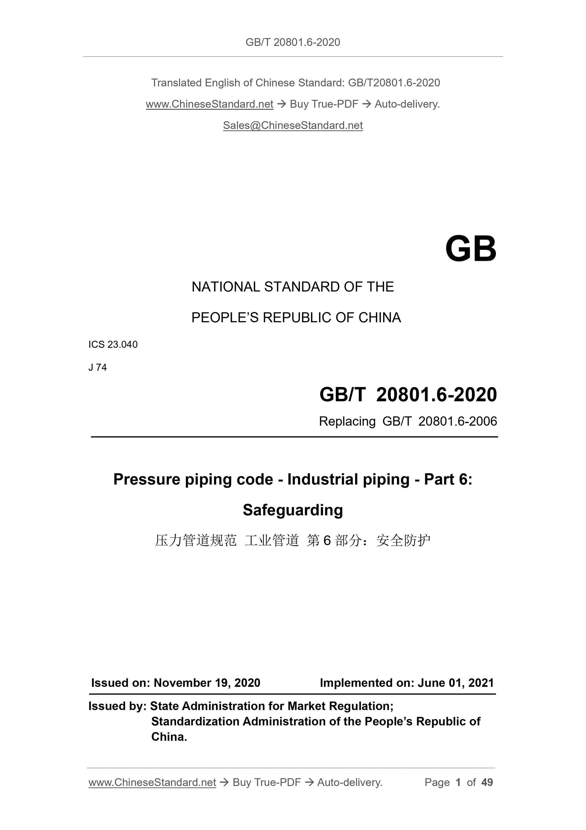
GB/T 20801.6-2020: Pressure piping code - Industrial piping - Part 6: Safeguarding
GB
NATIONAL STANDARD OF THE
PEOPLE’S REPUBLIC OF CHINA
ICS 23.040
J 74
Replacing GB/T 20801.6-2006
Pressure piping code - Industrial piping - Part 6:
Safeguarding
ISSUED ON: NOVEMBER 19, 2020
IMPLEMENTED ON: JUNE 01, 2021
Issued by: State Administration for Market Regulation;
Standardization Administration of the People’s Republic of
China.
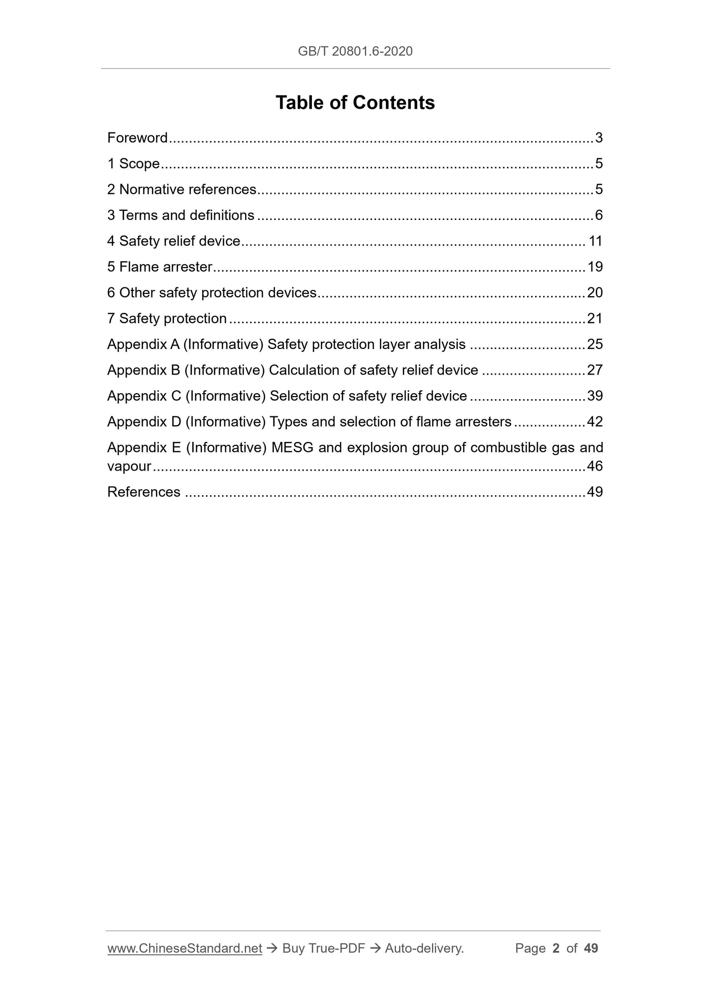
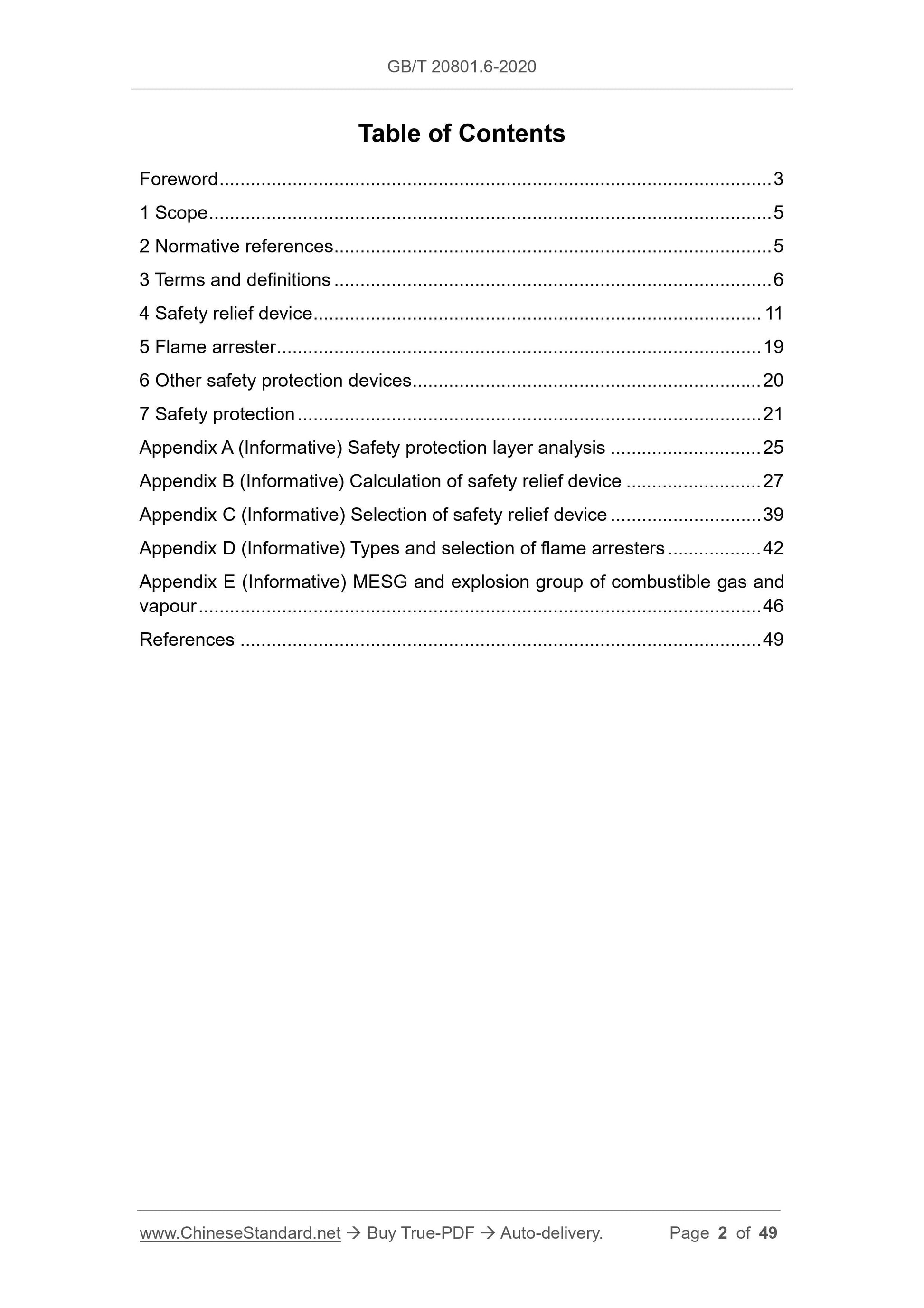
Table of Contents
Foreword ... 3
1 Scope ... 5
2 Normative references ... 5
3 Terms and definitions ... 6
4 Safety relief device ... 11
5 Flame arrester ... 19
6 Other safety protection devices ... 20
7 Safety protection ... 21
Appendix A (Informative) Safety protection layer analysis ... 25
Appendix B (Informative) Calculation of safety relief device ... 27
Appendix C (Informative) Selection of safety relief device ... 39
Appendix D (Informative) Types and selection of flame arresters ... 42 Appendix E (Informative) MESG and explosion group of combustible gas and vapour ... 46
References ... 49
Pressure piping code - Industrial piping - Part 6:
Safeguarding
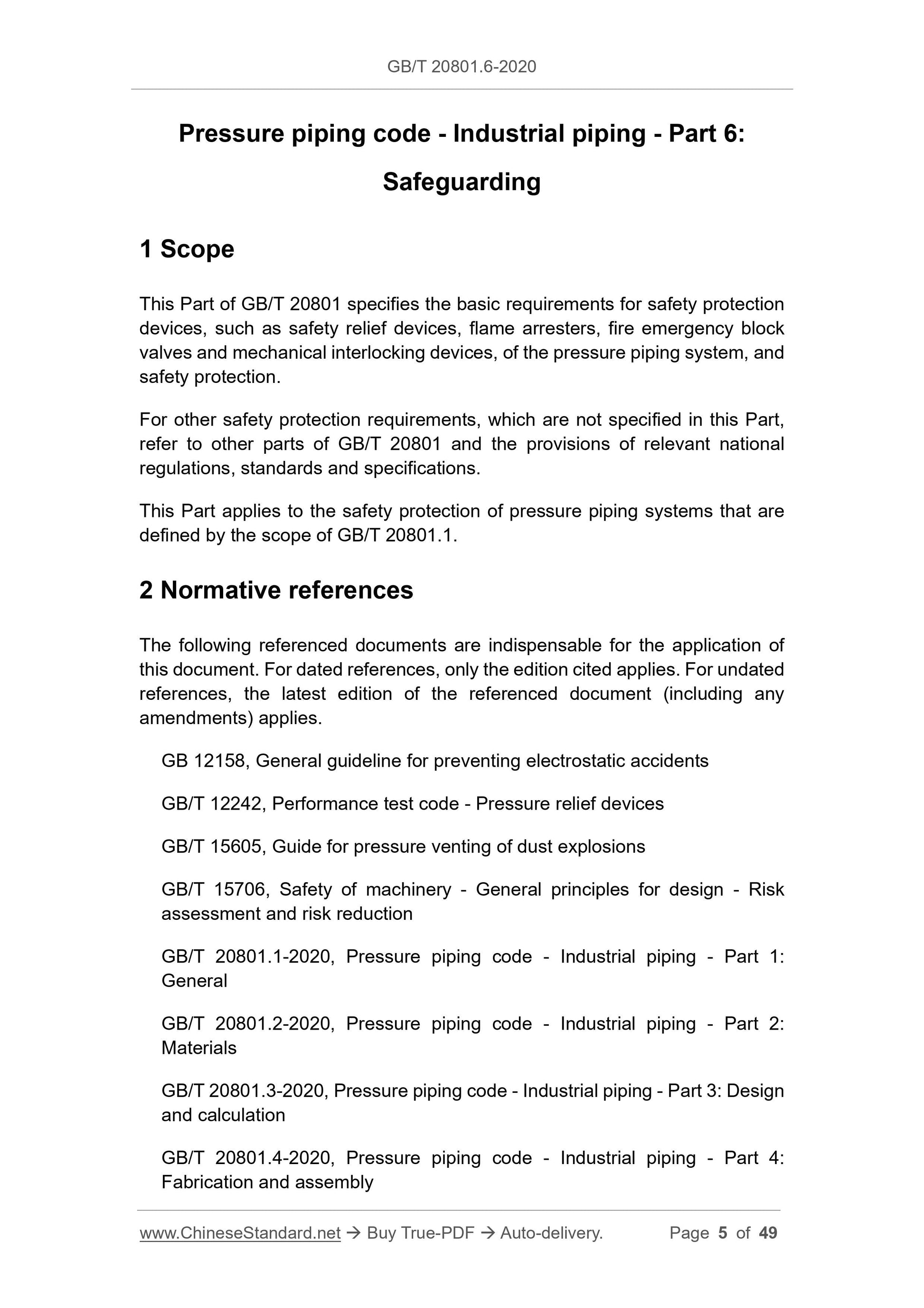
1 Scope
This Part of GB/T 20801 specifies the basic requirements for safety protection devices, such as safety relief devices, flame arresters, fire emergency block valves and mechanical interlocking devices, of the pressure piping system, and safety protection.
For other safety protection requirements, which are not specified in this Part, refer to other parts of GB/T 20801 and the provisions of relevant national regulations, standards and specifications.
This Part applies to the safety protection of pressure piping systems that are defined by the scope of GB/T 20801.1.
2 Normative references
The following referenced documents are indispensable for the application of this document. For dated references, only the edition cited applies. For undated references, the latest edition of the referenced document (including any amendments) applies.
GB 12158, General guideline for preventing electrostatic accidents
GB/T 12242, Performance test code - Pressure relief devices
GB/T 15605, Guide for pressure venting of dust explosions
GB/T 15706, Safety of machinery - General principles for design - Risk
assessment and risk reduction
GB/T 20801.1-2020, Pressure piping code - Industrial piping - Part 1:
General
GB/T 20801.2-2020, Pressure piping code - Industrial piping - Part 2:
Materials
GB/T 20801.3-2020, Pressure piping code - Industrial piping - Part 3: Design and calculation
GB/T 20801.4-2020, Pressure piping code - Industrial piping - Part 4:
Fabrication and assembly
GB/T 20801.5-2020, Pressure piping code - Industrial piping - Part 5:
Inspection and testing
GB 31571, Emission standard of pollutants for petroleum chemistry industry GB 50016, Code for fire protection design of buildings
GB 50057, Code for design protection of structures against lightning
GB 50160, Fire Prevention Code of Petrochemical Enterprise Design
GB 50984, Code for plant layout design of petrochemical enterprises
TSG ZF001, Safety Technical Supervision Regulations for Safety Valves
TSG ZF003, Safety Technical Supervision Regulations for Bursting Disc
Devices
ISO 16852, Flame arresters - Performance requirements, test methods and limits for use
ISO 23251, Petroleum, petrochemical and natural gas industries - Pressure- relieving and depressuring systems
NFPA 68, Standard on explosion protection by deflagration venting
PD CEN/TR 16793, Guide for the selection, application and use of flame
arresters
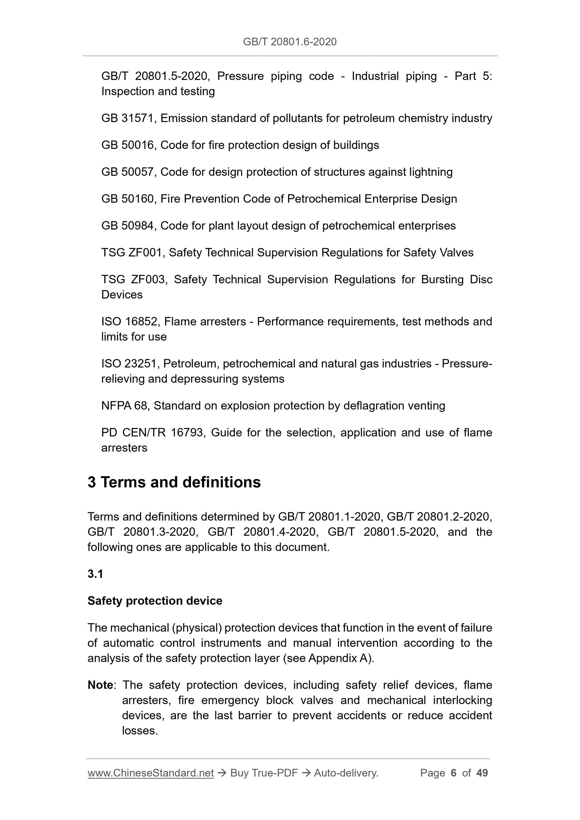
3 Terms and definitions
Terms and definitions determined by GB/T 20801.1-2020, GB/T 20801.2-2020, GB/T 20801.3-2020, GB/T 20801.4-2020, GB/T 20801.5-2020, and the
following ones are applicable to this document.
3.1
Safety protection device
The mechanical (physical) protection devices that function in the event of failure of automatic control instruments and manual intervention according to the analysis of the safety protection layer (see Appendix A).
Note: The safety protection devices, including safety relief devices, flame arresters, fire emergency block valves and mechanical interlocking
devices, are the last barrier to prevent accidents or reduce accident
losses.
The block valve that can be automatically closed under fire conditions when there is no manual intervention or external power (electricity, gas, liquid) supply; it has the properties of fire resistance, anti-static, high sealing and impact resistance.
4 Safety relief device
4.1 General provisions
4.1.1 The safety relief device shall prevent overpressure accidents in any part of the independent pressure system. Designers should use various process hazard assessment (PHA) methods to study all possible overpressure
conditions in the specific process. When identifying various overpressure conditions, the following guidelines shall be followed:
a) Any single event is credible;
b) Two related events occurring in sequence are credible;
c) Two or more unrelated independent events occurring at the same time are not credible.
4.1.2 Automatic control instruments and alarm interlocking devices shall not replace safety relief devices as the system's overpressure protection facilities. When emissions are not allowed or safety relief devices cannot be installed, all overpressure conditions can be evaluated and analyzed through process
hazard sources, and a system design method, i.e., intrinsic safety design or high integrity protection system (HIPS), can be used to eliminate the cause of system overpressure or perform system overpressure protection.
4.1.3 Equipment or piping systems that meet the following conditions shall be equipped with safety relief devices:
a) Equipment and piping systems where the design pressure is less than the pressure of the external pressure source, and the outlet may be shut off or blocked;
b) The outlet piping system of positive displacement pumps and positive displacement compressors whose outlets may be shut off;
c) The distillation tower overhead gas-phase piping system of overpressure caused by the interruption of cooling water or reflux and excessive heat input from the reboiler;
d) Equipment and piping systems where non-condensable gas accumulates
to generate overpressure;
e) The upstream piping system of the block valve or the regulating valve in the outlet piping of the heating furnace;
f) The piping system that produces thermal expansion or gasification due to ambient temperature, sunlight radiation or heat tracing after the block valves at both ends are closed;
g) The piping system on the upstream of the block valve at the reactor outlet where the cooling or stirring fails, the catalyzed impurities enter, and the reaction inhibitor is interrupted, which causes the exothermic reaction to run out of control;
h) The vapour outlet piping system of the condensing vapour turbine;
i) The outlet piping system of gas generating equipment such as vapour
generators;
j) The outlet piping system of low boiling point liquid (such as liquefied gas) containers;
k) The outlet piping system on the low-pressure side of the heat exchanger where overpressure may be caused due to pipe rupture or leakage;
l) The outlet piping system of the air cooler tube pass where the fan failure causes the cooling load to drop;
m) The outlet piping system of equipment and containers that may be
exposed to external fire.
4.1.4 The independent pressure system shall be equipped with one or more parallel safety relief devices at appropriate locations.
4.1.5 The determination of relevant pressures of the safety relief device shall meet the following requirements:
a) In an independent pressure system, the determination of relevant
pressures of the safety relief device of the equipment or piping shall be based on the design pressure of system or the maximum allowable
working pressure (MAWP), and shall meet the following requirements:
1) When installing a safety relief device, the set pressure shall not be greater than the design pressure of system or MAWP. The maximum
relief pressure of non-fire conditions shall not be greater than the larger OF 110% of the design pressure of system or MAWP AND the design
pressure of system or MAWP plus 20 kPa; the maximum relief pressure
of fire conditions shall not be greater than 121% of the design pressure of system or MAWP.
a) The block valve shall be of full bore, or the pressure drop shall not affect the normal operation and required relief capacity of the safety relief device; b) When the safety relief device is working normally, the block valve shall be locked or lead sealed in the fully open position.
4.3.2 The inlet piping of the safety relief device shall meet the following requirements:
a) The piping diameter shall not be less than the inlet size of the safety relief device; the piping length shall be as short as possible. The total
unrecoverable pressure drop of the piping should not exceed 3% of the
set pressure of the safety valve;
b) When installing a safety relief device on the outlet piping of a positive displacement compressor, the distance between the damper or orifice and the straight piping section of the safety relief device shall not be less than 10 times the piping diameter.
4.3.3 The outlet piping of the safety relief device shall meet the following requirements:
a) The outlet of the piping relieved to the atmosphere shall be located in a safe place, and the safety relief device, the relief piping and its support shall have sufficient strength to withstand the relief reaction force;
b) The back pressure of the outlet piping and main relief piping discharged to closed systems (such as exhaust funnel, flare system, collection
container or other processing system) shall not exceed the maximum back pressure allowed by the safety relief device;
c) The impact of quenching on the low-temperature embrittlement of the
piping material during the flash evaporation of low-boiling liquids such as liquefied gas shall be considered.
4.4 Selection of safety relief device
4.4.1 For the safety relief device, the relief medium, the process overpressure conditions and the performance of the safety relief device shall be considered when selecting the appropriate form of the safety relief device. See Appendix C. The selection of the safety relief device shall comply with the relevant standards.
4.4.2 Safety relief device products shall comply with the relevant standards such as TSG ZF001, TSG ZF003 and GB/T 12242.
5 Flame arrester
5.1 Application of flame arrester
5.1.1 Flame arrestor products and applications shall comply with relevant standards such as ISO 16852 and PD CEN/TR 16793.
5.1.2 In the process equipment, there are a large number of non-electrical equipment and piping systems in potentially explosive environments. Flame arrestor is the main safety protection device for explosion-proof of non-electrical equipment. It has the function of preventing explosion, preventing explosion from spreading through piping, and preventing deflagration from developing into detonation. Refer to Appendix D for the types and selection of flame arresters. 5.2 Flame arrestor settings
The following equipment and piping systems shall be equipped with flame arresters:
a) Flammable liquid atmospheric storage tanks, as well as the vents and breathing valve inlets and outlets of cryogenic storage tanks such as liquid hydrocarbons and LNG, and their gas-phase connecting piping;
b) Inlets of combustion equipment such as torch, incinerator, and oxidation furnace;
c) Inlets and outlets of mechanical equipment such as fans, vacuum pumps, compressors, etc. with a continuous ignition source and zone 0;
d) Breathing valves of terminal stations, tankers and tank cars for loading and unloading flammable liquids or gases, as well as gas replacement and balance piping;
e) Breathing valves and gas main piping of gas storage tanks in biogas
systems, sewage treatment and landfill gas systems;
f) Parallel equipment systems (such as reactors) for processing combustible chemicals, combustible solvent recovery systems, combustible gas and
vapor recovery systems, single equipment or system gas and vapor
outlets of combustible tail gas treatment systems, and inlets of the
manifold to processing equipment such as torches, incinerators, oxidation furnaces, activated carbon adsorption tanks.
g) Outlets of the reactor or container, which may undergo uncontrolled
exothermic reaction, spontaneous combustion, or self-decomposition, to
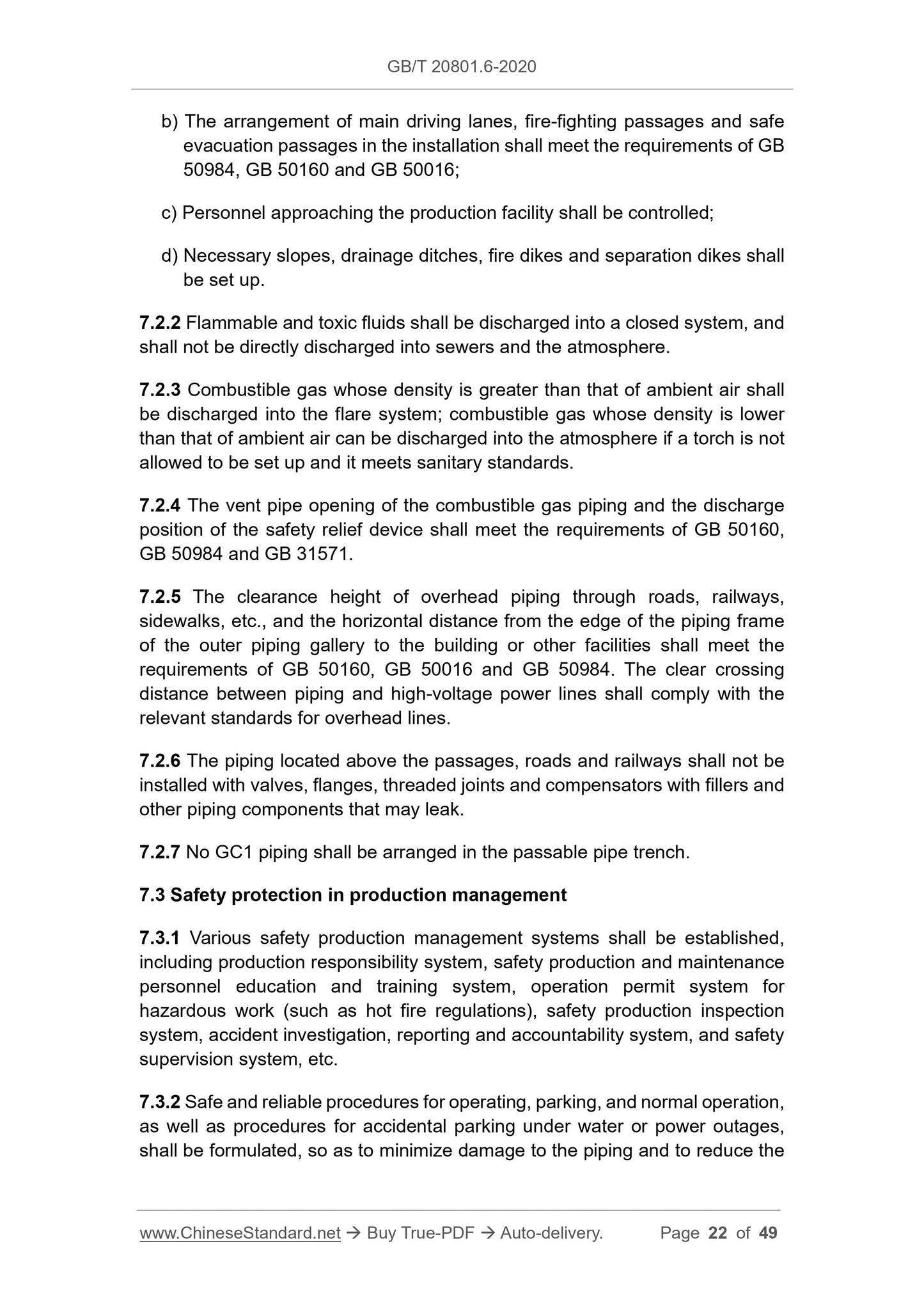
the atmosphere or a container that is not resistant to explosive pressure; b) The arrangement of main driving lanes, fire-fighting passages and safe evacuation passages in the installation shall meet the requirements of GB 50984, GB 50160 and GB 50016;
c) Personnel approaching the production facility shall be controlled;
d) Necessary slopes, drainage ditches, fire dikes and separation dikes shall be set up.
7.2.2 Flammable and toxic fluids shall be discharged into a closed system, and shall not be directly discharged into sewers and the atmosphere.
7.2.3 Combustible gas whose density is greater than that of ambient air shall be discharged into the flare system; combustible gas whose density is lower than that of ambient air can be discharged into the atmosphere if a torch is not allowed to be set up and it meets sanitary standards.
7.2.4 The vent pipe opening of the combustible gas piping and the discharge position of the safety relief device shall meet the requirements of GB 50160, GB 50984 and GB 31571.
7.2.5 The clearance height of overhead piping through roads, railways,
sidewalks, etc., and the horizontal distance from the edge of the piping frame of the outer piping gallery to the building or other facilities shall meet the requirements of GB 50160, GB 50016 and GB 50984. The clear crossing
distance between piping and high-voltage power lines shall comply with the relevant standards for overhead lines.
7.2.6 The piping located above the passages, roads and railways shall not be installed with valves, flanges, threaded joints and compensators with fillers and other piping components that may leak.
7.2.7 No GC1 piping shall be arranged in the passable pipe trench.
7.3 Safety protection in production management
7.3.1 Various safety production management systems shall be established, including production responsibility system, safety production and maintenance personnel education and training system, operation permit system for
hazardous work (such as hot fire regulations), safety production inspection system, accident investigation, reporting and accountability system, and safety supervision system, etc.
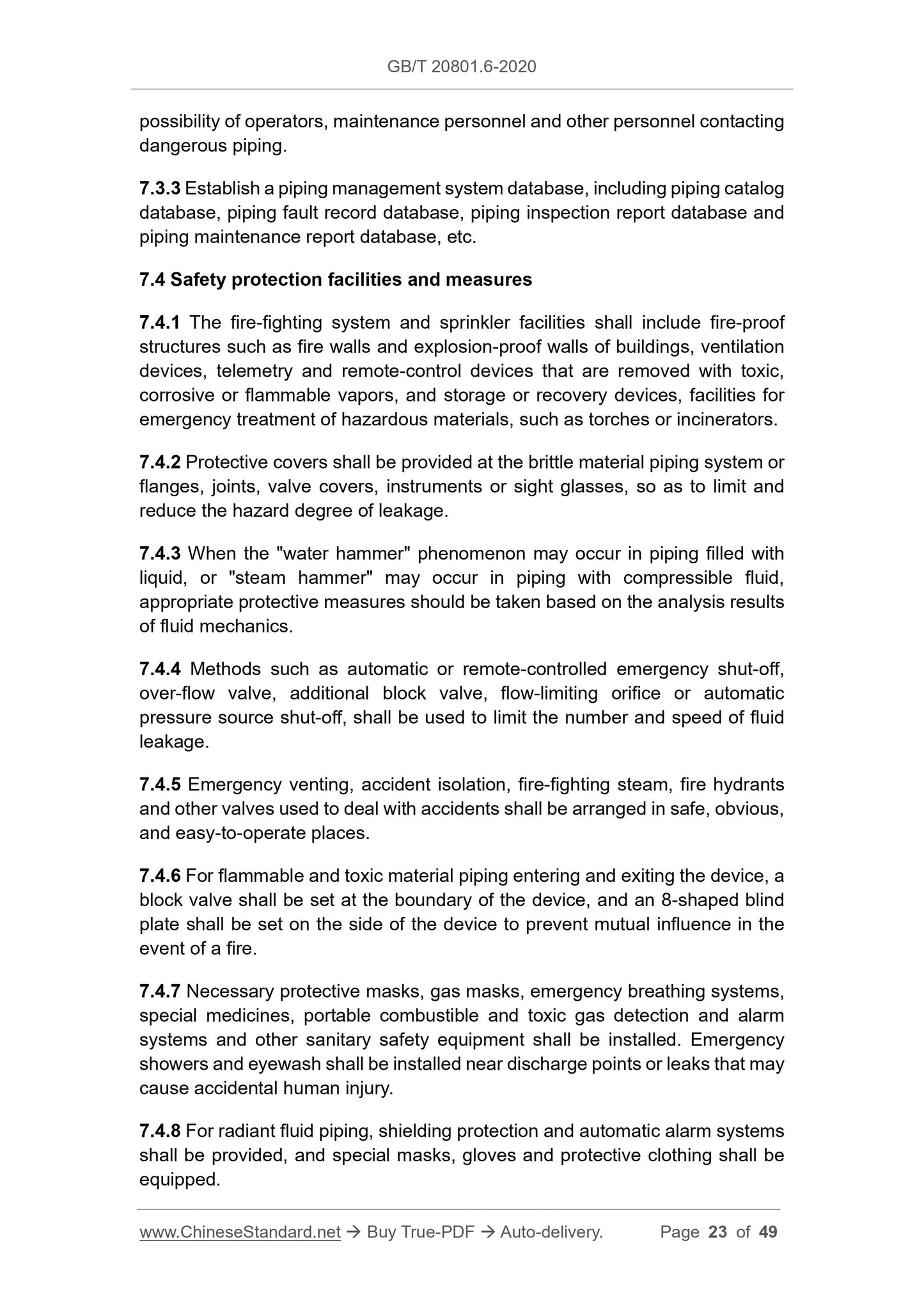
7.3.2 Safe and reliable procedures for operating, parking, and normal operation, as well as procedures for accidental parking under water or power outages, shall be formulated, so as to minimize damage to the piping and to reduce the possibility of operators, maintenance personnel and other personnel contacting dangerous piping.
7.3.3 Establish a piping management system database, including piping catalog database, piping fault record database, piping inspection report database and piping maintenance report database, etc.
7.4 Safety protection facilities and measures
7.4.1 The fire-fighting system and sprinkler facilities shall include fire-proof structures such as fire walls and explosion-proof walls of buildings, ventilation devices, telemetry and remote-control devices that are removed with toxic, corrosive or flammable vapors, and storage or recovery devices, facilities for emergency treatment of hazardous materials, such as torches or incinerators. 7.4.2 Protective covers shall be provided at the brittle material piping system or flanges, joints, valve covers, instruments or sight glasses, so as to limit and reduce the hazard degree of leakage.
7.4.3 When the "water hammer" phenomenon may occur in piping filled with liquid, or "steam hammer" may occur in piping with compressible fluid,
appropriate protective measures should be taken based on the analysis results of fluid mechanics.
7.4.4 Methods such as automatic or remote-controlled emergency shut-off, over-flow valve, additional block valve, flow-limiting orifice or automatic pressure source shut-off, shall be used to limit the number and speed of fluid leakage.
7.4.5 Emergency venting, accident isolation, fire-fighting steam, fire hydrants and other valves used to deal with accidents shall be arranged in safe, obvious, and easy-to-operate places.
7.4.6 For flammable and toxic material piping entering and exiting the device, a block valve shall be set at the boundary of the device, and an 8-shaped blind plate shall be set on the side of the device to prevent mutual influence in the event of a fire.
7.4.7 Necessary protective masks, gas masks, emergency breathing systems, special medicines, portable combustible and toxic gas detection and alarm systems and other sanitary safety equipment shall be installed. Emergency showers and eyewash shall be installed near discharge points or leaks that may cause accidental human injury.
7.4.8 For radiant fluid piping, shielding protection and automatic alarm systems shall be provided, and special masks, gloves and protective clothing shall be equipped.
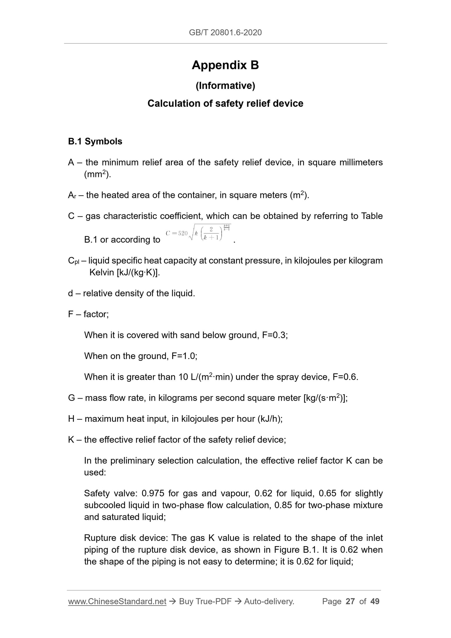
Appendix B
(Informative)
Calculation of safety relief device
B.1 Symbols
A – the minimum relief area of the safety relief device, in square millimeters (mm2).
Ar – the heated area of the container, in square meters (m2).
C – gas characteristic coefficient, which can be obtained by referring to Table B.1 or according to .
Cpl – liquid specific heat capacity at constant pressure, in kilojoules per kilogram Kelvin [kJ/(kg∙K)].
d – relative density of the liquid.
F – factor;
When it is covered with sand below ground, F=0.3;
When on the ground, F=1.0;
When it is greater than 10 L/(m2·min) under the spray device, F=0.6.
G – mass flow rate, in kilograms per second square meter [kg/(s·m2)];
H – maximum heat input, in kilojoules per hour (kJ/h);
K – the effective relief factor of the safety relief device;
In the preliminary selection calculation, the effective relief factor K can be used:
Safety valve: 0.975 for gas and vapour, 0.62 for liquid, 0.65 for slightly subcooled liquid in two-phase flow calculation, 0.85 for two-phase mixture and saturated liquid;
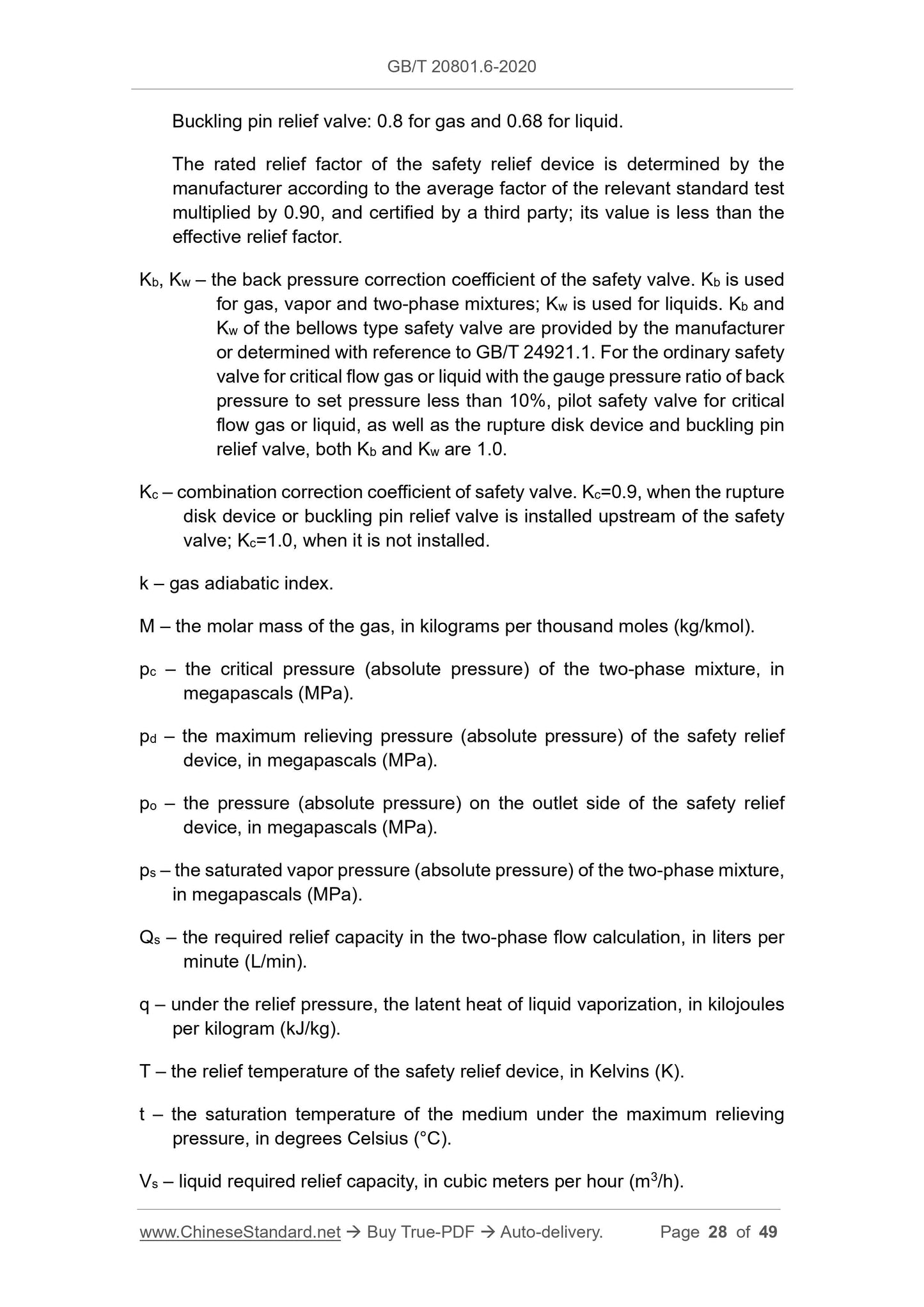
Rupture disk device: The gas K value is related to the shape of the inlet piping of the rupture disk device, as shown in Figure B.1. It is 0.62 when the shape of the piping is not easy to determine; it is 0.62 for liquid; Buckling pin relief valve: 0.8 for gas and 0.68 for liquid.
The rated relief factor of the safety relief device is determined by the manufacturer according to the average factor of the relevant standard test multiplied by 0.90, and certified by a third party; its value is less than the effective relief factor.
Kb, Kw – the back pressure correction coefficient of the safety valve. Kb is used for gas, vapor and two-phase mixtures; Kw is used for liquids. Kb and
Kw of the bellows type safety valve are provided by the manufacturer
or determined with reference to GB/T 24921.1. For the ordinary safety
valve for critical flow gas or liquid with the gauge pressure ratio of back pressure to set pressure less than 10%, pilot safety valve for critical flow gas or liquid, as well as the rupture disk device and buckling pin relief valve, both Kb and Kw are 1.0.
Kc – combination correction coefficient of safety valve. Kc=0.9, when the rupture disk device or buckling pin relief valve is installed upstream of the safety valve; Kc=1.0, when it is not installed.
k – gas adiabatic index.
M – the molar mass of the gas, in kilograms per thousand moles (kg/kmol). pc – the critical pressure (absolute pressure) of the two-phase mixture, in megapascals (MPa).
pd – the maximum relieving pressure (absolute pressure) of the safety relief device, in megapascals (MPa).
po – the pressure (absolute pressure) on the outlet side of the safety relief device, in megapascals (MPa).
ps – the saturated vapor pressure (absolute pressure) of the two-phase mixture, in megapascals (MPa).
Qs – the required relief capacity in the two-phase flow calculation, in liters per minute (L/min).
q – under the relief pressure, the latent heat of liquid vaporization, in kilojoules per kilogram (kJ/kg).
T – the relief temperature of the safety relief device, in Kelvins (K). t – the saturation temperature of the medium under the maximum relieving pressure, in degrees Celsius (°C).
Vs – liquid required relief capacity, in cubic meters per hour (m3/h).
Share