1
/
of
9
www.ChineseStandard.us -- Field Test Asia Pte. Ltd.
GB/T 20735-2006 English PDF (GB/T20735-2006)
Regular price
$85.00
Regular price
Sale price
$85.00
Unit price
/
per
Shipping calculated at checkout.
Couldn't load pickup availability
GB/T 20735-2006: Pressure regulator of CNG vehicles
Delivery: 9 seconds. Download (& Email) true-PDF + Invoice.
Get Quotation: Click GB/T 20735-2006 (Self-service in 1-minute)
Historical versions (Master-website): GB/T 20735-2006
Preview True-PDF (Reload/Scroll-down if blank)
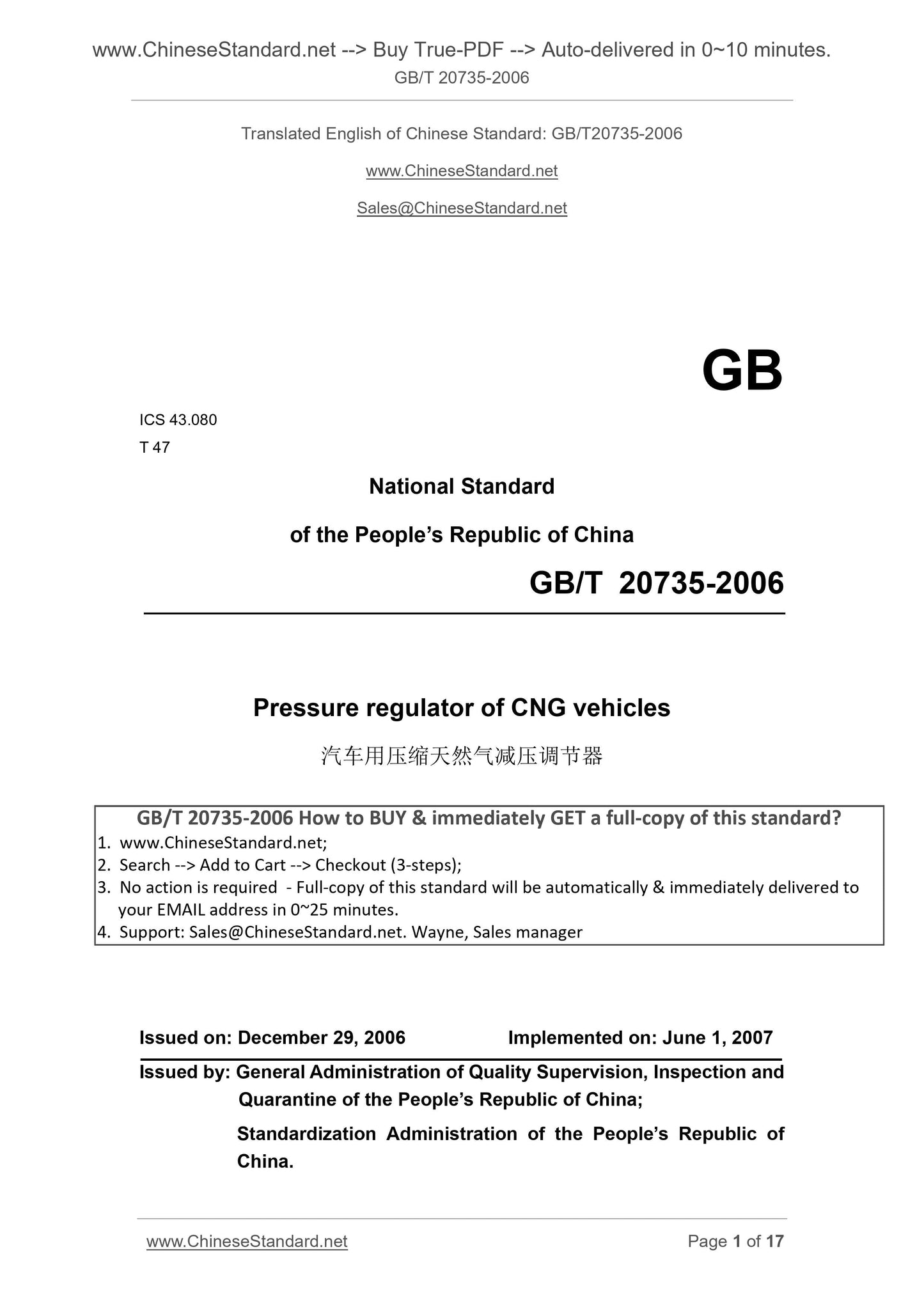
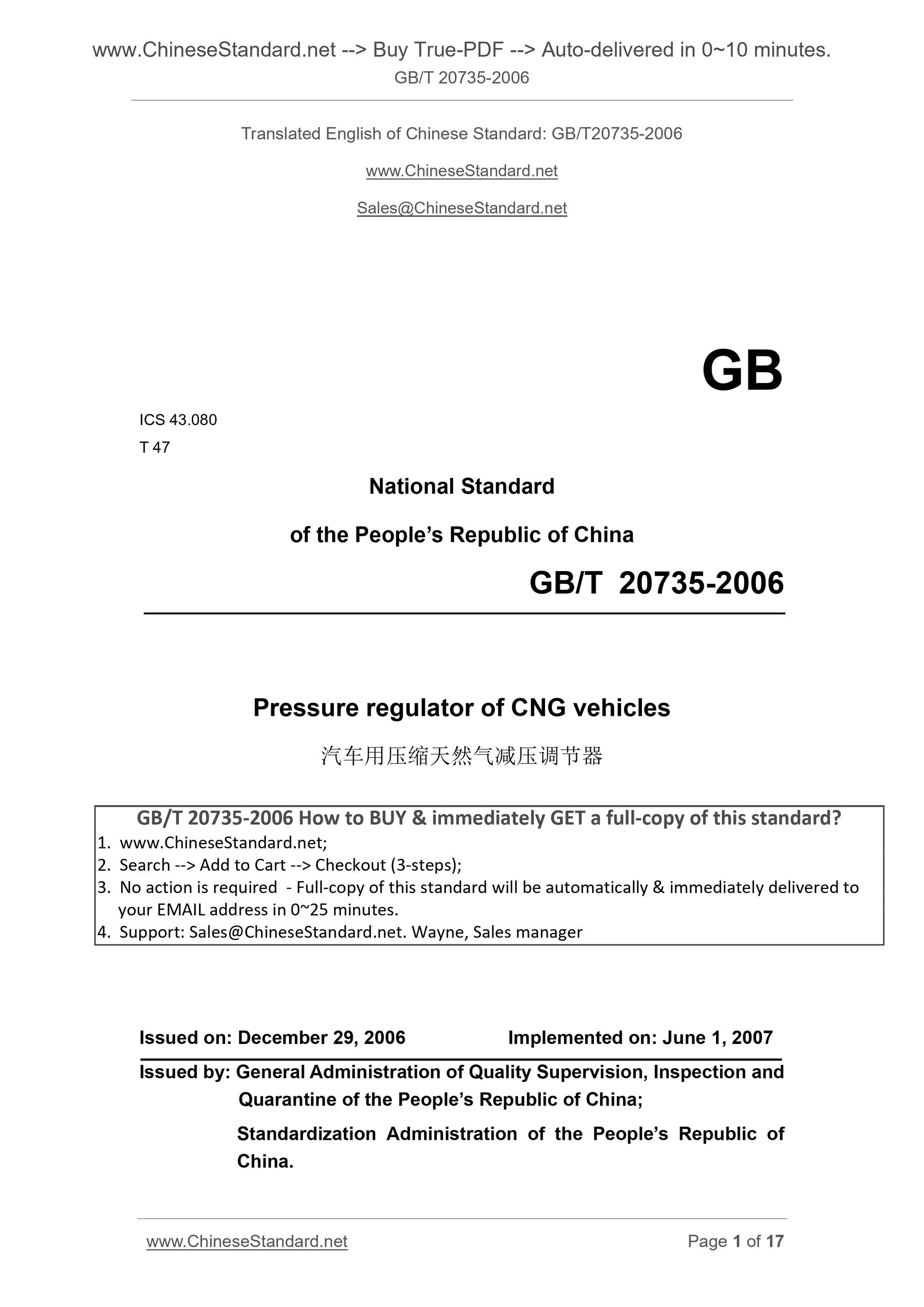
GB/T 20735-2006
GB
ICS 43.080
T 47
National Standard
of the People’s Republic of China
Pressure regulator of CNG vehicles
ISSUED ON. DECEMBER 29, 2006
IMPLEMENTED ON. JUNE 1, 2007
Issued by. General Administration of Quality Supervision, Inspection and
Quarantine of the People’s Republic of China;
Standardization Administration of the People’s Republic of
China.
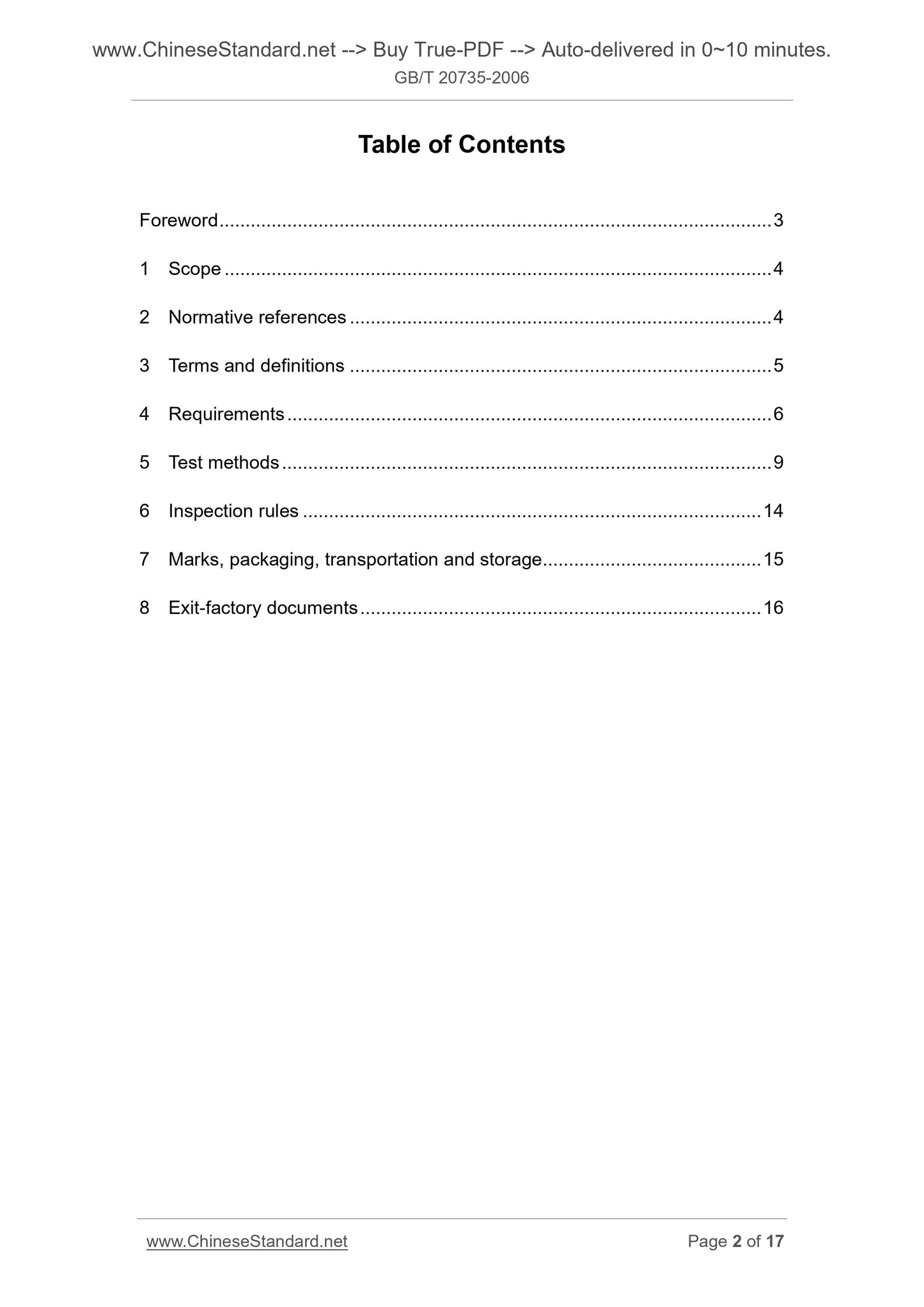
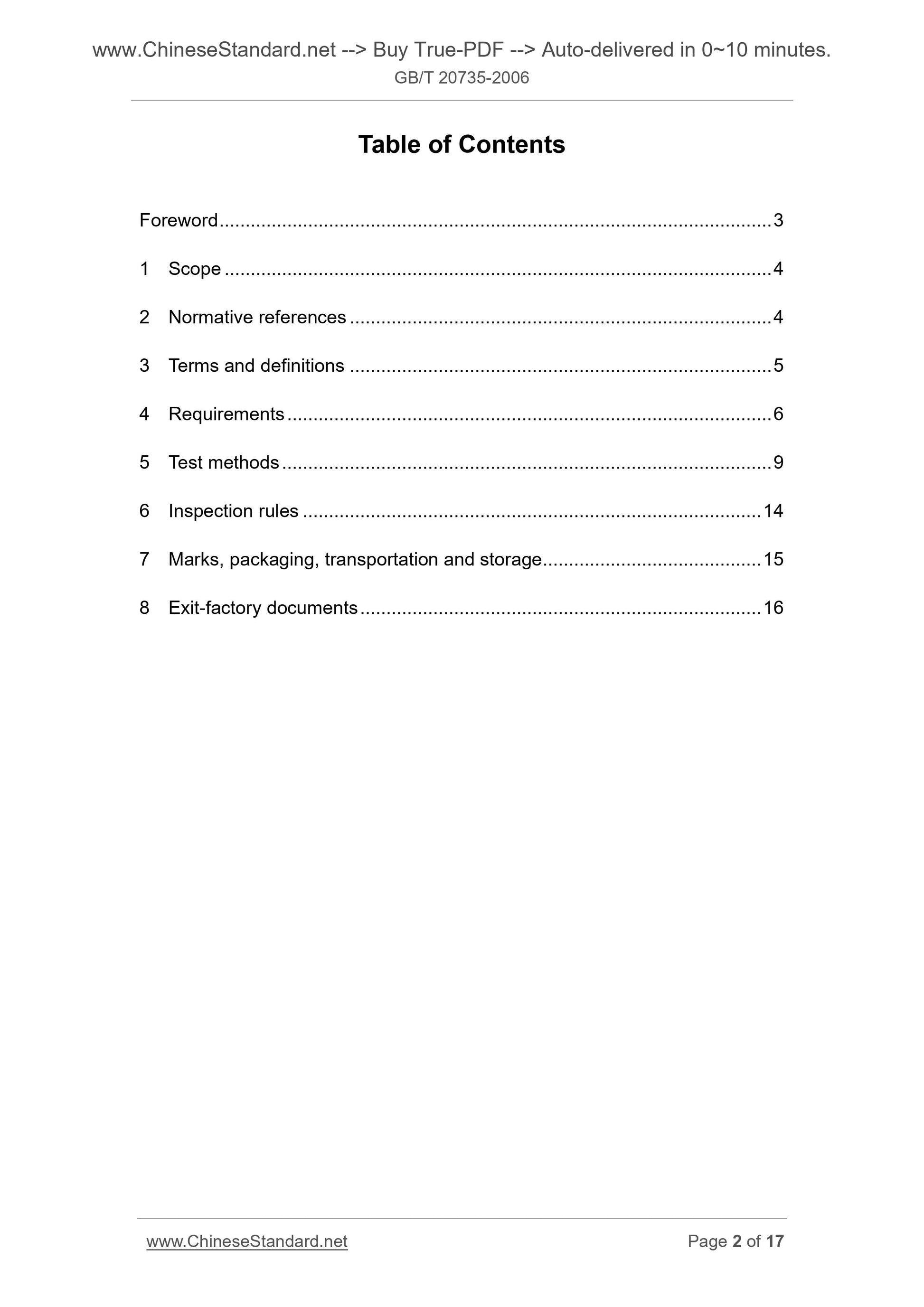
Table of Contents
Foreword ... 3
1 Scope ... 4
2 Normative references ... 4
3 Terms and definitions ... 5
4 Requirements ... 6
5 Test methods ... 9
6 Inspection rules ... 14
7 Marks, packaging, transportation and storage ... 15
8 Exit-factory documents ... 16
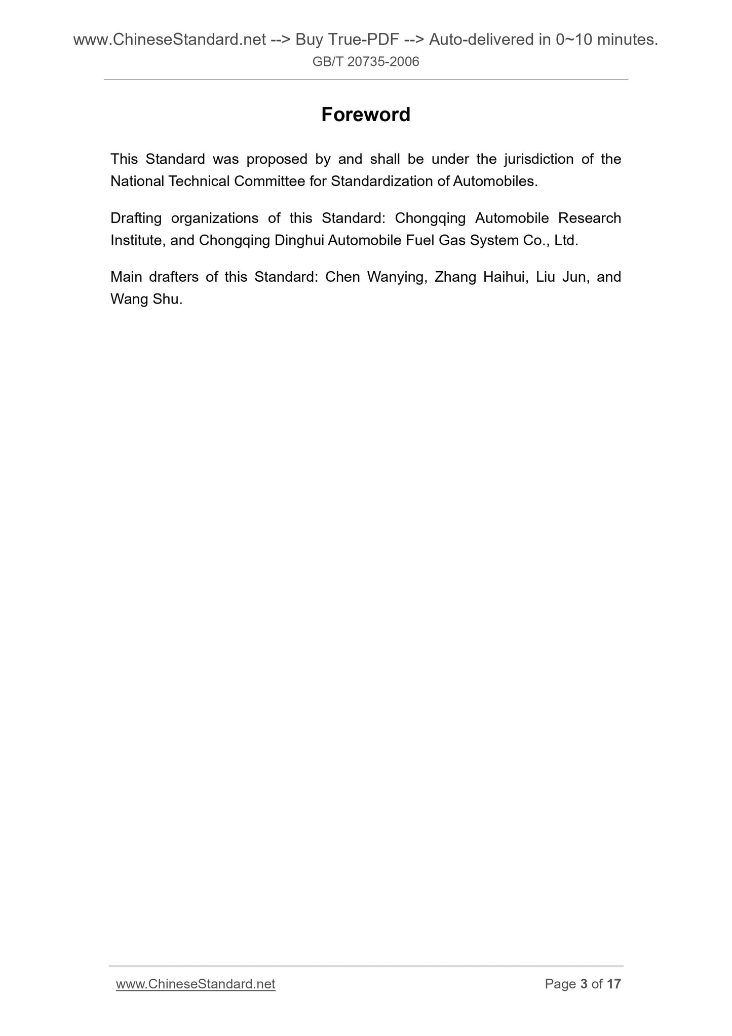
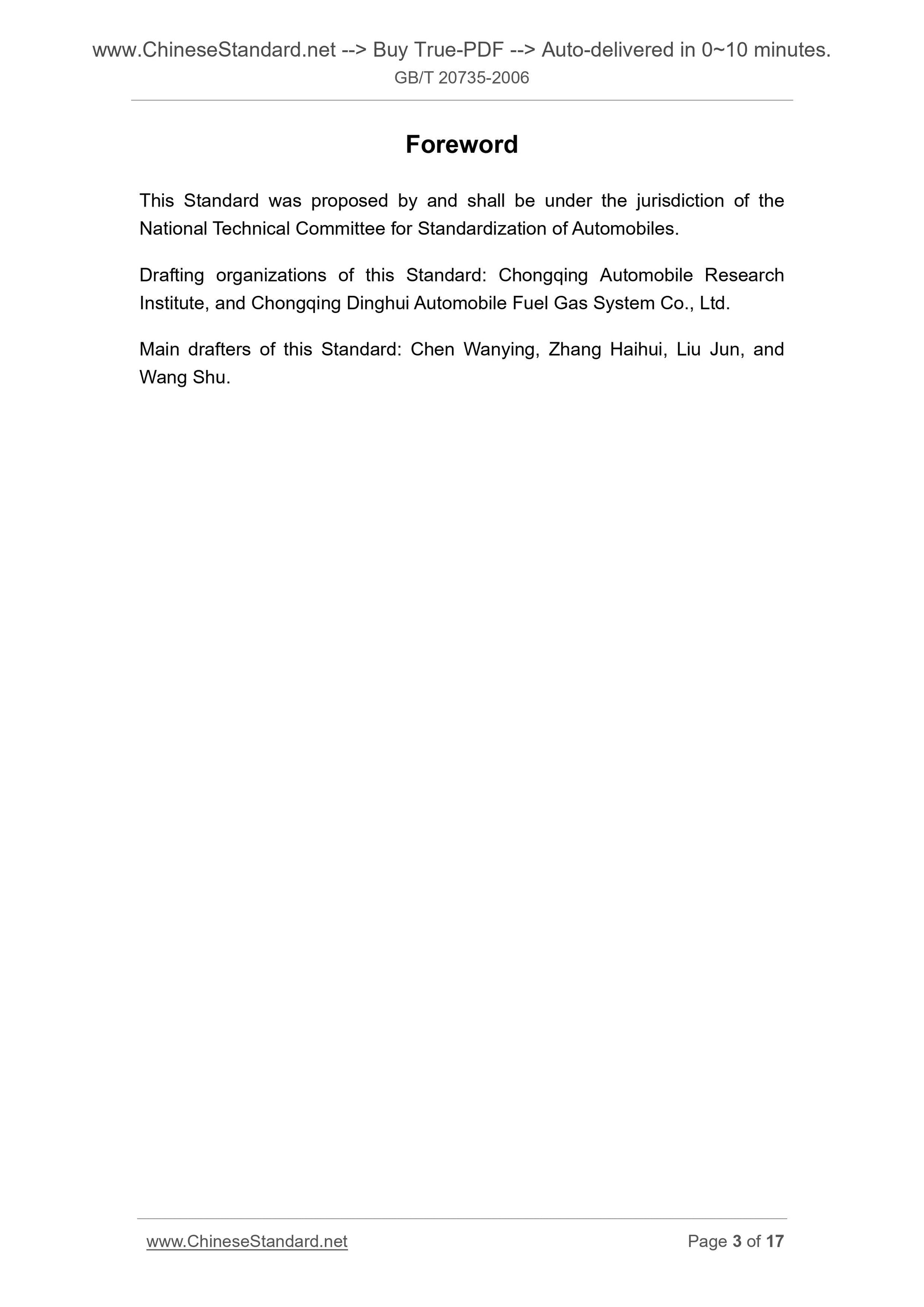
Foreword
This Standard was proposed by and shall be under the jurisdiction of the
National Technical Committee for Standardization of Automobiles.
Drafting organizations of this Standard. Chongqing Automobile Research
Institute, and Chongqing Dinghui Automobile Fuel Gas System Co., Ltd.
Main drafters of this Standard. Chen Wanying, Zhang Haihui, Liu Jun, and
Wang Shu.
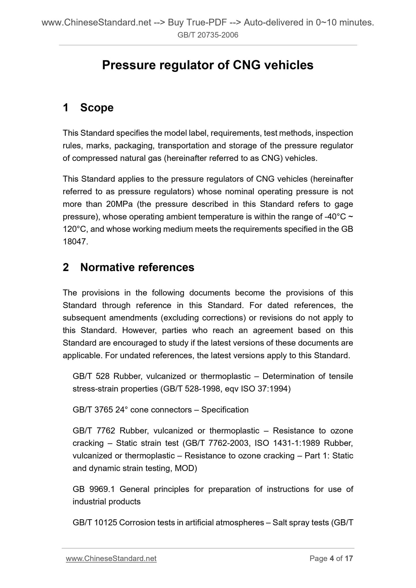
Pressure regulator of CNG vehicles
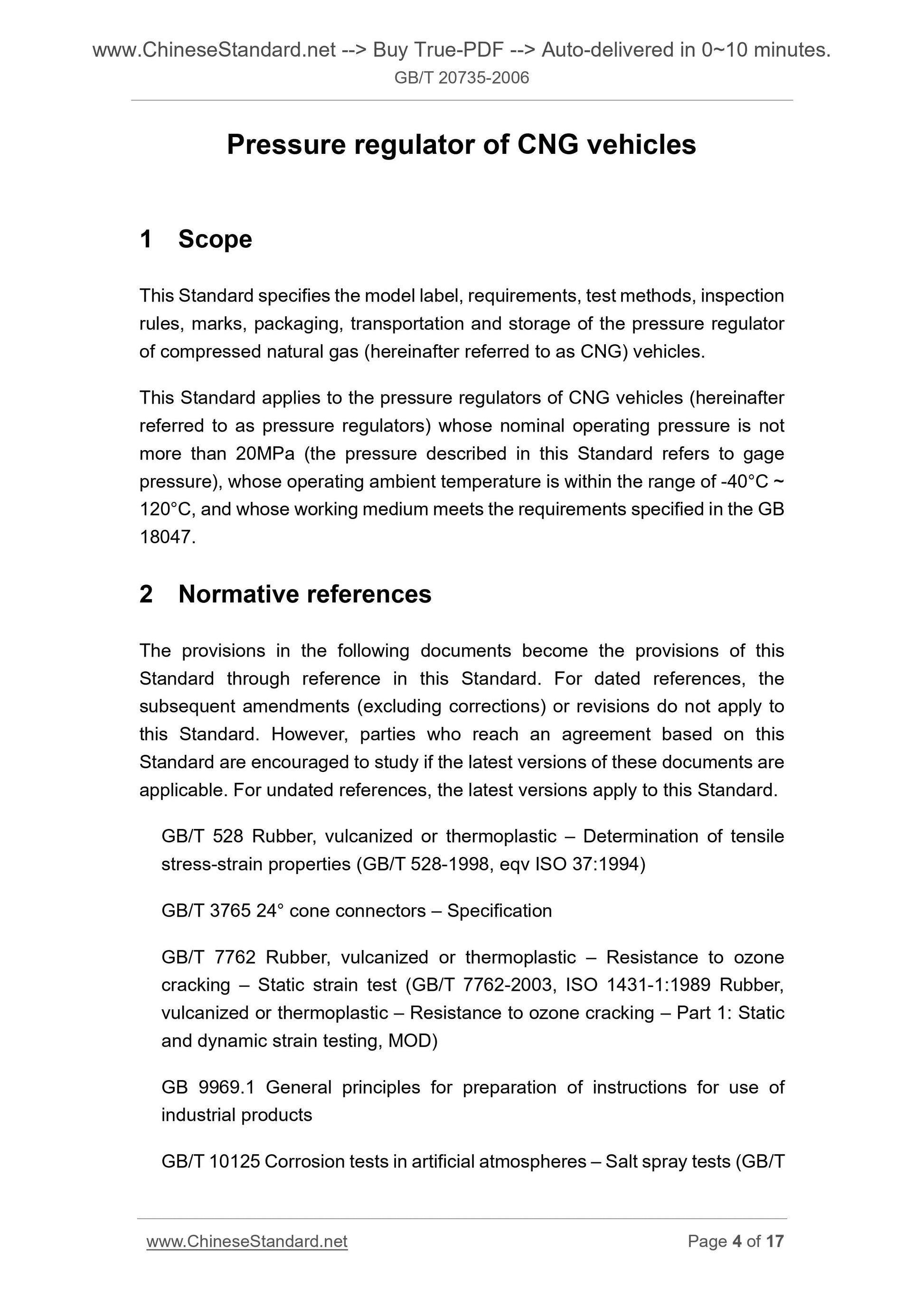
1 Scope
This Standard specifies the model label, requirements, test methods, inspection
rules, marks, packaging, transportation and storage of the pressure regulator
of compressed natural gas (hereinafter referred to as CNG) vehicles.
This Standard applies to the pressure regulators of CNG vehicles (hereinafter
referred to as pressure regulators) whose nominal operating pressure is not
more than 20MPa (the pressure described in this Standard refers to gage
pressure), whose operating ambient temperature is within the range of -40°C ~
120°C, and whose working medium meets the requirements specified in the GB
18047.
2 Normative references
The provisions in the following documents become the provisions of this
Standard through reference in this Standard. For dated references, the
subsequent amendments (excluding corrections) or revisions do not apply to
this Standard. However, parties who reach an agreement based on this
Standard are encouraged to study if the latest versions of these documents are
applicable. For undated references, the latest versions apply to this Standard.
GB/T 528 Rubber, vulcanized or thermoplastic – Determination of tensile
stress-strain properties (GB/T 528-1998, eqv ISO 37.1994)
GB/T 3765 24° cone connectors – Specification
GB/T 7762 Rubber, vulcanized or thermoplastic – Resistance to ozone
cracking – Static strain test (GB/T 7762-2003, ISO 1431-1.1989 Rubber,
vulcanized or thermoplastic – Resistance to ozone cracking – Part 1. Static
and dynamic strain testing, MOD)
GB 9969.1 General principles for preparation of instructions for use of
industrial products
GB/T 10125 Corrosion tests in artificial atmospheres – Salt spray tests (GB/T
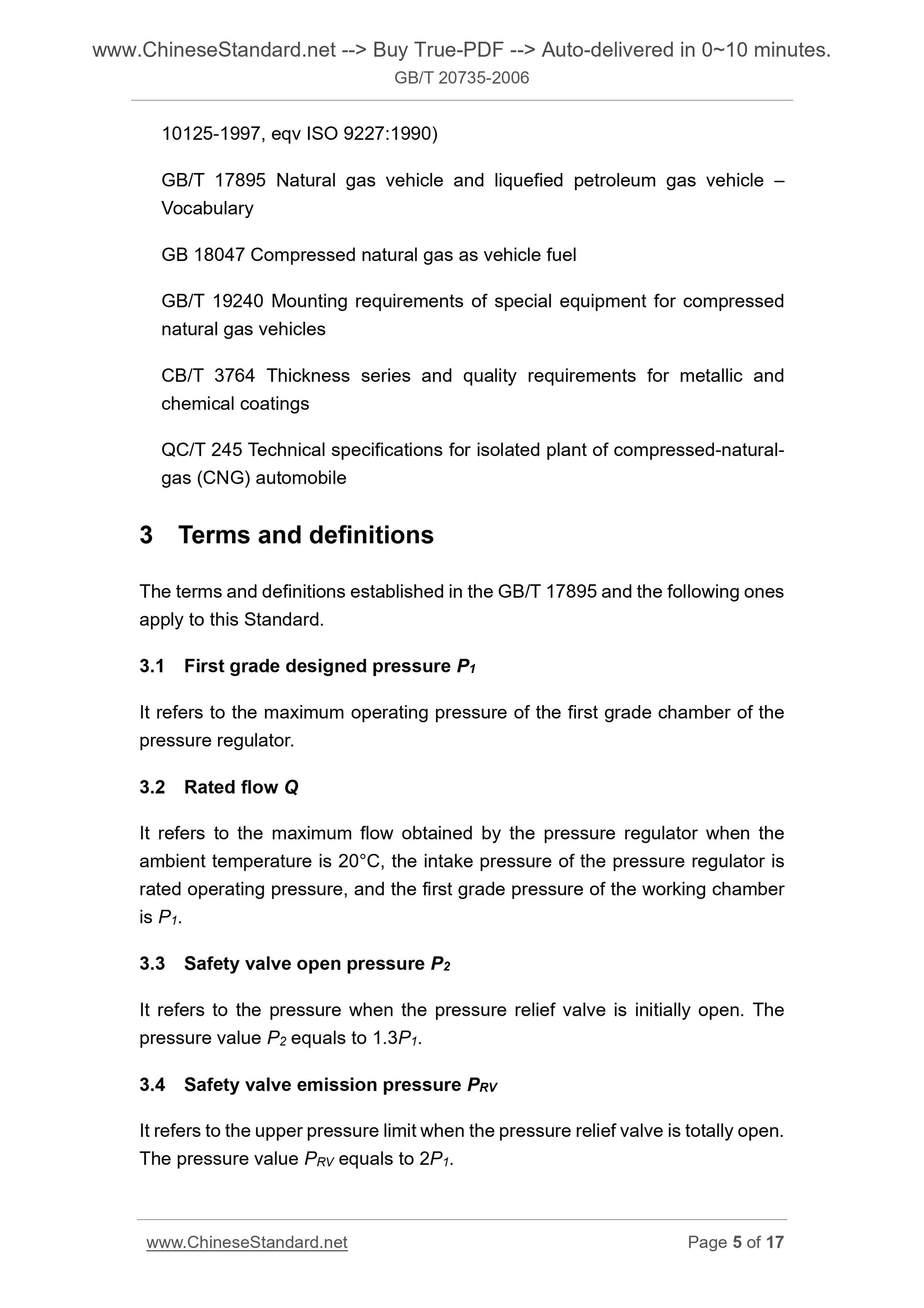
10125-1997, eqv ISO 9227.1990)
GB/T 17895 Natural gas vehicle and liquefied petroleum gas vehicle –
Vocabulary
GB 18047 Compressed natural gas as vehicle fuel
GB/T 19240 Mounting requirements of special equipment for compressed
natural gas vehicles
CB/T 3764 Thickness series and quality requirements for metallic and
chemical coatings
QC/T 245 Technical specifications for isolated plant of compressed-natural-
gas (CNG) automobile
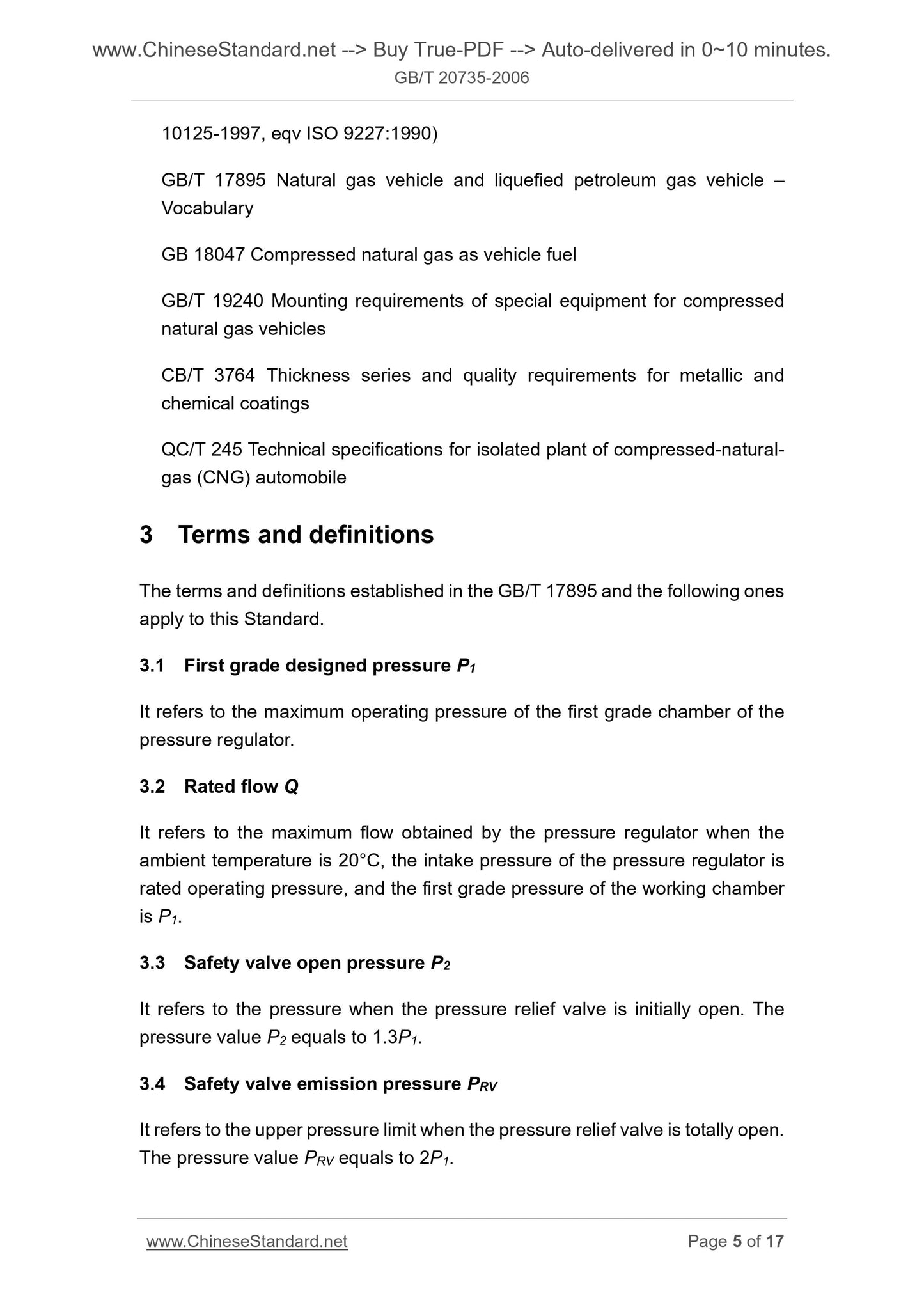
3 Terms and definitions
The terms and definitions established in the GB/T 17895 and the following ones
apply to this Standard.
3.1 First grade designed pressure P1
It refers to the maximum operating pressure of the first grade chamber of the
pressure regulator.
3.2 Rated flow Q
It refers to the maximum flow obtained by the pressure regulator when the
ambient temperature is 20°C, the intake pressure of the pressure regulator is
rated operating pressure, and the first grade pressure of the working chamber
is P1.
3.3 Safety valve open pressure P2
It refers to the pressure when the pressure relief valve is initially open. The
pressure value P2 equals to 1.3P1.
3.4 Safety valve emission pressure PRV
It refers to the upper pressure limit when the pressure relief valve is totally open.
The pressure value PRV equals to 2P1.
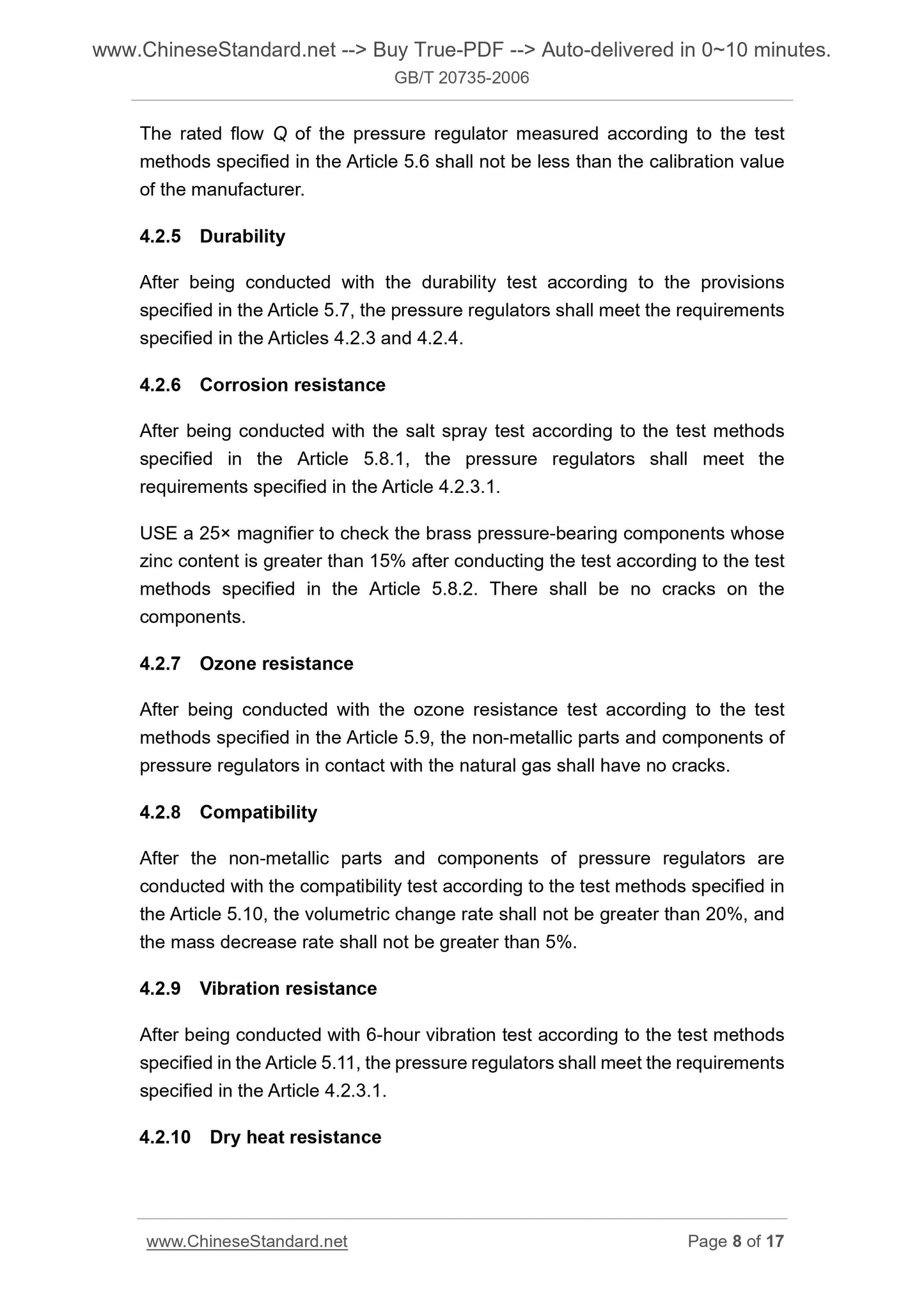
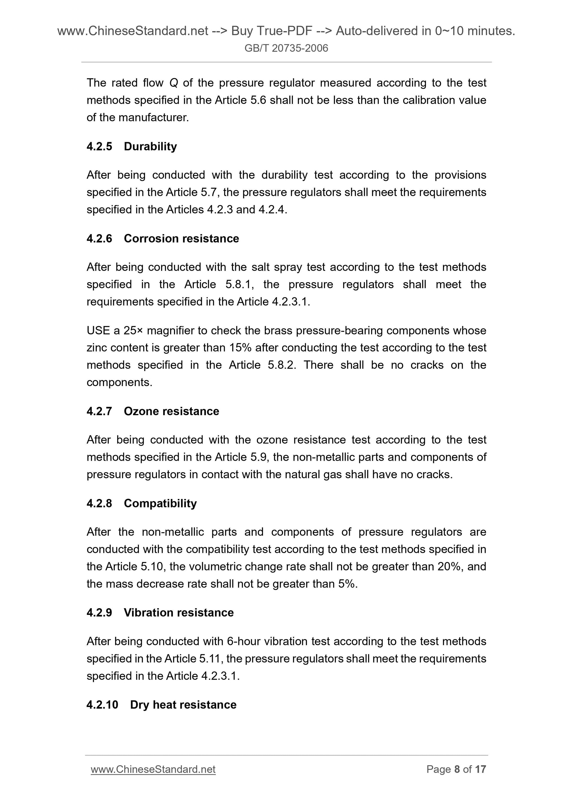
The rated flow Q of the pressure regulator measured according to the test
methods specified in the Article 5.6 shall not be less than the calibration value
of the manufacturer.
4.2.5 Durability
After being conducted with the durability test according to the provisions
specified in the Article 5.7, the pressure regulators shall meet the requirements
specified in the Articles 4.2.3 and 4.2.4.
4.2.6 Corrosion resistance
After being conducted with the salt spray test according to the test methods
specified in the Article 5.8.1, the pressure regulators shall meet the
requirements specified in the Article 4.2.3.1.
USE a 25× magnifier to check the brass pressure-bearing components whose
zinc content is greater than 15% after conducting the test according to the test
methods specified in the Article 5.8.2. There shall be no cracks on the
components.
4.2.7 Ozone resistance
After being conducted with the ozone resistance test according to the test
methods specified in the Article 5.9, the non-metallic parts and components of
pressure regulators in contact with the natural gas shall have no cracks.
4.2.8 Compatibility
After the non-metallic parts and components of pressure regulators are
conducted with the compatibility test according to the test methods specified in
the Article 5.10, the volumetric change rate shall not be greater than 20%, and
the mass decrease rate shall not be greater than 5%.
4.2.9 Vibration resistance
After being conducted with 6-hour vibration test according to the test methods
specified in the Article 5.11, the pressure regulators shall meet the requirements
specified in the Article 4.2.3.1.
4.2.10 Dry heat resistance
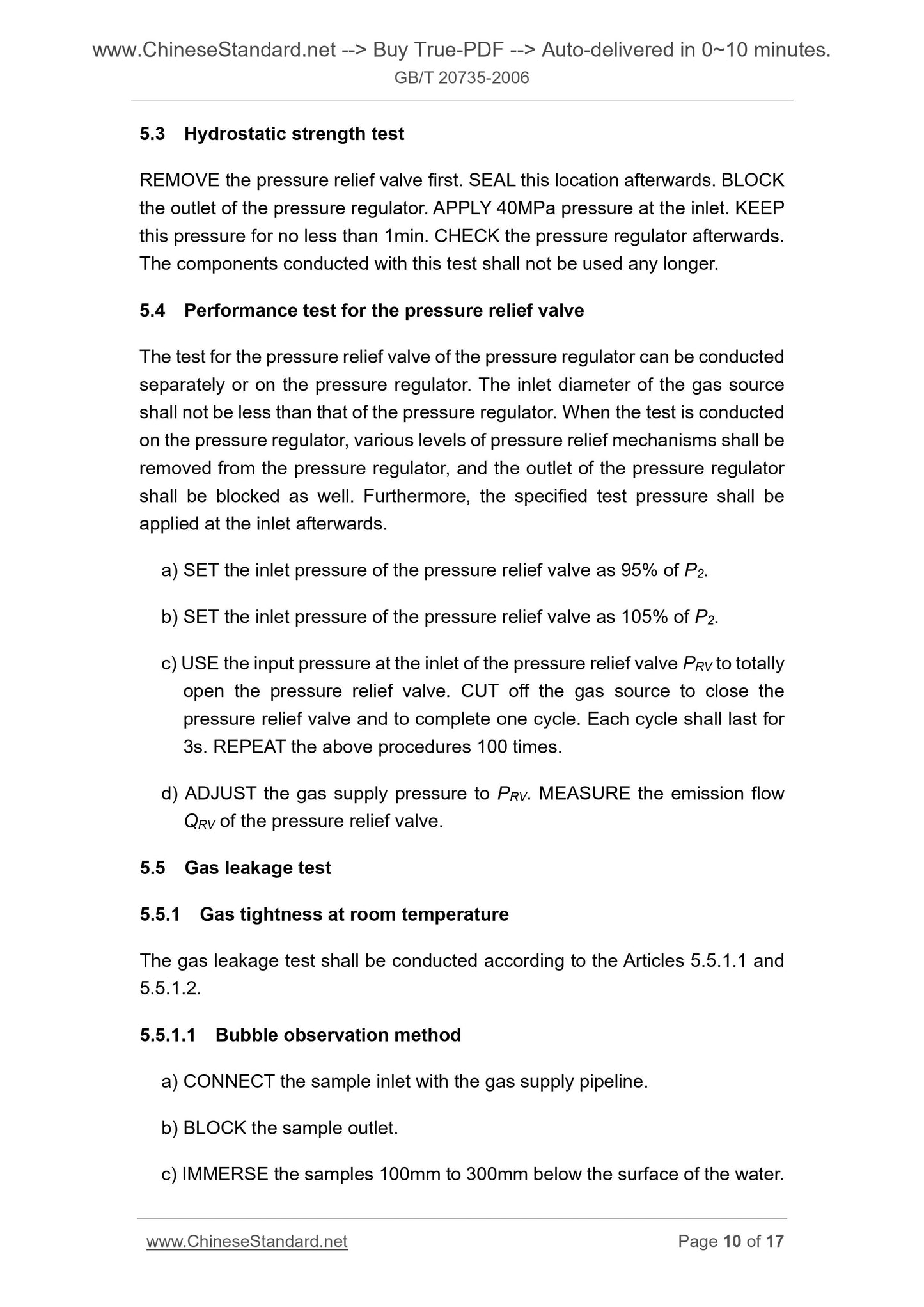
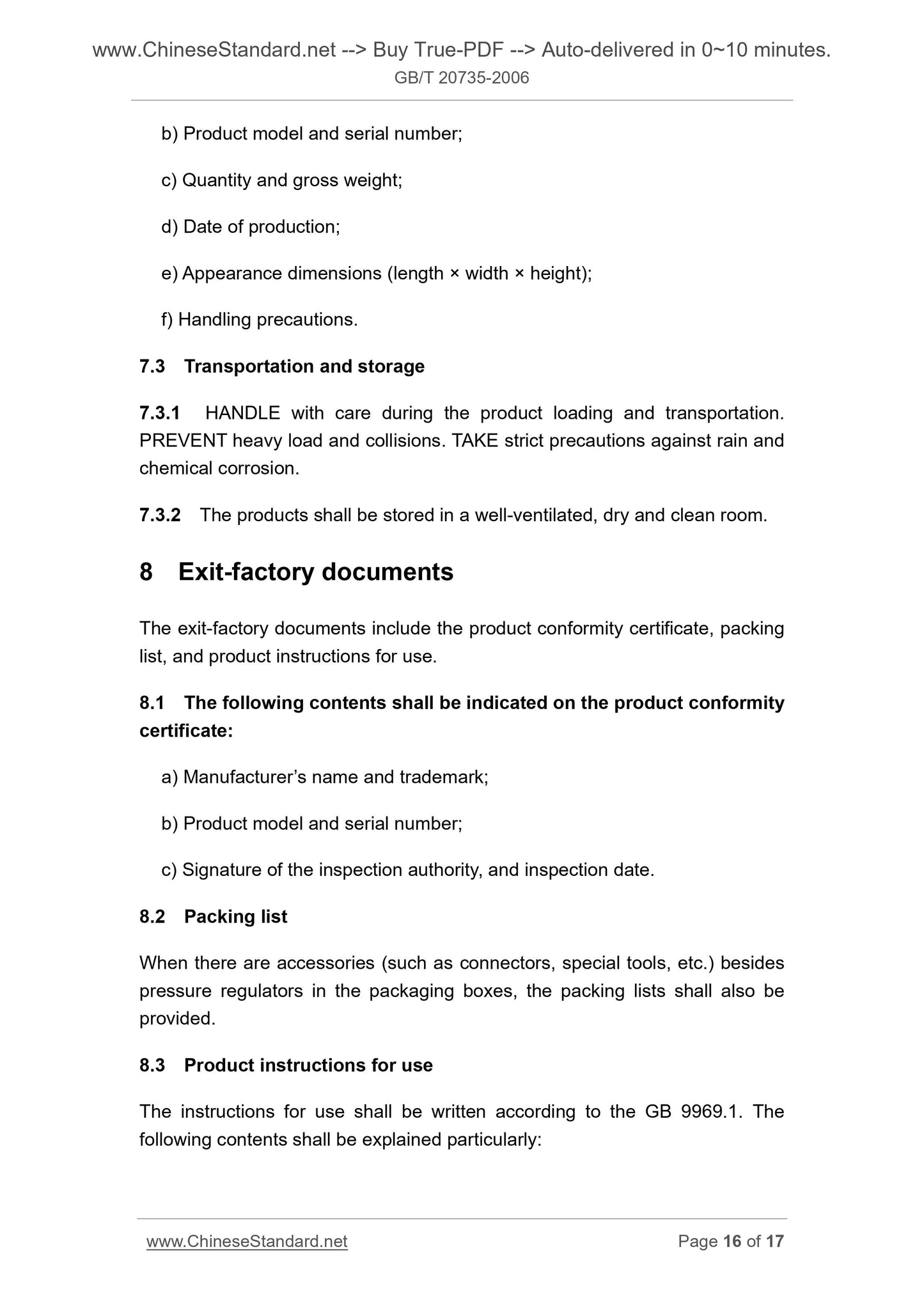
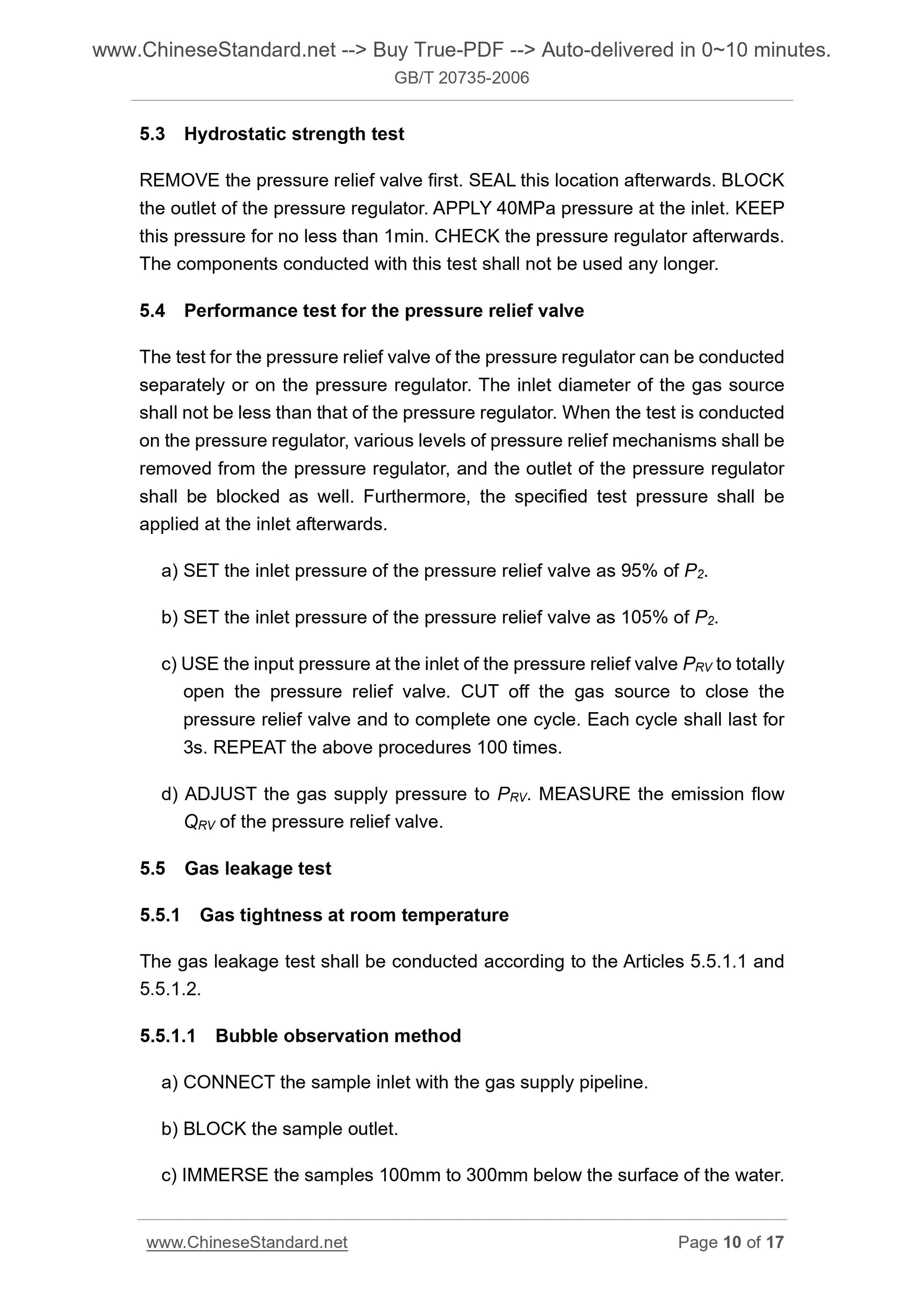
5.3 Hydrostatic strength test
REMOVE the pressure relief valve first. SEAL this location afterwards. BLOCK
the outlet of the pressure regulator. APPLY 40MPa pressure at the inlet. KEEP
this pressure for no less than 1min. CHECK the pressure regulator afterwards.
The components conducted with this test shall not be used any longer.
5.4 Performance test for the pressure relief valve
The test for the pressure relief valve of the pressure regulator can be conducted
separately or on the pressure regulator. The inlet diameter of the gas source
shall not be less than that of the pressure regulator. When the test is conducted
on the pressure regulator, various levels of pressure relief mechanisms shall be
removed from the pressure regulator, and the outlet of the pressure regulator
shall be blocked as well. Furthermore, the specified test pressure shall be
applied at the inlet afterwards.
a) SET the inlet pressure of the pressure relief valve as 95% of P2.
b) SET the inlet pressure of the pressure relief valve as 105% of P2.
c) USE the input pressure at the inlet of the pressure relief valve PRV to totally
open the pressure relief valve. CUT off the gas source to close the
pressure relief valve and to complete one cycle. Each cycle shall last for
3s. REPEAT the above procedures 100 times.
d) ADJUST the gas supply pressure to PRV. MEASURE the emission flow
QRV of the pressure relief valve.
5.5 Gas leakage test
5.5.1 Gas tightness at room temperature
The gas leakage test shall be conducted according to the Articles 5.5.1.1 and
5.5.1.2.
5.5.1.1 Bubble observation method
a) CONNECT the sample inlet with the gas supply pipeline.
b) BLOCK the sample outlet.
c) IMMERSE the samples 100mm to 300mm below the surface of the water.
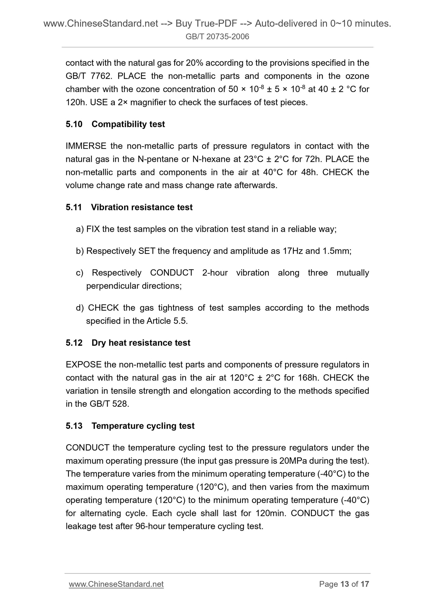
contact with the natural gas for 20% according to the provisions specified in the
GB/T 7762. PLACE the non-metallic parts and components in the ozone
chamber with the ozone concentration of 50 × 10-8 ± 5 × 10⁻⁸ at 40 ± 2 °C for
120h. USE a 2× magnifier to check the surfaces of test pieces.
5.10 Compatibility test
IMMERSE the non-metallic parts of pressure regulators in contact with the
natural gas in the N-pentane or N-hexane at 23°C ± 2°C for 72h. PLACE the
non-metallic parts and components in the air at 40°C for 48h. CHECK the
volume change rate and mass change rate afterwards.
5.11 Vibration resistance test
a) FIX the test samples on the vibration test stand in a reliable way;
b) Respectively SET the frequency and amplitude as 17Hz and 1.5mm;
c) Respectively CONDUCT 2-hour vibration along three mutually
perpendicular directions;
d) CHECK the gas tightness of test samples according to the methods
specified in the Article 5.5.
5.12 Dry heat resistance test
EXPOSE the non-metallic test parts and components of pressure regulators in
contact with the natural gas in the air at 120°C ± 2°C for 168h. CHECK the
variation in tensile strength and elongation according to the methods specified
in the GB/T 528.
5.13 Temperature cycling test
CONDUCT the temperature cycling test to the pressure regulators under the
maximum operating pressure (the input gas pressure is 20MPa during the test).
The temperature varies from the minimum operating temperature (-40°C) to the
maximum operating temperature (120°C), and then...
GB/T 20735-2006
GB
ICS 43.080
T 47
National Standard
of the People’s Republic of China
Pressure regulator of CNG vehicles
ISSUED ON. DECEMBER 29, 2006
IMPLEMENTED ON. JUNE 1, 2007
Issued by. General Administration of Quality Supervision, Inspection and
Quarantine of the People’s Republic of China;
Standardization Administration of the People’s Republic of
China.
Table of Contents
Foreword ... 3
1 Scope ... 4
2 Normative references ... 4
3 Terms and definitions ... 5
4 Requirements ... 6
5 Test methods ... 9
6 Inspection rules ... 14
7 Marks, packaging, transportation and storage ... 15
8 Exit-factory documents ... 16
Foreword
This Standard was proposed by and shall be under the jurisdiction of the
National Technical Committee for Standardization of Automobiles.
Drafting organizations of this Standard. Chongqing Automobile Research
Institute, and Chongqing Dinghui Automobile Fuel Gas System Co., Ltd.
Main drafters of this Standard. Chen Wanying, Zhang Haihui, Liu Jun, and
Wang Shu.
Pressure regulator of CNG vehicles
1 Scope
This Standard specifies the model label, requirements, test methods, inspection
rules, marks, packaging, transportation and storage of the pressure regulator
of compressed natural gas (hereinafter referred to as CNG) vehicles.
This Standard applies to the pressure regulators of CNG vehicles (hereinafter
referred to as pressure regulators) whose nominal operating pressure is not
more than 20MPa (the pressure described in this Standard refers to gage
pressure), whose operating ambient temperature is within the range of -40°C ~
120°C, and whose working medium meets the requirements specified in the GB
18047.
2 Normative references
The provisions in the following documents become the provisions of this
Standard through reference in this Standard. For dated references, the
subsequent amendments (excluding corrections) or revisions do not apply to
this Standard. However, parties who reach an agreement based on this
Standard are encouraged to study if the latest versions of these documents are
applicable. For undated references, the latest versions apply to this Standard.
GB/T 528 Rubber, vulcanized or thermoplastic – Determination of tensile
stress-strain properties (GB/T 528-1998, eqv ISO 37.1994)
GB/T 3765 24° cone connectors – Specification
GB/T 7762 Rubber, vulcanized or thermoplastic – Resistance to ozone
cracking – Static strain test (GB/T 7762-2003, ISO 1431-1.1989 Rubber,
vulcanized or thermoplastic – Resistance to ozone cracking – Part 1. Static
and dynamic strain testing, MOD)
GB 9969.1 General principles for preparation of instructions for use of
industrial products
GB/T 10125 Corrosion tests in artificial atmospheres – Salt spray tests (GB/T
10125-1997, eqv ISO 9227.1990)
GB/T 17895 Natural gas vehicle and liquefied petroleum gas vehicle –
Vocabulary
GB 18047 Compressed natural gas as vehicle fuel
GB/T 19240 Mounting requirements of special equipment for compressed
natural gas vehicles
CB/T 3764 Thickness series and quality requirements for metallic and
chemical coatings
QC/T 245 Technical specifications for isolated plant of compressed-natural-
gas (CNG) automobile
3 Terms and definitions
The terms and definitions established in the GB/T 17895 and the following ones
apply to this Standard.
3.1 First grade designed pressure P1
It refers to the maximum operating pressure of the first grade chamber of the
pressure regulator.
3.2 Rated flow Q
It refers to the maximum flow obtained by the pressure regulator when the
ambient temperature is 20°C, the intake pressure of the pressure regulator is
rated operating pressure, and the first grade pressure of the working chamber
is P1.
3.3 Safety valve open pressure P2
It refers to the pressure when the pressure relief valve is initially open. The
pressure value P2 equals to 1.3P1.
3.4 Safety valve emission pressure PRV
It refers to the upper pressure limit when the pressure relief valve is totally open.
The pressure value PRV equals to 2P1.
The rated flow Q of the pressure regulator measured according to the test
methods specified in the Article 5.6 shall not be less than the calibration value
of the manufacturer.
4.2.5 Durability
After being conducted with the durability test according to the provisions
specified in the Article 5.7, the pressure regulators shall meet the requirements
specified in the Articles 4.2.3 and 4.2.4.
4.2.6 Corrosion resistance
After being conducted with the salt spray test according to the test methods
specified in the Article 5.8.1, the pressure regulators shall meet the
requirements specified in the Article 4.2.3.1.
USE a 25× magnifier to check the brass pressure-bearing components whose
zinc content is greater than 15% after conducting the test according to the tes...
Share