GB/T 20368-2021 English PDF (GBT20368-2021)
Regular price
$905.00 USD
Regular price
Sale price
$905.00 USD
Unit price
/
per
Delivery: 3 seconds. Download true-PDF + Invoice.
Get QUOTATION in 1-minute: Click GB/T 20368-2021
Historical versions: GB/T 20368-2021
Preview True-PDF (Reload/Scroll if blank)
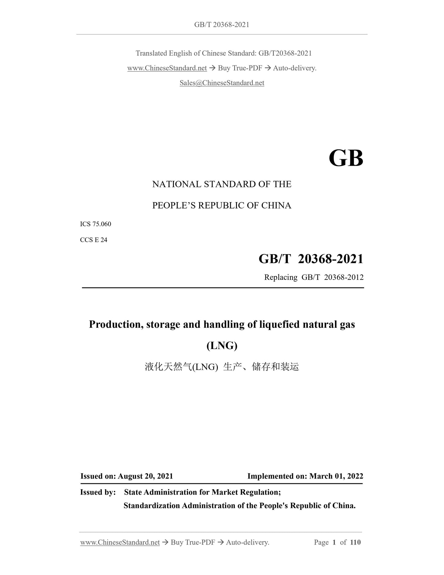
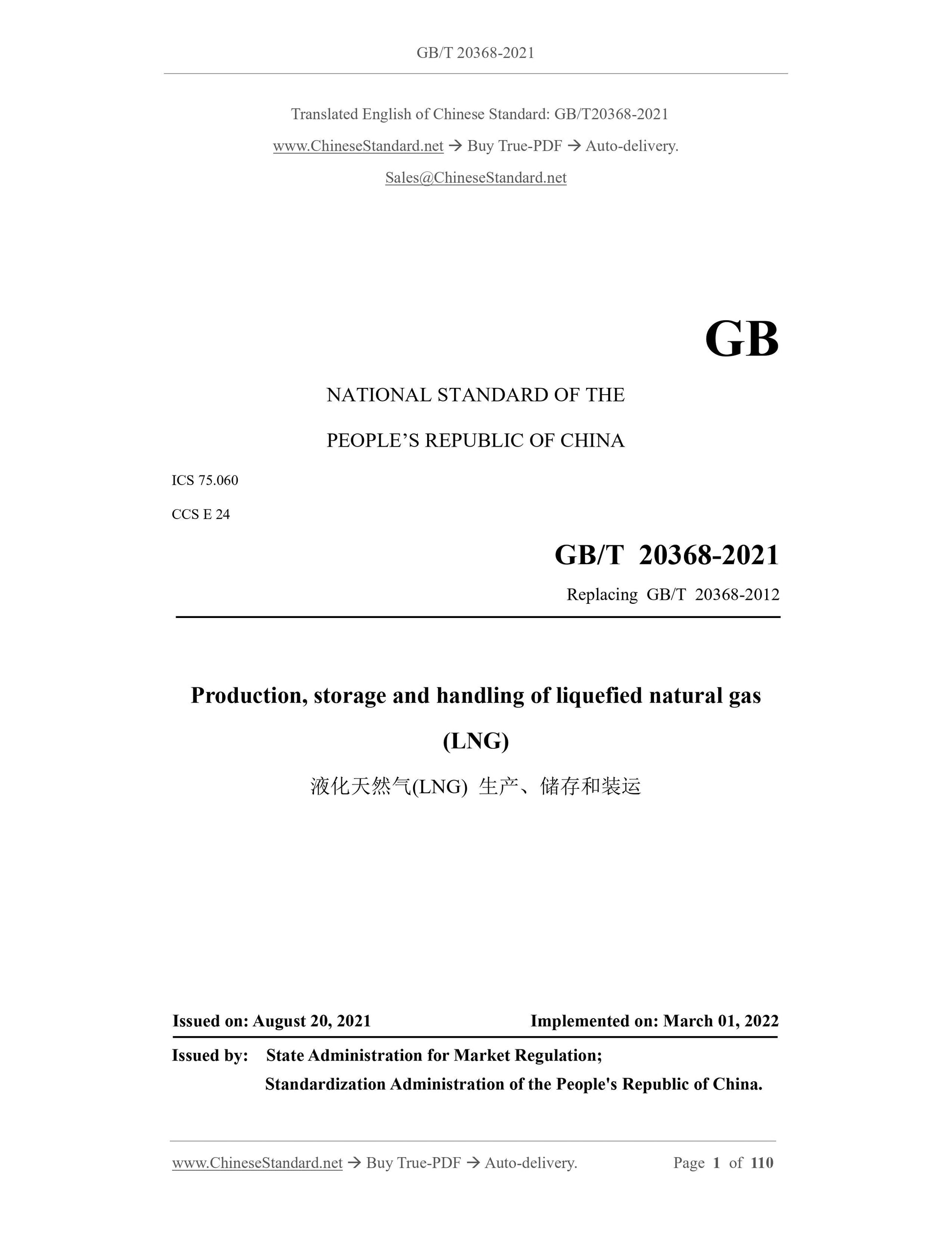
GB/T 20368-2021: Production, storage and handling of liquefied natural gas(LNG)
GB/T 20368-2021
GB
NATIONAL STANDARD OF THE
PEOPLE’S REPUBLIC OF CHINA
ICS 75.060
CCS E 24
Replacing GB/T 20368-2012
Production, storage and handling of liquefied natural gas
(LNG)
ISSUED ON: AUGUST 20, 2021
IMPLEMENTED ON: MARCH 01, 2022
Issued by: State Administration for Market Regulation;
Standardization Administration of the People's Republic of China.
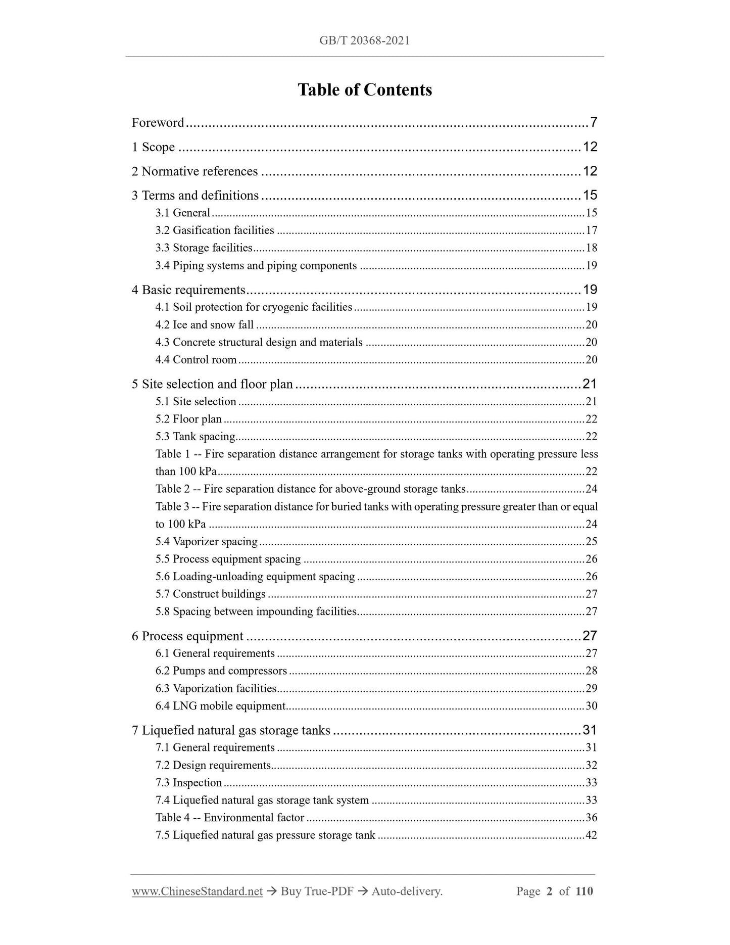
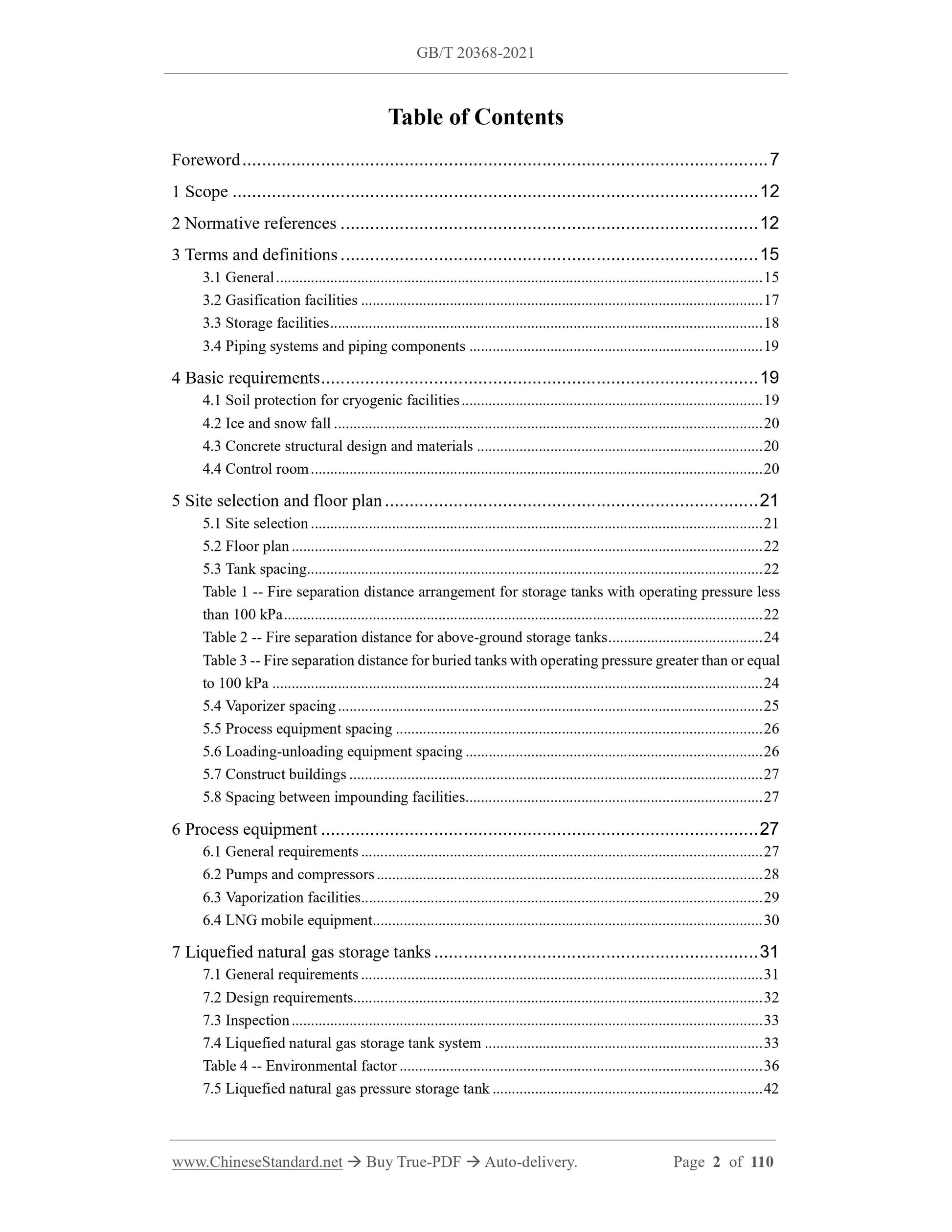
Table of Contents
Foreword ... 7
1 Scope ... 12
2 Normative references ... 12
3 Terms and definitions ... 15
3.1 General ... 15
3.2 Gasification facilities ... 17
3.3 Storage facilities ... 18
3.4 Piping systems and piping components ... 19
4 Basic requirements ... 19
4.1 Soil protection for cryogenic facilities ... 19
4.2 Ice and snow fall ... 20
4.3 Concrete structural design and materials ... 20
4.4 Control room ... 20
5 Site selection and floor plan ... 21
5.1 Site selection ... 21
5.2 Floor plan ... 22
5.3 Tank spacing ... 22
Table 1 -- Fire separation distance arrangement for storage tanks with operating pressure less
than 100 kPa ... 22
Table 2 -- Fire separation distance for above-ground storage tanks ... 24
Table 3 -- Fire separation distance for buried tanks with operating pressure greater than or equal
to 100 kPa ... 24
5.4 Vaporizer spacing ... 25
5.5 Process equipment spacing ... 26
5.6 Loading-unloading equipment spacing ... 26
5.7 Construct buildings ... 27
5.8 Spacing between impounding facilities ... 27
6 Process equipment ... 27
6.1 General requirements ... 27
6.2 Pumps and compressors ... 28
6.3 Vaporization facilities ... 29
6.4 LNG mobile equipment ... 30
7 Liquefied natural gas storage tanks ... 31
7.1 General requirements ... 31
7.2 Design requirements... 32
7.3 Inspection ... 33
7.4 Liquefied natural gas storage tank system ... 33
Table 4 -- Environmental factor ... 36
7.5 Liquefied natural gas pressure storage tank ... 42
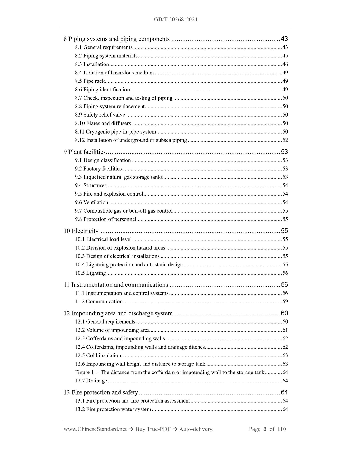
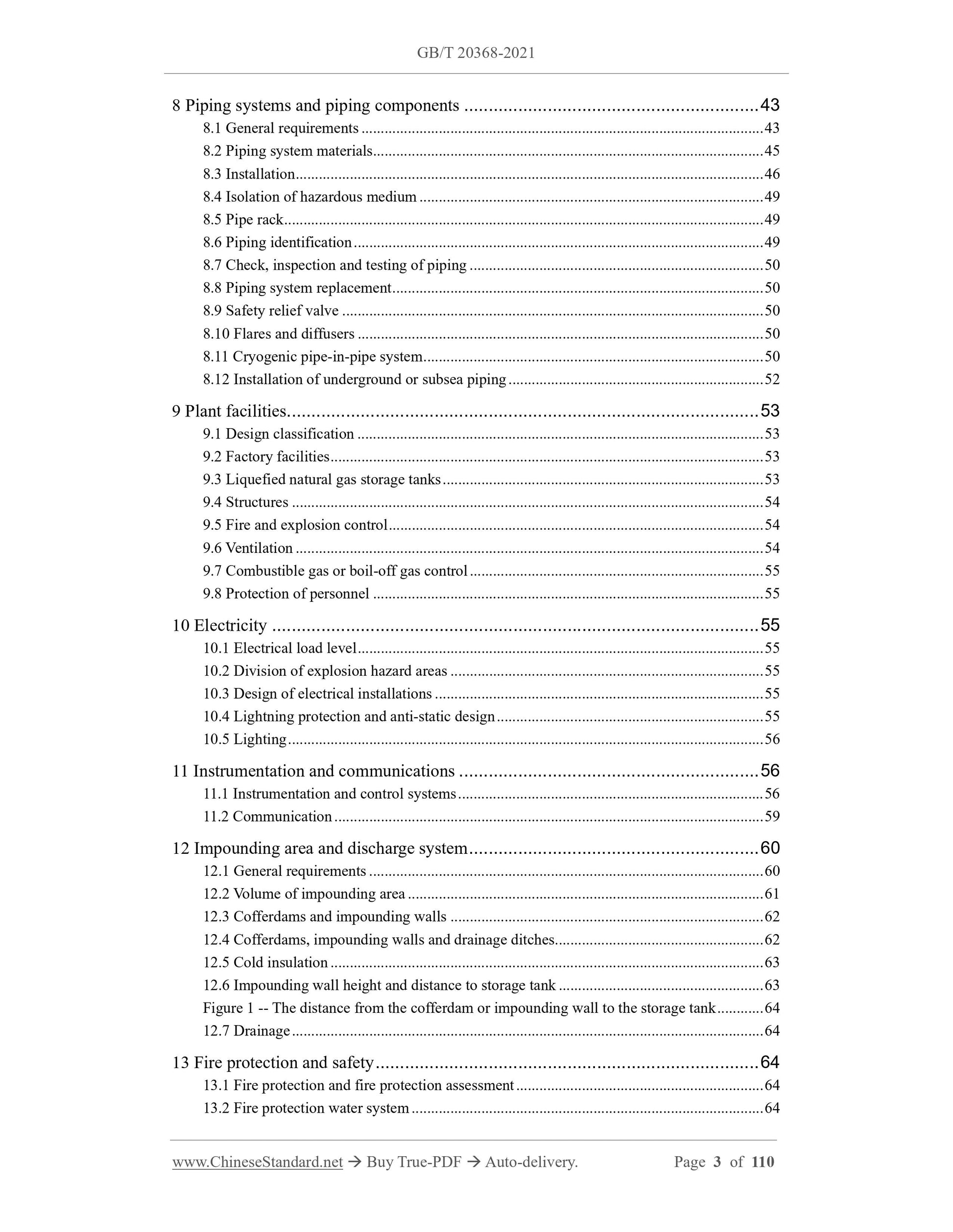
8 Piping systems and piping components ... 43
8.1 General requirements ... 43
8.2 Piping system materials ... 45
8.3 Installation ... 46
8.4 Isolation of hazardous medium ... 49
8.5 Pipe rack ... 49
8.6 Piping identification ... 49
8.7 Check, inspection and testing of piping ... 50
8.8 Piping system replacement ... 50
8.9 Safety relief valve ... 50
8.10 Flares and diffusers ... 50
8.11 Cryogenic pipe-in-pipe system ... 50
8.12 Installation of underground or subsea piping ... 52
9 Plant facilities ... 53
9.1 Design classification ... 53
9.2 Factory facilities ... 53
9.3 Liquefied natural gas storage tanks ... 53
9.4 Structures ... 54
9.5 Fire and explosion control ... 54
9.6 Ventilation ... 54
9.7 Combustible gas or boil-off gas control ... 55
9.8 Protection of personnel ... 55
10 Electricity ... 55
10.1 Electrical load level ... 55
10.2 Division of explosion hazard areas ... 55
10.3 Design of electrical installations ... 55
10.4 Lightning protection and anti-static design ... 55
10.5 Lighting ... 56
11 Instrumentation and communications ... 56
11.1 Instrumentation and control systems ... 56
11.2 Communication ... 59
12 Impounding area and discharge system ... 60
12.1 General requirements ... 60
12.2 Volume of impounding area ... 61
12.3 Cofferdams and impounding walls ... 62
12.4 Cofferdams, impounding walls and drainage ditches ... 62
12.5 Cold insulation ... 63
12.6 Impounding wall height and distance to storage tank ... 63
Figure 1 -- The distance from the cofferdam or impounding wall to the storage tank ... 64
12.7 Drainage ... 64
13 Fire protection and safety ... 64
13.1 Fire protection and fire protection assessment ... 64
13.2 Fire protection water system ... 64
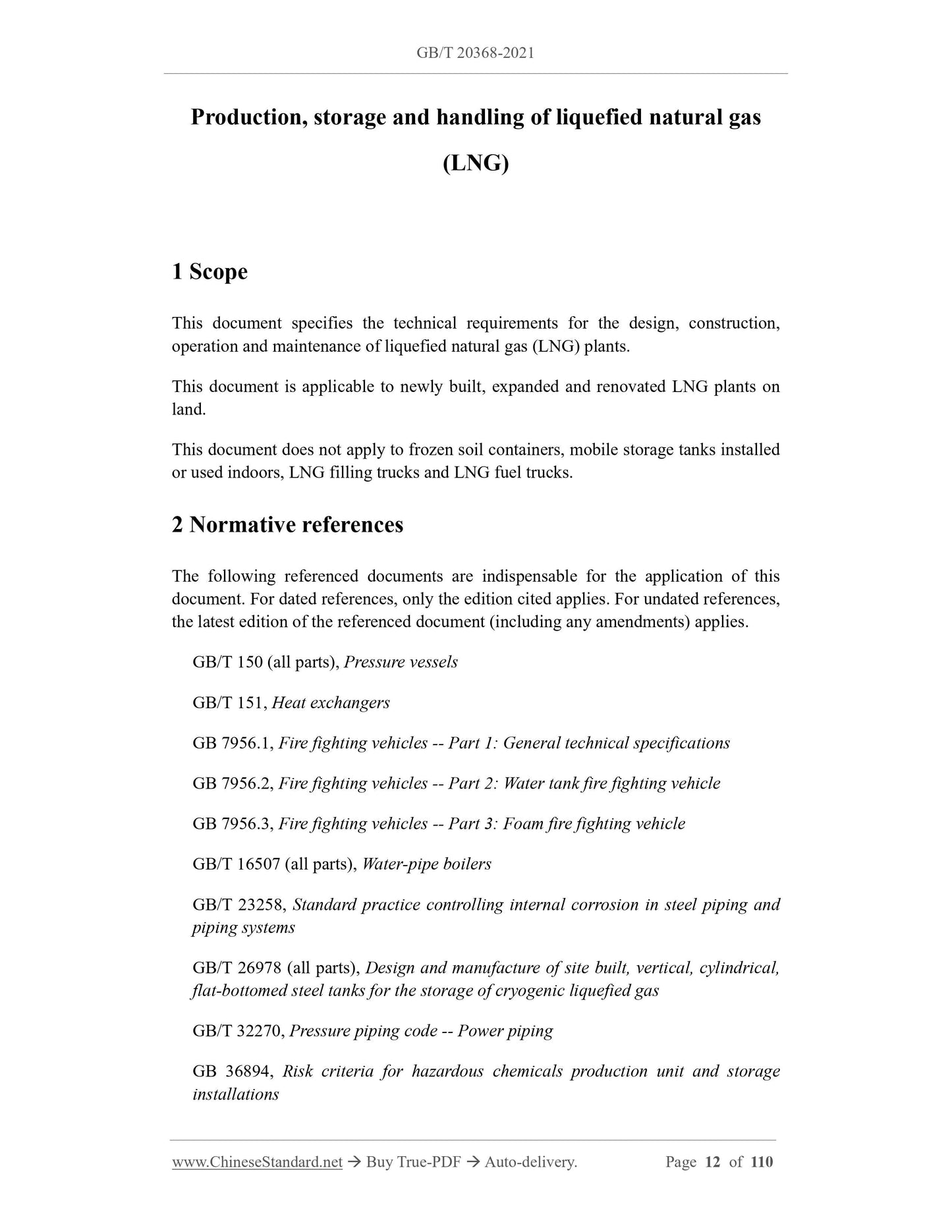
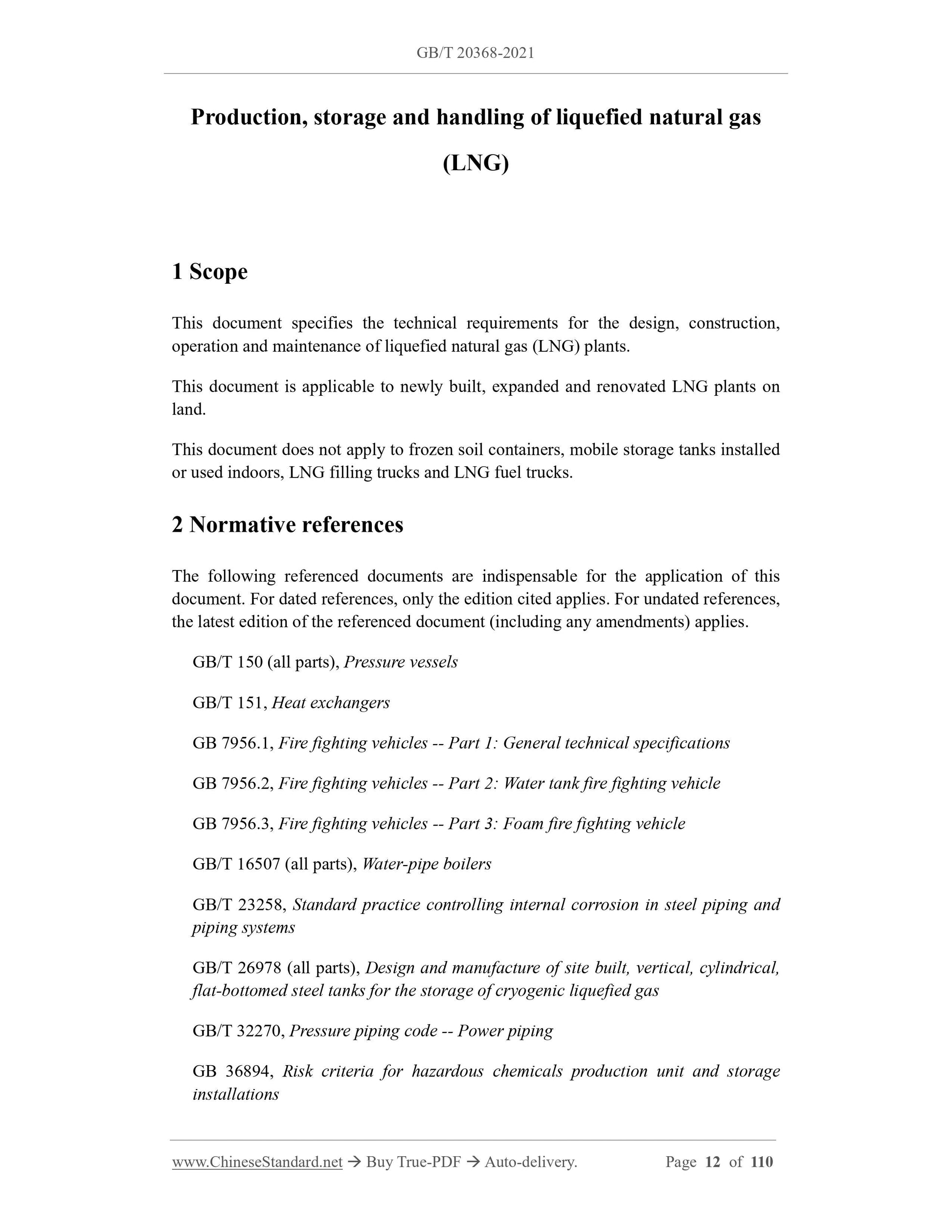
Production, storage and handling of liquefied natural gas
(LNG)
1 Scope
This document specifies the technical requirements for the design, construction,
operation and maintenance of liquefied natural gas (LNG) plants.
This document is applicable to newly built, expanded and renovated LNG plants on
land.
This document does not apply to frozen soil containers, mobile storage tanks installed
or used indoors, LNG filling trucks and LNG fuel trucks.
2 Normative references
The following referenced documents are indispensable for the application of this
document. For dated references, only the edition cited applies. For undated references,
the latest edition of the referenced document (including any amendments) applies.
GB/T 150 (all parts), Pressure vessels
GB/T 151, Heat exchangers
GB 7956.1, Fire fighting vehicles -- Part 1: General technical specifications
GB 7956.2, Fire fighting vehicles -- Part 2: Water tank fire fighting vehicle
GB 7956.3, Fire fighting vehicles -- Part 3: Foam fire fighting vehicle
GB/T 16507 (all parts), Water-pipe boilers
GB/T 23258, Standard practice controlling internal corrosion in steel piping and
piping systems
GB/T 26978 (all parts), Design and manufacture of site built, vertical, cylindrical,
flat-bottomed steel tanks for the storage of cryogenic liquefied gas
GB/T 32270, Pressure piping code -- Power piping
GB 36894, Risk criteria for hazardous chemicals production unit and storage
installations
heat or limit surface temperature;
4) Analysis of LNG storage tank materials, design, and construction methods.
5.3.4 If there are no fire protection measures, the concrete outer tank shall be designed
to prevent external fire. Conduct thermal analysis to determine temperature distribution
and fire action time:
a) For membrane tank systems, the fire protection design shall include the
hydrostatic pressure of the stored liquid at the design level. When designing fire
protection for all types of storage tanks, it shall be assumed that the internal gas
is at positive pressure;
b) The design of concrete outer tanks shall consider the following factors:
1) In case of fire, there is a difference in thermal expansion coefficient between
prestressed steel bars and tank wall concrete at high temperatures, resulting in
a reduction in the effective prestress of the tank wall;
2) As the temperature of the outer concrete tank increases, the strength and elastic
modulus of the concrete, steel bars and prestressed steel bars in the outer tank
decrease;
3) Due to the softening and relaxation of prestressed steel bars at high
temperatures, the effective prestress of the tank wall is reduced.
5.3.5 Multiple tank shut-off valves shall have at least 0.9 m of operating space.
5.3.6 LNG storage tanks larger than 0.5 m3 shall not be built indoors.
5.3.7 Flammable liquid and flammable refrigerant storage tanks shall not be arranged
in the LNG storage tank impounding area specified in Chapter 12.
5.4 Vaporizer spacing
5.4.1 In addition to the provisions of 5.4.5, the distance between the vaporizer and the
plant fence shall not be less than 30 m.
5.4.2 The distance between adjacent vaporizers shall not be less than 1.5 m.
5.4.3 When a vaporizer using flammable medium as the heat source, the distance
between its primary heat source and any ignition source shall not be less than 15 m,
except in the following circumstances:
a) When two or more vaporizers are arranged in the same area, adjacent vaporizers
or primary heat sources do not need to be considered as sources of ignition;
b) When the vaporizer is interlocked with a process heater or other open flame
equipment, the vaporizer cannot be operated due to the interlock when the
vaporiz...