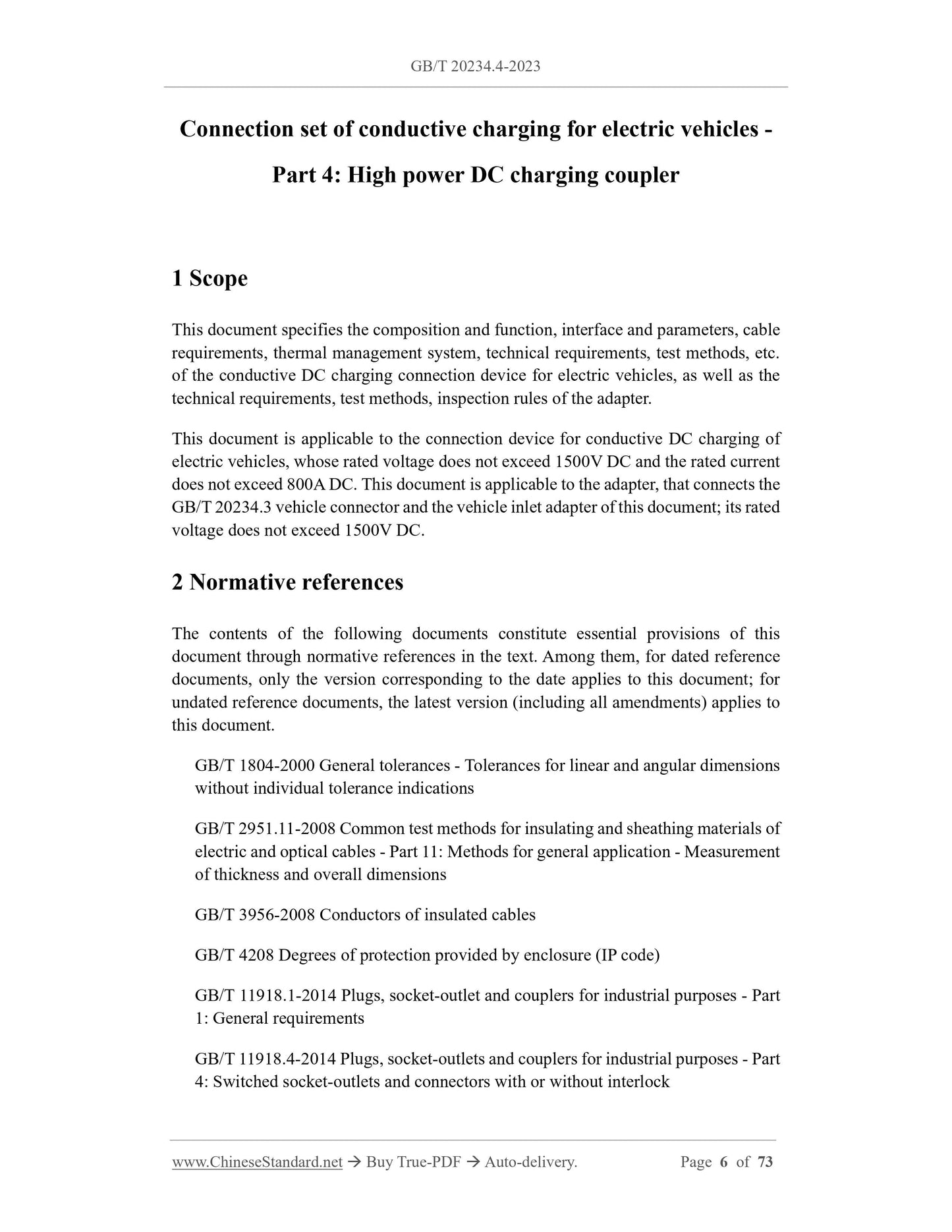
This document specifies the composition and function, interface and parameters, cable requirements, thermal management system, technical requirements, test methods, etc. of the conductive DC charging connection device for electric vehicles, as well as the technical requirements, test methods, inspection rules of the adapter. This document is applicable to the connection device for conductive DC charging of electric vehicles, whose rated voltage does not exceed 1500V DC and the rated current does not exceed 800A DC. This document is applicable to the adapter, that connects the GB/T 20234.3 vehicle connector and the vehicle inlet adapter of this document; its rated voltage does not exceed 1500V DC.
Basic Data
Standard ID
GB/T 20234.4-2023 (GB/T20234.4-2023)
Description (Translated English)
Connection set for conductive charging of electric vehicles - Part 4: High power DC charging coupler
Sector / Industry
National Standard (Recommended)
Classification of Chinese Standard
T35
Classification of International Standard
43.040.99
Word Count Estimation
54,564
Date of Issue
2023-09-07
Date of Implementation
2024-04-01
Issuing agency(ies)
State Administration for Market Regulation, China National Standardization Administration