GB/T 20234.2-2011 English PDF (GBT20234.2-2011)
Regular price
$70.00 USD
Regular price
Sale price
$70.00 USD
Unit price
/
per
Delivery: 3 seconds. Download true-PDF + Invoice.Newer version: (Replacing this standard) GB/T 20234.2-2015
Get QUOTATION in 1-minute: Click GB/T 20234.2-2011
Historical versions: GB/T 20234.2-2011
Preview True-PDF (Reload/Scroll if blank)
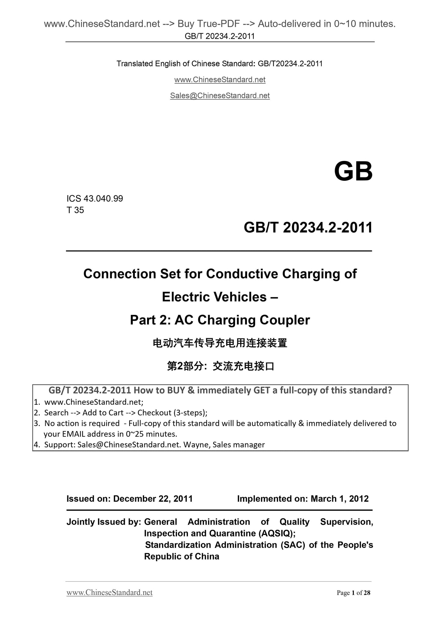
GB/T 20234.2-2011: Connection set for conductive charging of electric vehicles -- Part 2: AC charging coupler
GB/T 20234.2-2011
GB
ICS 43.040.99
T 35
Connection Set for Conductive Charging of
Electric Vehicles –
Part 2. AC Charging Coupler
ISSUED ON. DECEMBER 22, 2011
IMPLEMENTED ON. MARCH 1, 2012
Jointly Issued by. General Administration of Quality Supervision,
Inspection and Quarantine (AQSIQ);
Standardization Administration (SAC) of the People's
Republic of China
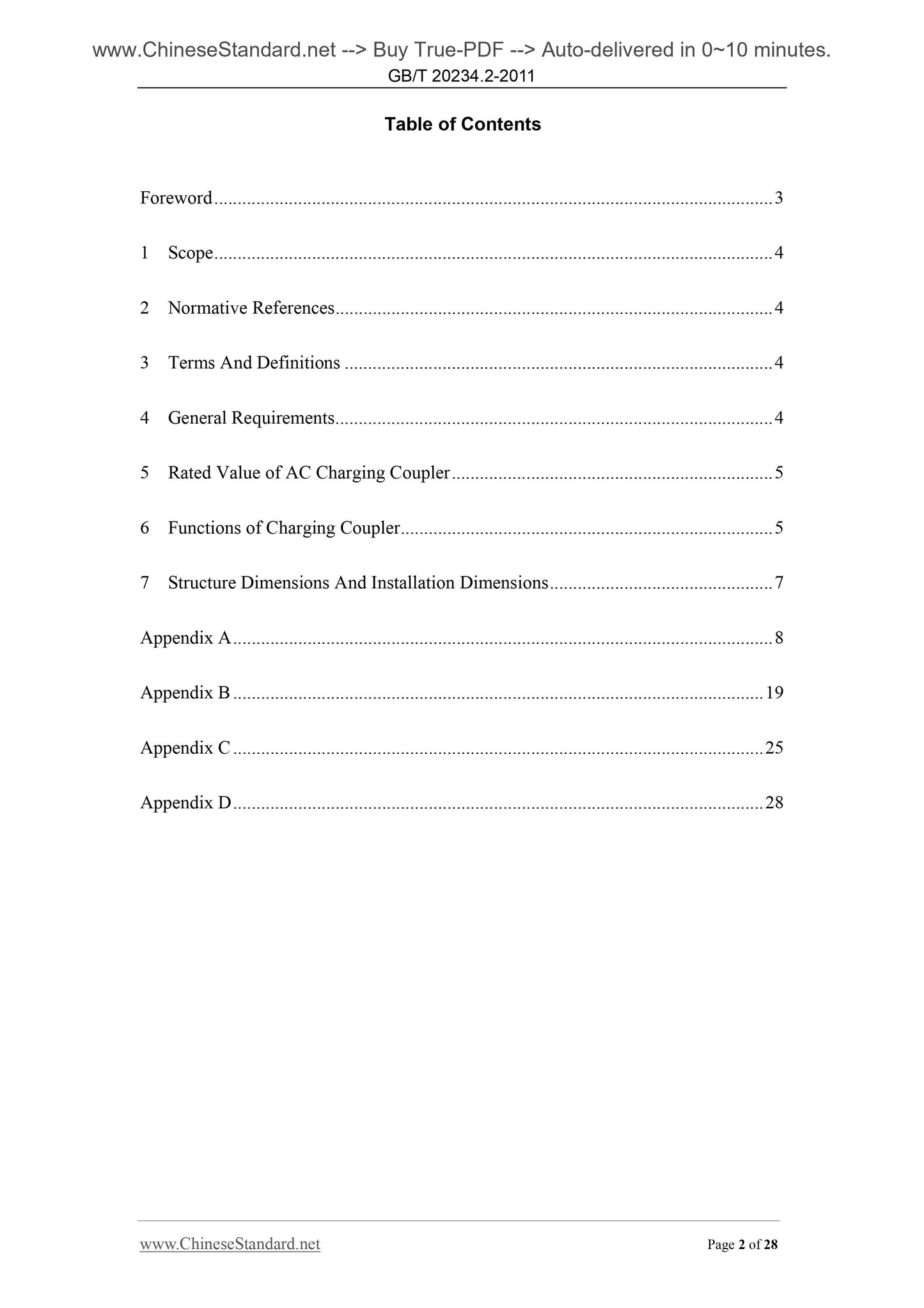
Table of Contents
Foreword ... 3
1 Scope ... 4
2 Normative References ... 4
3 Terms And Definitions ... 4
4 General Requirements ... 4
5 Rated Value of AC Charging Coupler ... 5
6 Functions of Charging Coupler ... 5
7 Structure Dimensions And Installation Dimensions ... 7
Appendix A ... 8
Appendix B ... 19
Appendix C ... 25
Appendix D ... 28
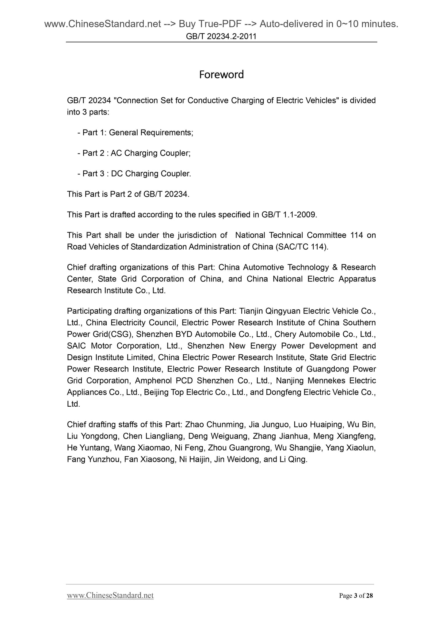
Foreword
GB/T 20234 "Connection Set for Conductive Charging of Electric Vehicles" is divided
into 3 parts.
- Part 1. General Requirements;
- Part 2 . AC Charging Coupler;
- Part 3 . DC Charging Coupler.
This Part is Part 2 of GB/T 20234.
This Part is drafted according to the rules specified in GB/T 1.1-2009.
This Part shall be under the jurisdiction of National Technical Committee 114 on
Road Vehicles of Standardization Administration of China (SAC/TC 114).
Chief drafting organizations of this Part. China Automotive Technology and Research
Center, State Grid Corporation of China, and China National Electric Apparatus
Research Institute Co., Ltd.
Participating drafting organizations of this Part. Tianjin Qingyuan Electric Vehicle Co.,
Ltd., China Electricity Council, Electric Power Research Institute of China Southern
Power Grid(CSG), Shenzhen BYD Automobile Co., Ltd., Chery Automobile Co., Ltd.,
SAIC Motor Corporation, Ltd., Shenzhen New Energy Power Development and
Design Institute Limited, China Electric Power Research Institute, State Grid Electric
Power Research Institute, Electric Power Research Institute of Guangdong Power
Grid Corporation, Amphenol PCD Shenzhen Co., Ltd., Nanjing Mennekes Electric
Appliances Co., Ltd., Beijing Top Electric Co., Ltd., and Dongfeng Electric Vehicle Co.,
Ltd.
Chief drafting staffs of this Part. Zhao Chunming, Jia Junguo, Luo Huaiping, Wu Bin,
Liu Yongdong, Chen Liangliang, Deng Weiguang, Zhang Jianhua, Meng Xiangfeng,
He Yuntang, Wang Xiaomao, Ni Feng, Zhou Guangrong, Wu Shangjie, Yang Xiaolun,
Fang Yunzhou, Fan Xiaosong, Ni Haijin, Jin Weidong, and Li Qing.
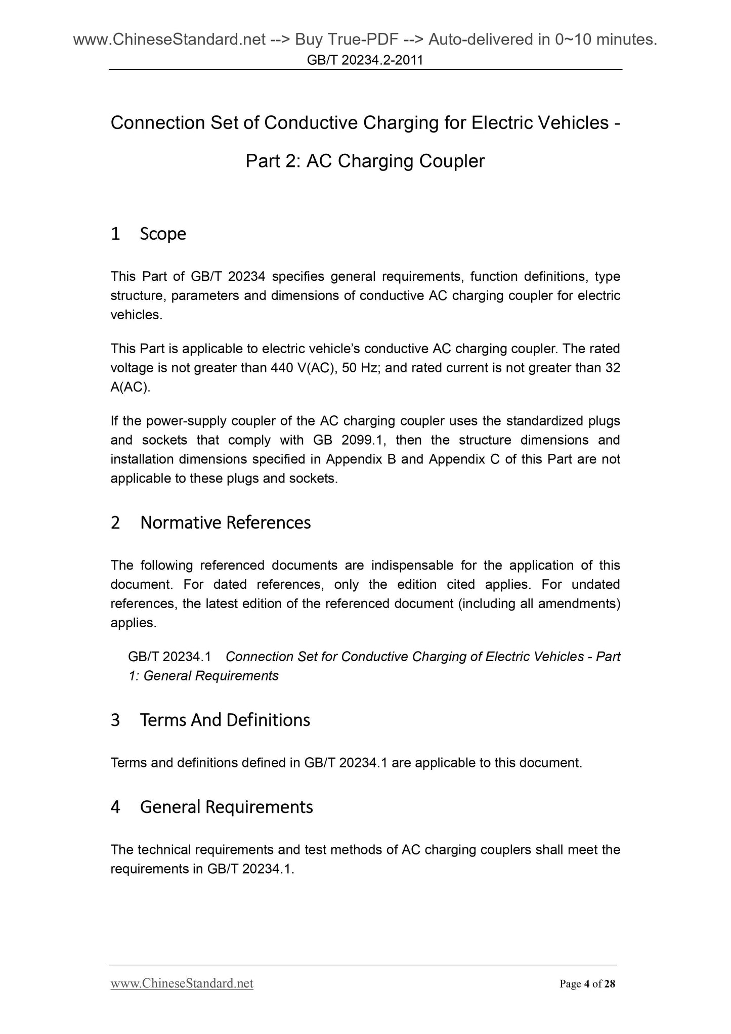
Connection Set of Conductive Charging for Electric Vehicles -
Part 2. AC Charging Coupler
1 Scope
This Part of GB/T 20234 specifies general requirements, function definitions, type
structure, parameters and dimensions of conductive AC charging coupler for electric
vehicles.
This Part is applicable to electric vehicle’s conductive AC charging coupler. The rated
voltage is not greater than 440 V(AC), 50 Hz; and rated current is not greater than 32
A(AC).
If the power-supply coupler of the AC charging coupler uses the standardized plugs
and sockets that comply with GB 2099.1, then the structure dimensions and
installation dimensions specified in Appendix B and Appendix C of this Part are not
applicable to these plugs and sockets.
2 Normative References
The following referenced documents are indispensable for the application of this
document. For dated references, only the edition cited applies. For undated
references, the latest edition of the referenced document (including all amendments)
applies.
GB/T 20234.1 Connection Set for Conductive Charging of Electric Vehicles - Part
1. General Requirements
3 Terms And Definitions
Terms and definitions defined in GB/T 20234.1 are applicable to this document.
4 General Requirements
The technical requirements and test methods of AC charging couplers shall meet the
requirements in GB/T 20234.1.
Appendix A
(Informative)
Control Pilot Circuit And Control Principles
A.1 Control pilot circuit
A.1.1 Charging Mode 3
It is recommended, when the electric vehicle is charged by adopting the charging
mode 3, to use the typical control pilot circuit as shown in Figure A.1 (connection
mode A), Figure A.2 (connection mode B) and Figure A.3 (connection mode C) to
perform the connection confirmation of the charging connection devices and the
judgment of the rated current parameters. The circuit consists of power-supply control
device, contactor K1 and contactor K2 (it may only set one), resistances R1, R2, R3
and RC, diode D1, Switches S1, S2 and S3, the on-board charger and vehicle control
devices which can be integrated into the on-board charger or on-board control units.
The recommended parameter of the control pilot circuit is detailed in Table A.3. The
resistance RC is installed on the vehicle plug. S1 is the internal switch of the
power-supply equipment; and S2 is the internal switch of the vehicle. After the
complete connection of the vehicle coupler and the power-supply coupler, S2 will be
closed if no failure occurs on the on-board charger after the self-inspection and the
batteries are in the charging state (if the vehicle is equipped with functions "charging
request" or "charging control", then the vehicle shall also be in "charging request" or
"chargeable" state). S3 is the internal normal-off switch of the vehicle plug and is
linked to the push button (being used to trigger the mechanical locking device) on the
plug, S3 will in the disconnection state as long as the mechanical locking function is
removed by pressing the button. As for vehicles whose charging current is not greater
than 16A (decided by the input power of the set on-board charger), its control pilot
circuit can also be equipped with no S2. Functions and control logic analysis in this
appendix are based on the control pilot circuit equipped with S2, as for the control
pilot circuit equipped with no S2, then it means that S2 is in normal-off state.
A.1.2 Charging mode 2
It is recommended, when the electric vehicle is charged by adopting the connection
mode B of the charging mode 2, to use the control pilot circuit shown in A.4 to perform
the connection confirmation of the charging connection devices and the judgment of
the rated current parameters.
A.1.3 Charging mode 1
It is recommended, when the electric vehicle is charged by adopting the connection
mode B of the charging mode 1, to use the circuit shown in Figure A.5 to charge the
inspection point 1 or the voltage of the inspection point 4.
A.3.3 Confirmation on the complete connection of the vehicle coupler (for the
connection mode B and the connection mode C)
The vehicle control device judges whether the vehicle plug and the vehicle socket are
completely connected by measuring the resistance between the inspection point 3
and PE.
A.3.4 Confirmation on whether the charging connection devices are completely
connected
After the charging is started-up by the operator, S1 will be converted from the
connection 12V + state into the PWM connection state; and the power-supply control
device will give off PWM signal, with no failures on the power-supply equipment and
with the complete connection of the power-supply coupler (for the connection mode A
and B of the charging mode 3). The power-supply control device judges whether the
charging connection devices are completely connected by measuring the voltage of
the inspection point 1 or the voltage of the inspection point 4. The vehicle control
device judges whether the charging connection devices are completely connecte...