1
/
of
12
www.ChineseStandard.us -- Field Test Asia Pte. Ltd.
GB/T 20042.2-2023 English PDF (GB/T20042.2-2023)
Regular price
$500.00
Regular price
Sale price
$500.00
Unit price
/
per
Shipping calculated at checkout.
Couldn't load pickup availability
GB/T 20042.2-2023: Proton exchange membrane fuel cell - Part 2: General technical specification of fuel cell stacks
Delivery: 9 seconds. Download (& Email) true-PDF + Invoice.
Get Quotation: Click GB/T 20042.2-2023 (Self-service in 1-minute)
Historical versions (Master-website): GB/T 20042.2-2023
Preview True-PDF (Reload/Scroll-down if blank)
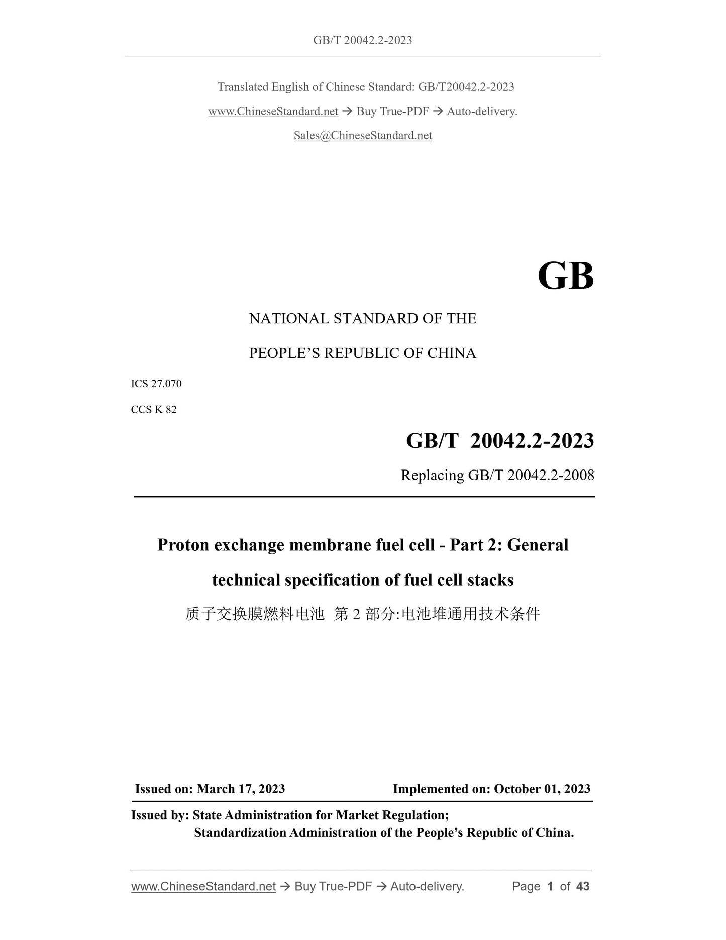
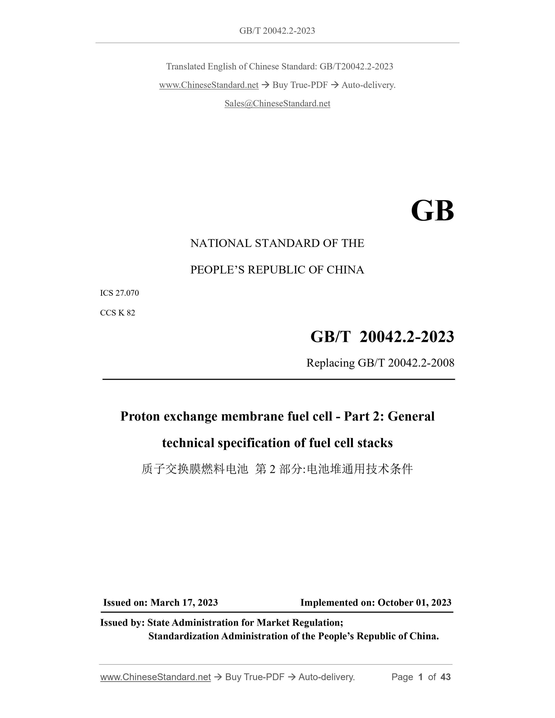
GB/T 20042.2-2023
GB
NATIONAL STANDARD OF THE
PEOPLE’S REPUBLIC OF CHINA
ICS 27.070
CCS K 82
Replacing GB/T 20042.2-2008
Proton exchange membrane fuel cell - Part 2: General
technical specification of fuel cell stacks
ISSUED ON: MARCH 17, 2023
IMPLEMENTED ON: OCTOBER 01, 2023
Issued by: State Administration for Market Regulation;
Standardization Administration of the People’s Republic of China.
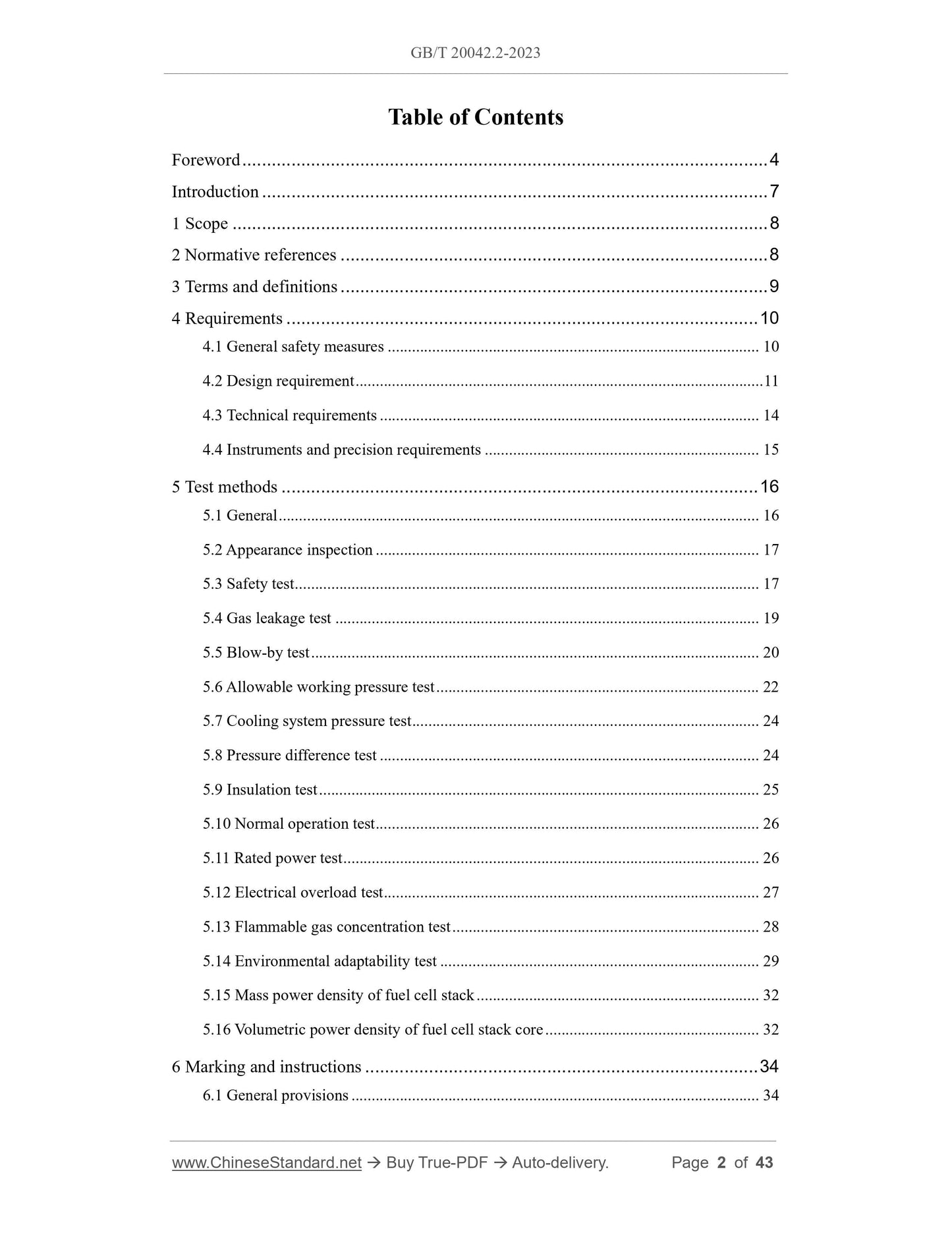
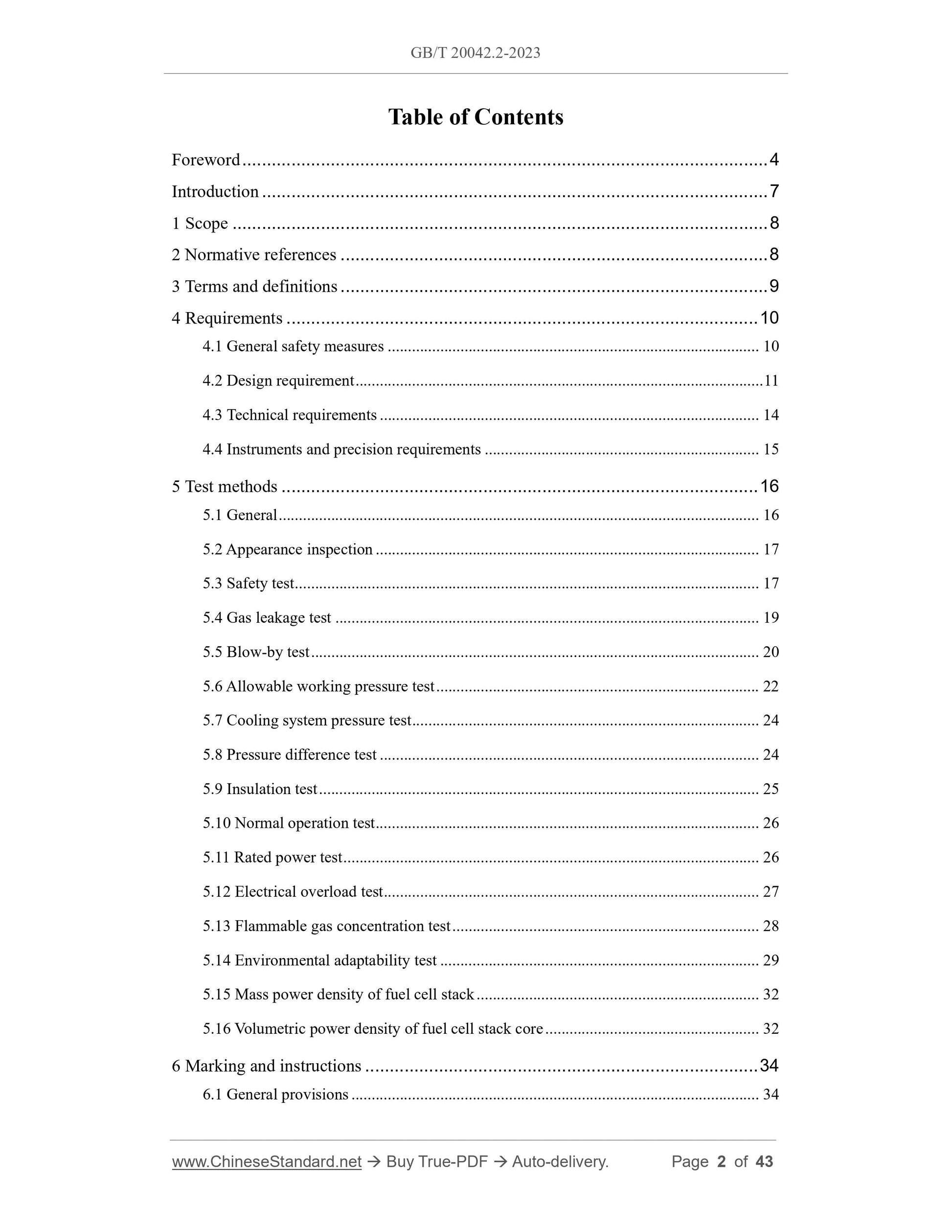
Table of Contents
Foreword ... 4
Introduction ... 7
1 Scope ... 8
2 Normative references ... 8
3 Terms and definitions ... 9
4 Requirements ... 10
4.1 General safety measures ... 10
4.2 Design requirement ... 11
4.3 Technical requirements ... 14
4.4 Instruments and precision requirements ... 15
5 Test methods ... 16
5.1 General ... 16
5.2 Appearance inspection ... 17
5.3 Safety test ... 17
5.4 Gas leakage test ... 19
5.5 Blow-by test ... 20
5.6 Allowable working pressure test ... 22
5.7 Cooling system pressure test ... 24
5.8 Pressure difference test ... 24
5.9 Insulation test ... 25
5.10 Normal operation test ... 26
5.11 Rated power test ... 26
5.12 Electrical overload test ... 27
5.13 Flammable gas concentration test ... 28
5.14 Environmental adaptability test ... 29
5.15 Mass power density of fuel cell stack ... 32
5.16 Volumetric power density of fuel cell stack core ... 32
6 Marking and instructions ... 34
6.1 General provisions ... 34
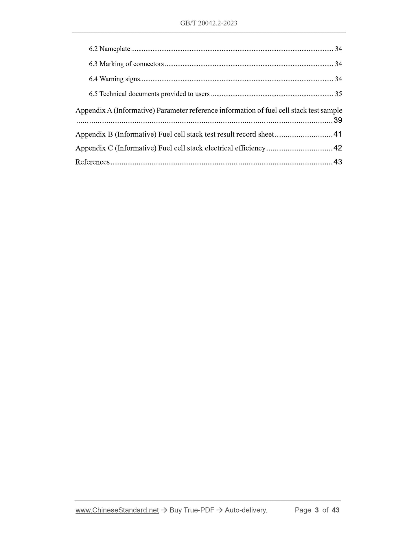
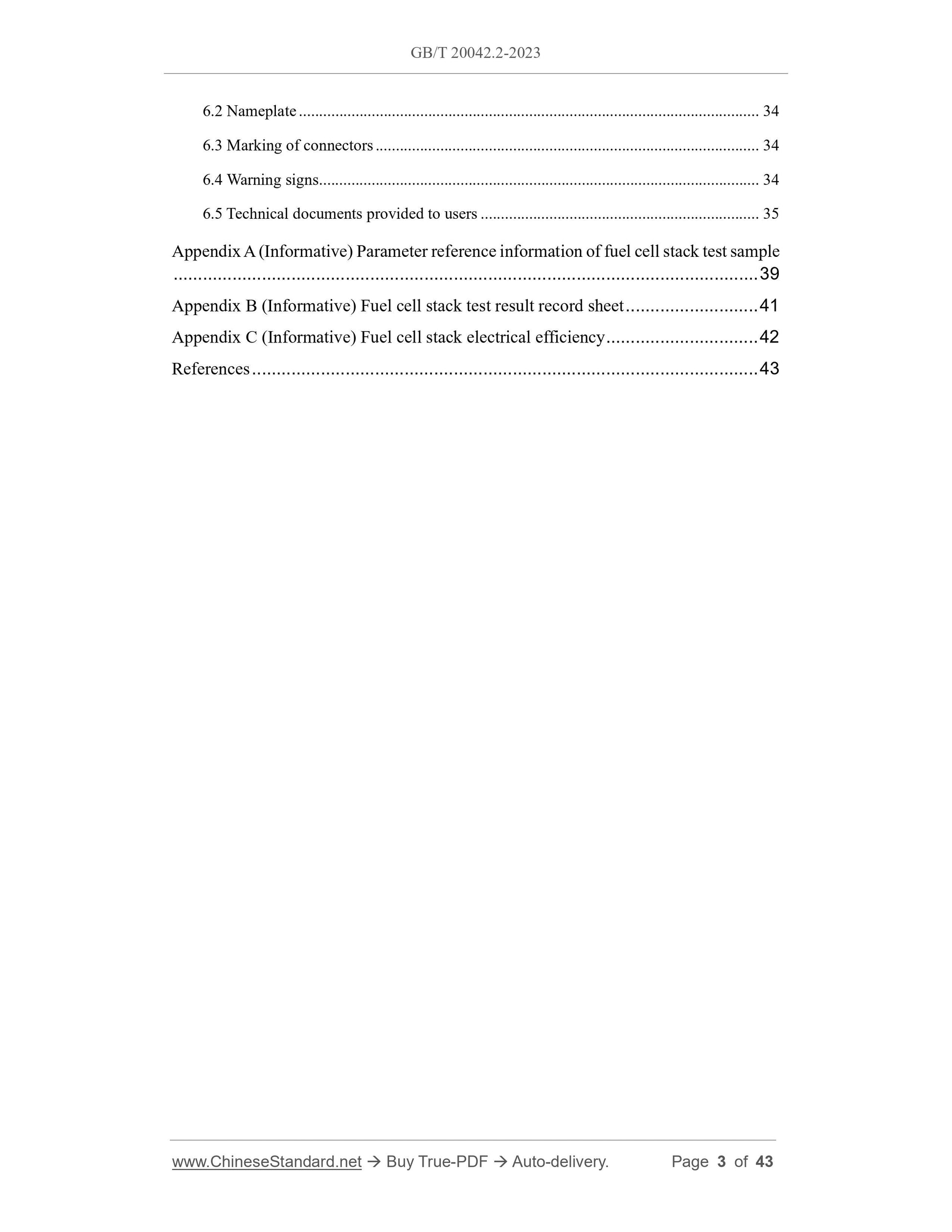
6.2 Nameplate ... 34
6.3 Marking of connectors ... 34
6.4 Warning signs ... 34
6.5 Technical documents provided to users ... 35
Appendix A (Informative) Parameter reference information of fuel cell stack test sample
... 39
Appendix B (Informative) Fuel cell stack test result record sheet ... 41
Appendix C (Informative) Fuel cell stack electrical efficiency ... 42
References ... 43
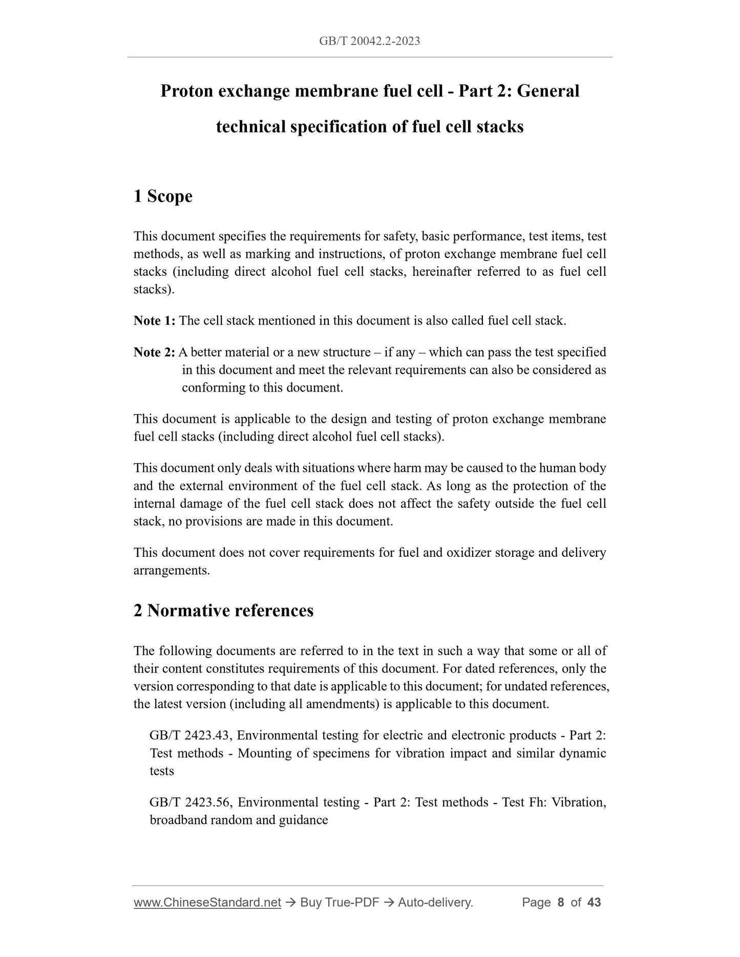
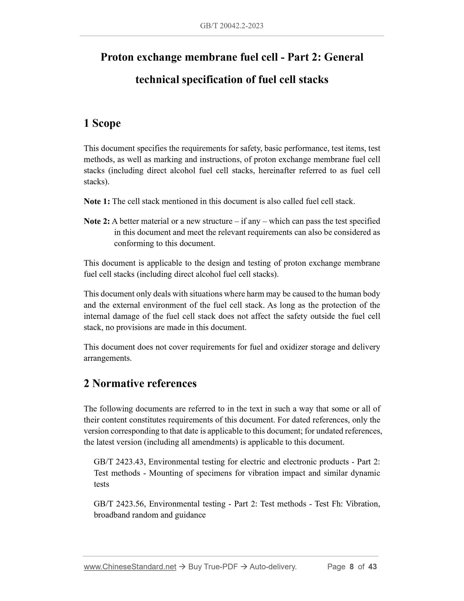
Proton exchange membrane fuel cell - Part 2: General
technical specification of fuel cell stacks
1 Scope
This document specifies the requirements for safety, basic performance, test items, test
methods, as well as marking and instructions, of proton exchange membrane fuel cell
stacks (including direct alcohol fuel cell stacks, hereinafter referred to as fuel cell
stacks).
Note 1: The cell stack mentioned in this document is also called fuel cell stack.
Note 2: A better material or a new structure – if any – which can pass the test specified
in this document and meet the relevant requirements can also be considered as
conforming to this document.
This document is applicable to the design and testing of proton exchange membrane
fuel cell stacks (including direct alcohol fuel cell stacks).
This document only deals with situations where harm may be caused to the human body
and the external environment of the fuel cell stack. As long as the protection of the
internal damage of the fuel cell stack does not affect the safety outside the fuel cell
stack, no provisions are made in this document.
This document does not cover requirements for fuel and oxidizer storage and delivery
arrangements.
2 Normative references
The following documents are referred to in the text in such a way that some or all of
their content constitutes requirements of this document. For dated references, only the
version corresponding to that date is applicable to this document; for undated references,
the latest version (including all amendments) is applicable to this document.
GB/T 2423.43, Environmental testing for electric and electronic products - Part 2:
Test methods - Mounting of specimens for vibration impact and similar dynamic
tests
GB/T 2423.56, Environmental testing - Part 2: Test methods - Test Fh: Vibration,
broadband random and guidance
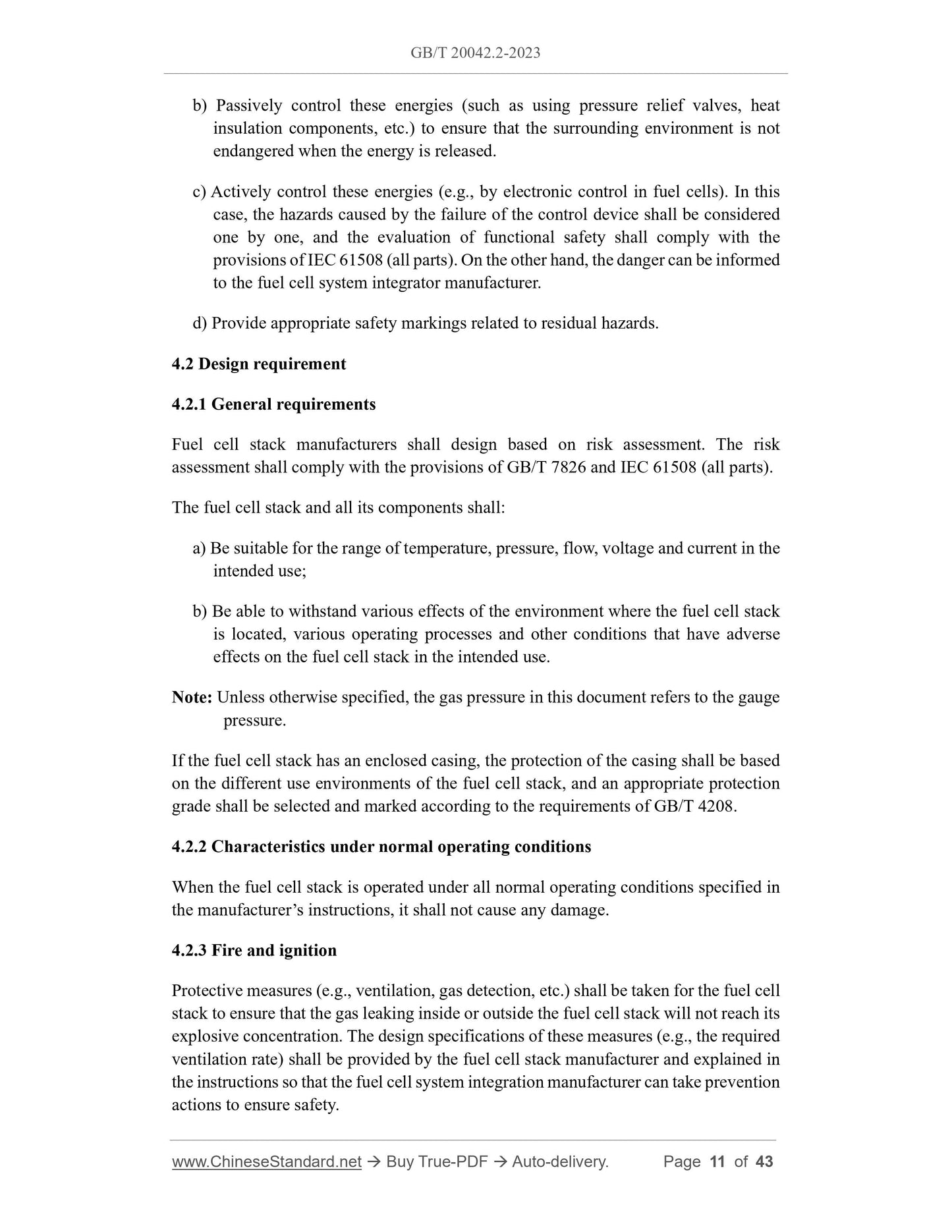
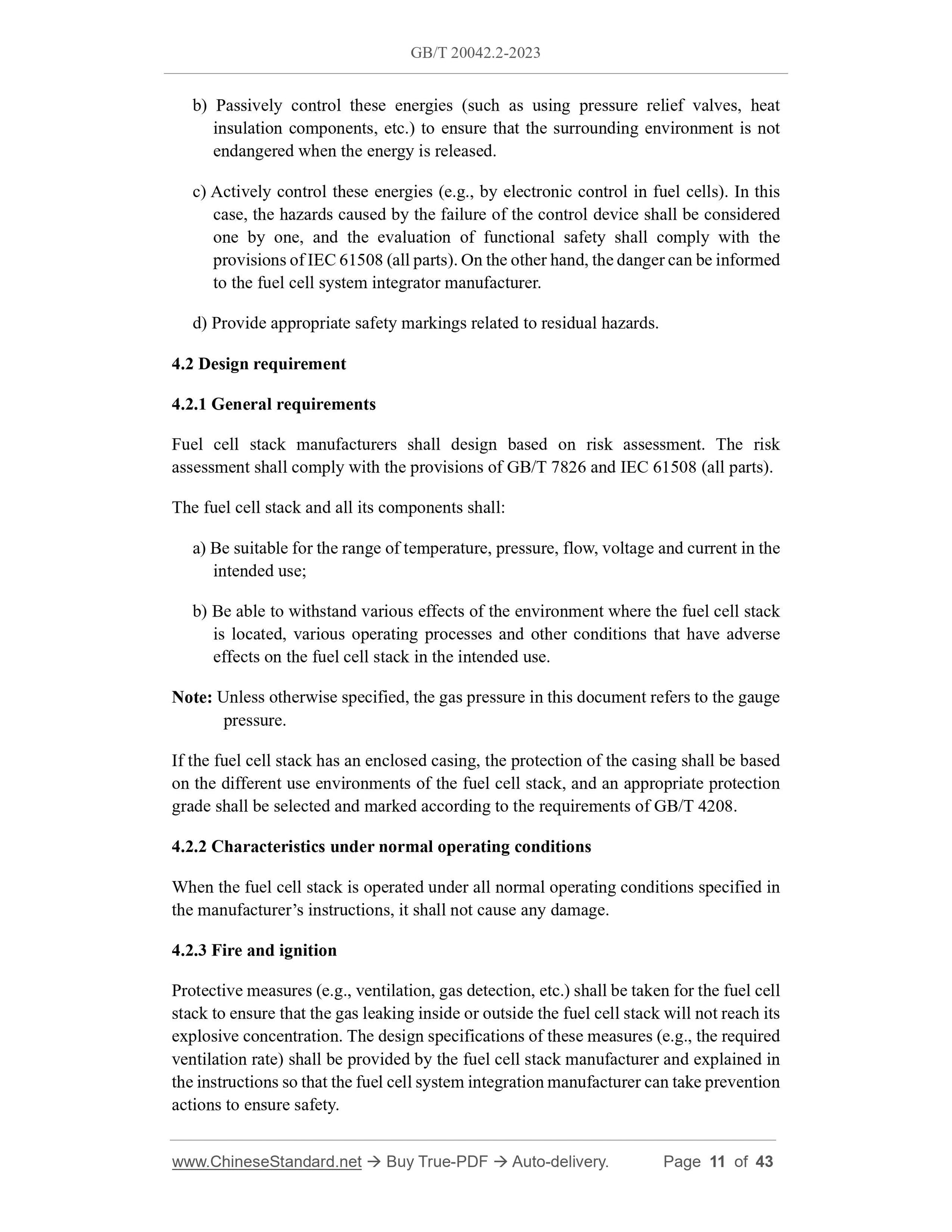
b) Passively control these energies (such as using pressure relief valves, heat
insulation components, etc.) to ensure that the surrounding environment is not
endangered when the energy is released.
c) Actively control these energies (e.g., by electronic control in fuel cells). In this
case, the hazards caused by the failure of the control device shall be considered
one by one, and the evaluation of functional safety shall comply with the
provisions of IEC 61508 (all parts). On the other hand, the danger can be informed
to the fuel cell system integrator manufacturer.
d) Provide appropriate safety markings related to residual hazards.
4.2 Design requirement
4.2.1 General requirements
Fuel cell stack manufacturers shall design based on risk assessment. The risk
assessment shall comply with the provisions of GB/T 7826 and IEC 61508 (all parts).
The fuel cell stack and all its components shall:
a) Be suitable for the range of temperature, pressure, flow, voltage and current in the
intended use;
b) Be able to withstand various effects of the environment where the fuel cell stack
is located, various operating processes and other conditions that have adverse
effects on the fuel cell stack in the intended use.
Note: Unless otherwise specified, the gas pressure in this document refers to the gauge
pressure.
If the fuel cell stack has an enclosed casing, the protection of the casing shall be based
on the different use environments of the fuel cell stack, and an appropriate protection
grade shall be selected and marked according to the requirements of GB/T 4208.
4.2.2 Characteristics under normal operating conditions
When the fuel cell stack is operated under all normal operating conditions specified in
the manufacturer’s instructions, it shall not cause any damage.
4.2.3 Fire and ignition
Protective measures (e.g., ventilation, gas detection, etc.) shall be taken for the fuel cell
stack to ensure that the gas leaking inside or outside the fuel cell stack will not reach its
explosive concentration. The design specifications of these measures (e.g., the required
ventilation rate) shall be provided by the fuel cell stack manufacturer and explained in
the instructions so that the fuel cell system integration manufacturer can take prevention
actions to ensure safety.
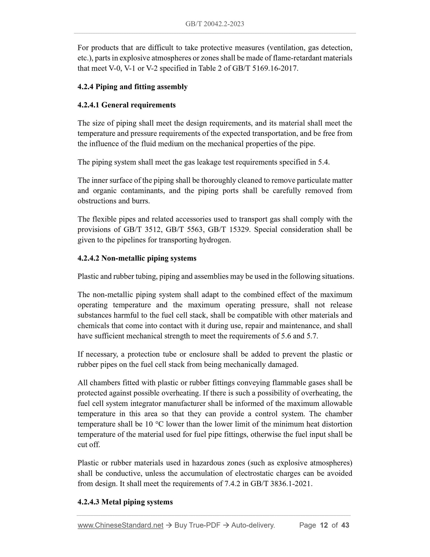
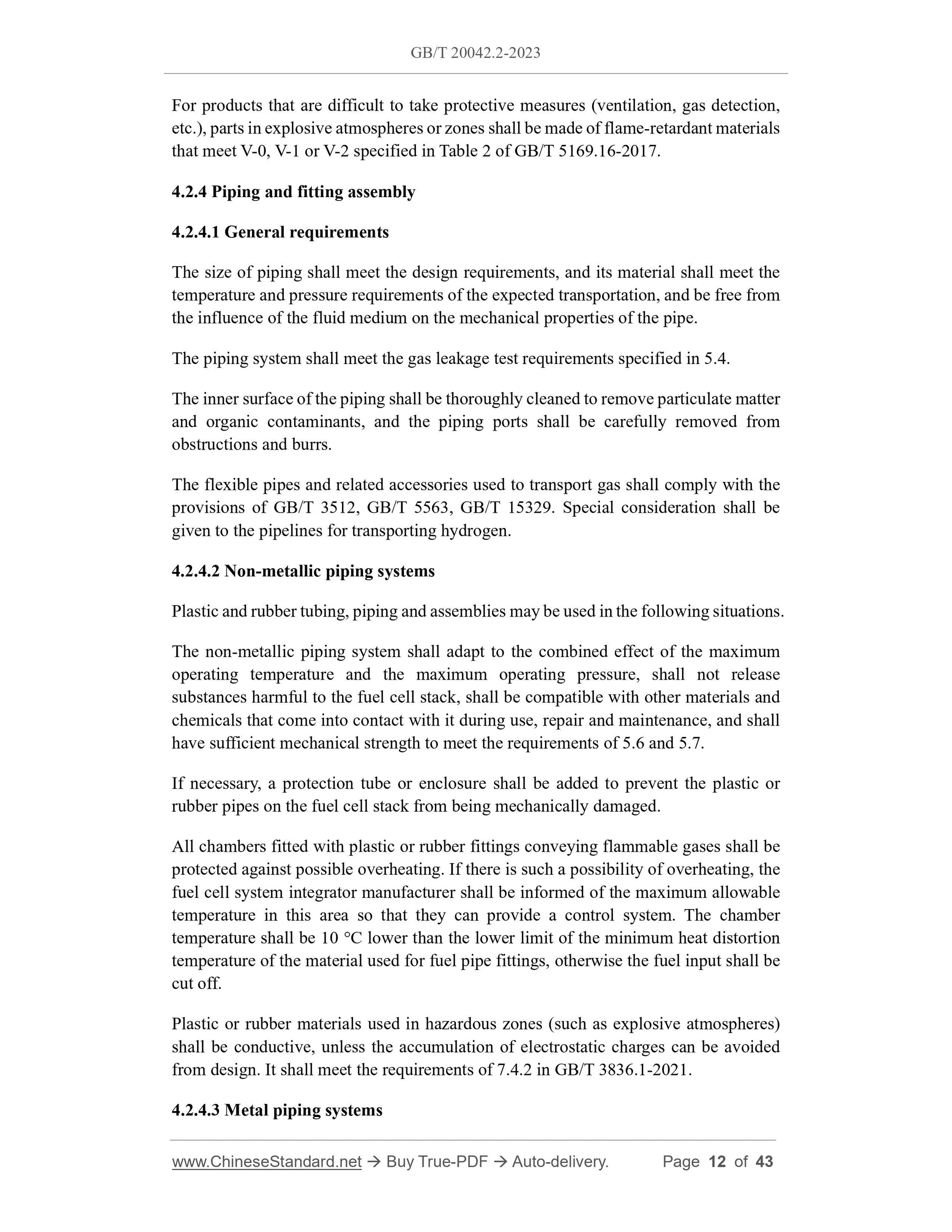
For products that are difficult to take protective measures (ventilation, gas detection,
etc.), parts in explosive atmospheres or zones shall be made of flame-retardant materials
that meet V-0, V-1 or V-2 specified in Table 2 of GB/T 5169.16-2017.
4.2.4 Piping and fitting assembly
4.2.4.1 General requirements
The size of piping shall meet the design requirements, and its material shall meet the
temperature and pressure requirements of the expected transportation, and be free from
the influence of the fluid medium on the mechanical properties of the pipe.
The piping system shall meet the gas leakage test requirements specified in 5.4.
The inner surface of the piping shall be thoroughly cleaned to remove particulate matter
and organic contaminants, and the piping ports shall be carefully removed from
obstructions and burrs.
The flexible pipes and related accessories used to transport gas shall comply with the
provisions of GB/T 3512, GB/T 5563, GB/T 15329. Special consideration shall be
given to the pipelines for transporting hydrogen.
4.2.4.2 Non-metallic piping systems
Plastic and rubber tubing, piping and assemblies may be used in the following situations.
The non-metallic piping system shall adapt to the combined effect of the maximum
operating temperature and the maximum operating pressure, shall not release
substances harmful to the fuel cell stack, shall be compatible with other materials and
chemicals that come into contact with it during use, repair and maintenance, and shall
have sufficient mechanical strength to meet the requirements of 5.6 and 5.7.
If necessary, a protection tube or enclosure shall be added to prevent the plastic or
rubber pipes on the fuel cell stack from being mechanically damaged.
All chambers fitted with plastic or rubber fittings conveying flammable gases shall be
protected against possible overheating. If there is such a possibility of overheating, the
fuel cell system integrator manufacturer shall be informed of the maximum allowable
temperature in this area so that they can provide a control system. The chamber
temperature shall be 10 °C lower than the lower limit of the minimum heat distortion
temperature of the material used for fuel pipe fittings, otherwise the fuel input shall be
cut off.
Plastic or rubber materials used in hazardous zones (such as explosive atmospheres)
shall be conductive, unless the accumulation of electrostatic charges can be avoided
from design. It shall meet the requirements of 7.4.2 in GB/T 3836.1-2021.
4.2.4.3 Metal piping systems
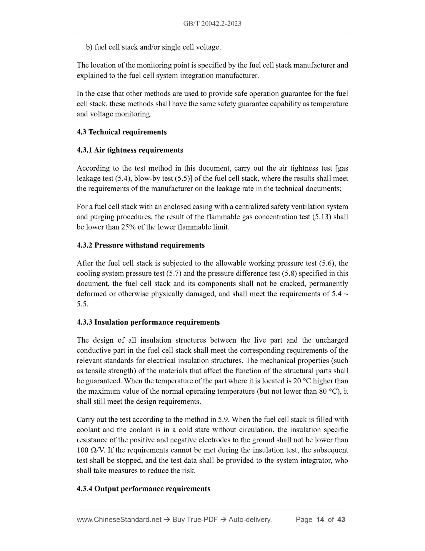
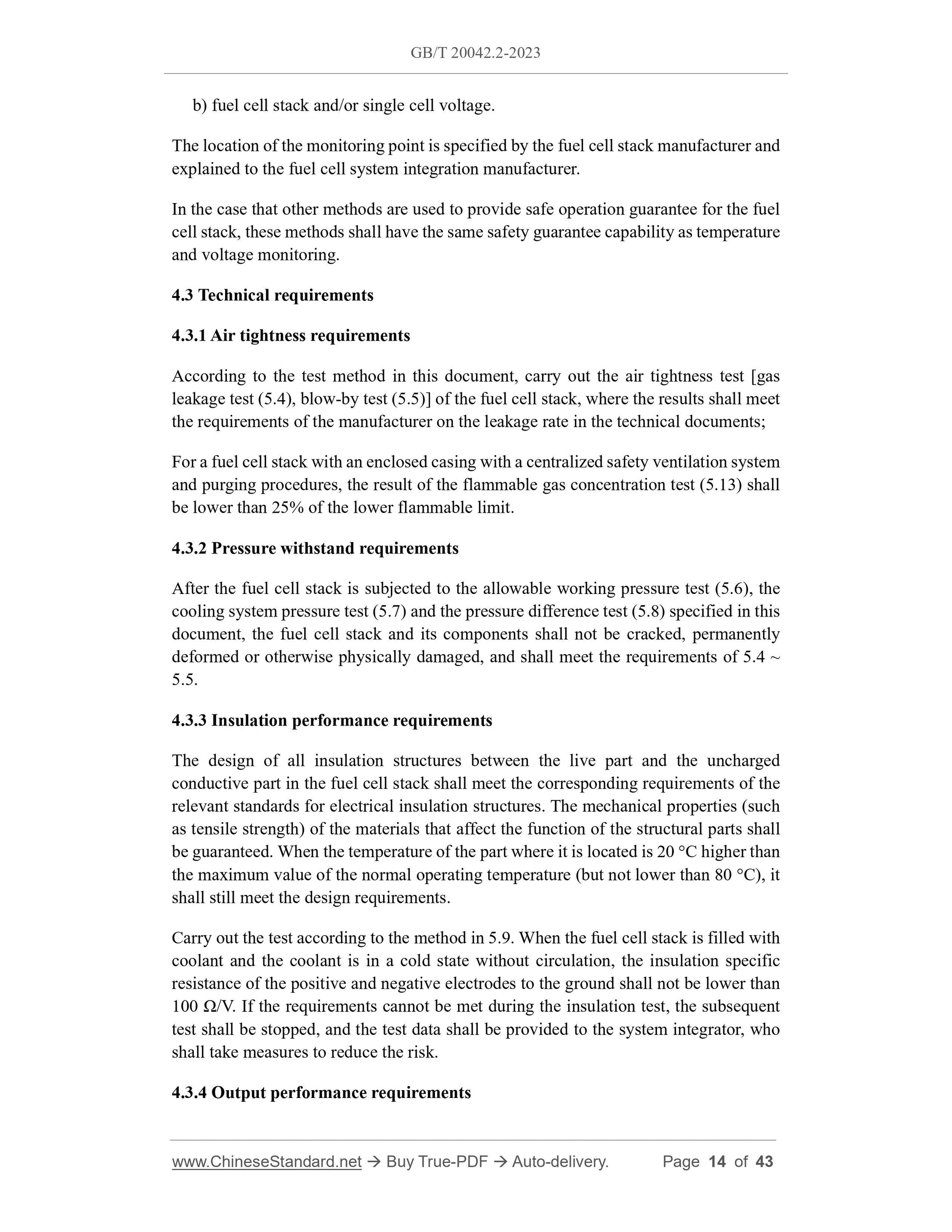
b) fuel cell stack and/or single cell voltage.
The location of the monitoring point is specified by the fuel cell stack manufacturer and
explained to the fuel cell system integration manufacturer.
In the case that other methods are used to provide safe operation guarantee for the fuel
cell stack, these methods shall have the same safety guarantee capability as temperature
and voltage monitoring.
4.3 Technical requirements
4.3.1 Air tightness requirements
According to the test method in this document, carry out the air tightness test [gas
leakage test (5.4), blow-by test (5.5)] of the fuel cell stack, where the results shall meet
the requirements of the manufacturer on the leakage rate in the technical documents;
For a fuel cell stack with an enclosed casing with a centralized safety ventilation system
and purging procedures, the result of the flammable gas concentration test (5.13) shall
be lower than 25% of the lower flammable limit.
4.3.2 Pressure withstand requirements
After the fuel cell stack is subjected to the allowable working pressure test (5.6), the
cooling system pressure test (5.7) and the pressure difference test (5.8) specified in this
document, the fuel cell stack and its components shall not be cracked, permanently
deformed or otherwise physically damaged, and shall meet the requirements of 5.4 ~
5.5.
4.3.3 Insulation performance requirements
The design of all insulation structures between the live part and the uncharged
conductive part in the fuel cell stack shall meet the corresponding requirements of the
relevant standards for electrical insulation structures. The mechanical properties (such
as tensile strength) of the materials that affect the function of the structural parts shall
be guaranteed. When the temperature of the part where it is located is 20 °C higher than
the maximum value of the normal operating temperature (but not lower than 80 °C), it
shall still meet the design requirements.
Carry out the test according to the method in 5.9. When the fuel cell stack is filled with
coolant and the coolant is in a cold state without circulation, the insulation specific
resistance of the positive and negative electrodes to the ground shall not be lower than
100 Ω/V. If the requirements cannot be met during the insulation test, the subsequent
test shall be stopped, and the test data shall be provided to the system integrator, who
shall take measures to reduce the risk.
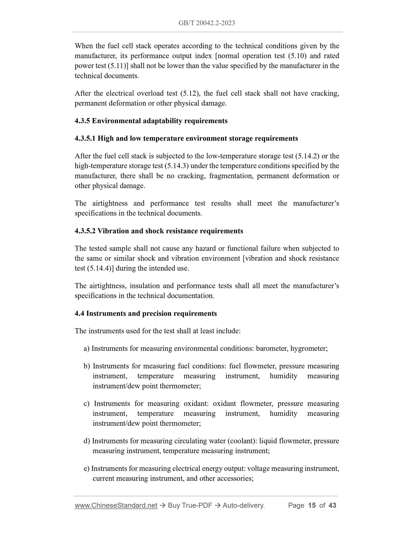
4.3.4 Output performance requirements
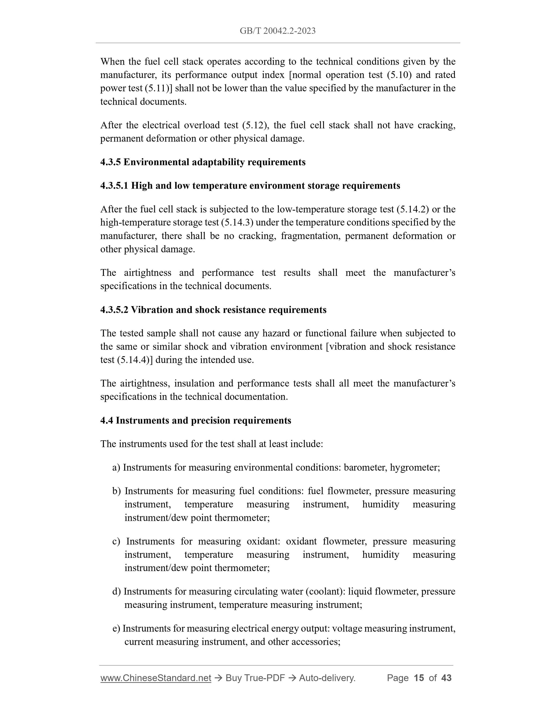
When the fuel cell stack operates according to the technical conditions given by the
manufacturer, its performance output index [normal operation test (5.10) and rated
power test (5.11)] shall not be lower than the value specified by the manufacturer in the
technical documents.
After the electrical overload test (5.12), the fuel cell stack shall not have cracking,
permanent deformation or other physical damage.
4.3.5 Environmental adaptability requirements
4.3.5.1 High and low temperature environment storage requirements
After the fuel cell stack is subjected to the low-temperature storage test (5.14.2) or the
high-temperature storage test (5.14.3) under the temperature conditions specified by the
manufacturer, there shall be no cracking, fragmentation, permanent deformation or
other physical damage.
The airtightness and performance test results shall meet the manufacturer’s
specifications in the technical documents.
4.3.5.2 Vibration and shock resistance requirements
The tested sample shall not cause any hazard or functional failure when subjected to
the same or similar shock and vibration environment [vibration and shock resistance
test (5.14.4)] during the intended use.
The airtightness, insulation and performance tests shall all meet the manufacturer’s
specifications in the technical documentation.
4.4 Instruments and precision requirements
The instruments used for the test shall at least include:
a) Instruments for measuring environmental conditions: barometer, hygrometer;
b) Instruments for measuring fuel conditions: fuel flowmeter, pressure measuring
instrument, temperature measuring instrument, humidity measuring
instrument/dew point thermometer;
c) Instruments for measuring oxidant: oxidant flowmeter, pressure measuring
instrument, temperature measuring instrument, humidity measuring
instrument/dew point thermometer;
d) Instruments for measuring circulating water (coolant): liquid flowmeter, pressure
measuring instrument, temperature measuring instrument;
e) Instruments for measuring electrical energy output: voltage measuring instrument,
current measuring instrument, and other accessories;
The allowable working pressure test of the fuel cell stack shall be carried out at the
highest and lowest operating temperature respectively, and the test medium shall be
nitrogen.
If the manufacturer provides a severity, perform the test in accordance with the
conditions of high severity provided by the manufacturer; if not, perform the test
according to the following requirements.
If the internal pressure of the anode chamber and cathode chamber of the fuel cell stack
is the same or the pressure difference is ≤30 kPa during normal operation, they can be
connected to each other during the test. If the fuel cell stack has a cooling channel and
the working pressure is the same as that of the anode chamber and the cathode chamber
or the pressure difference is ≤ 30 kPa, the channel can also be tested for the allowable
workin...
Share