1
/
of
12
www.ChineseStandard.us -- Field Test Asia Pte. Ltd.
GB/T 19237-2021 English PDF (GB/T19237-2021)
Regular price
$405.00
Regular price
Sale price
$405.00
Unit price
/
per
Shipping calculated at checkout.
Couldn't load pickup availability
GB/T 19237-2021: Compressed natural gas dispenser for vehicles
Delivery: 9 seconds. Download (& Email) true-PDF + Invoice.
Get Quotation: Click GB/T 19237-2021 (Self-service in 1-minute)
Historical versions (Master-website): GB/T 19237-2021
Preview True-PDF (Reload/Scroll-down if blank)
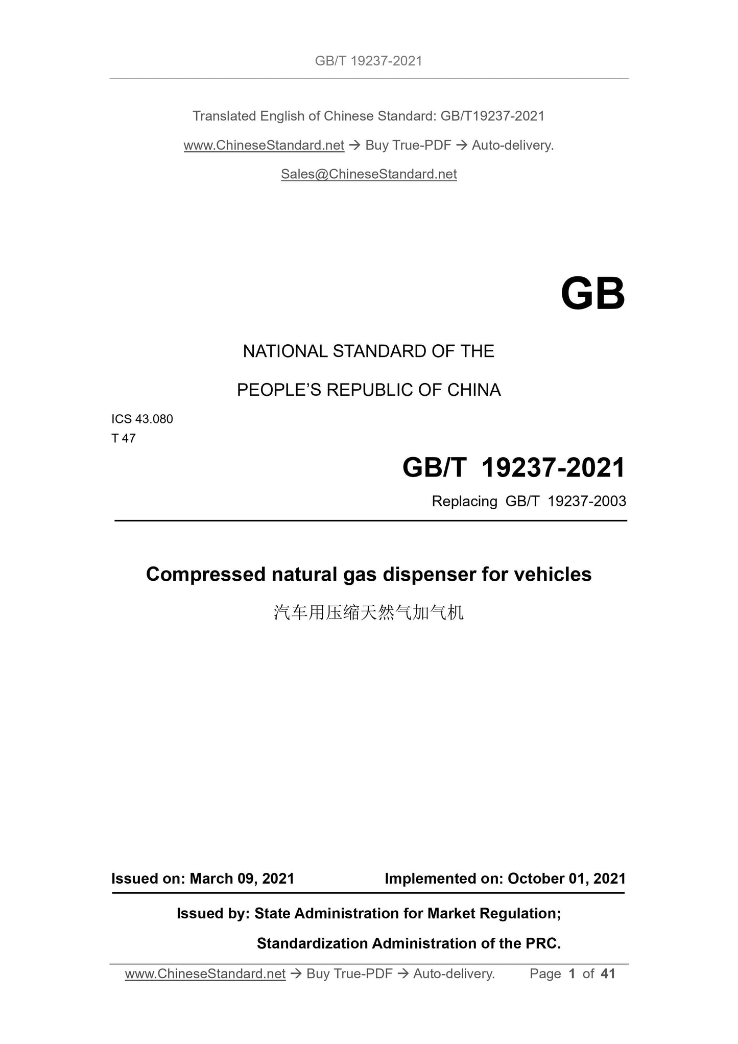
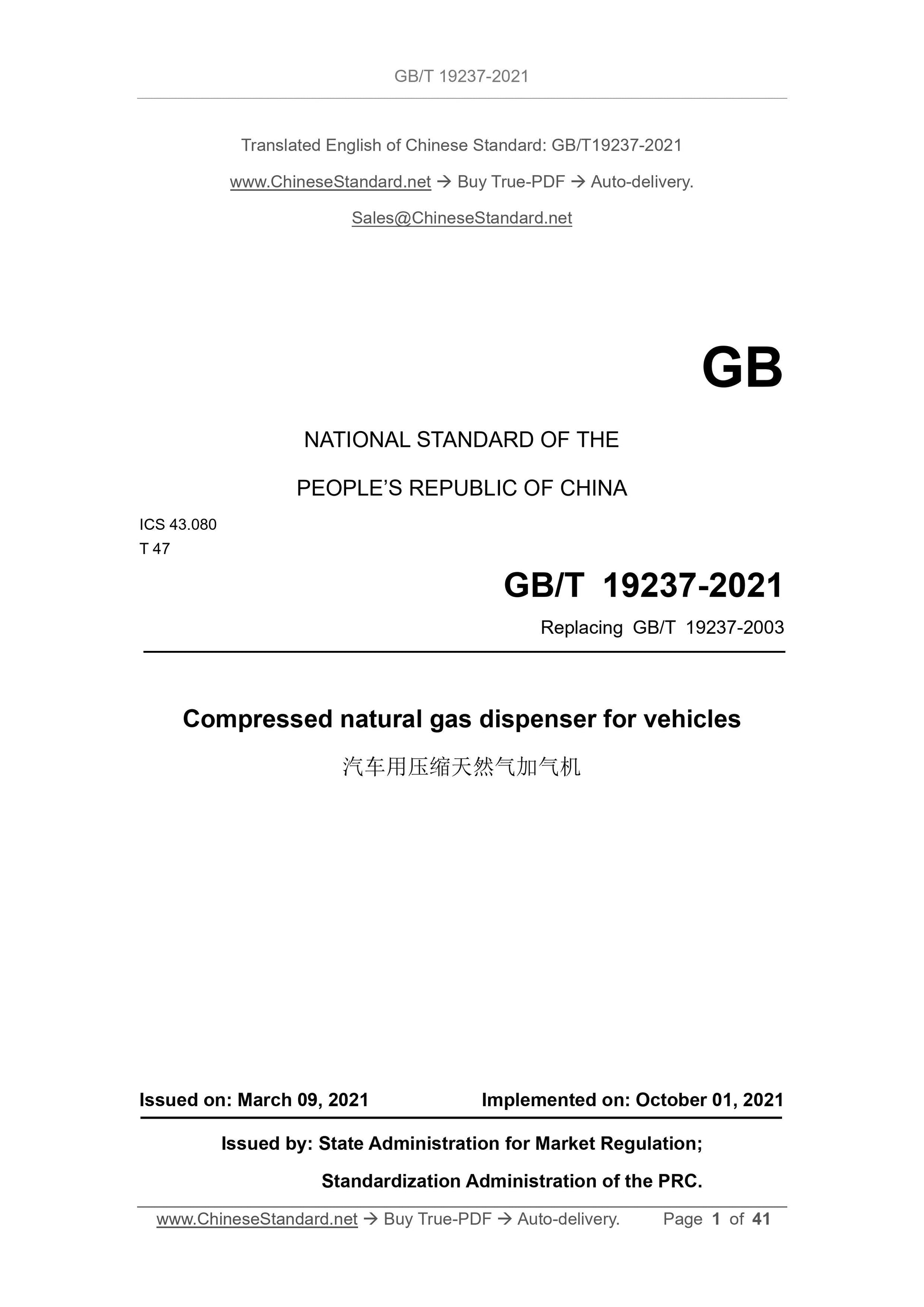
GB/T 19237-2021
GB
NATIONAL STANDARD OF THE
PEOPLE’S REPUBLIC OF CHINA
ICS 43.080
T 47
Replacing GB/T 19237-2003
Compressed natural gas dispenser for vehicles
ISSUED ON: MARCH 09, 2021
IMPLEMENTED ON: OCTOBER 01, 2021
Issued by: State Administration for Market Regulation;
Standardization Administration of the PRC.
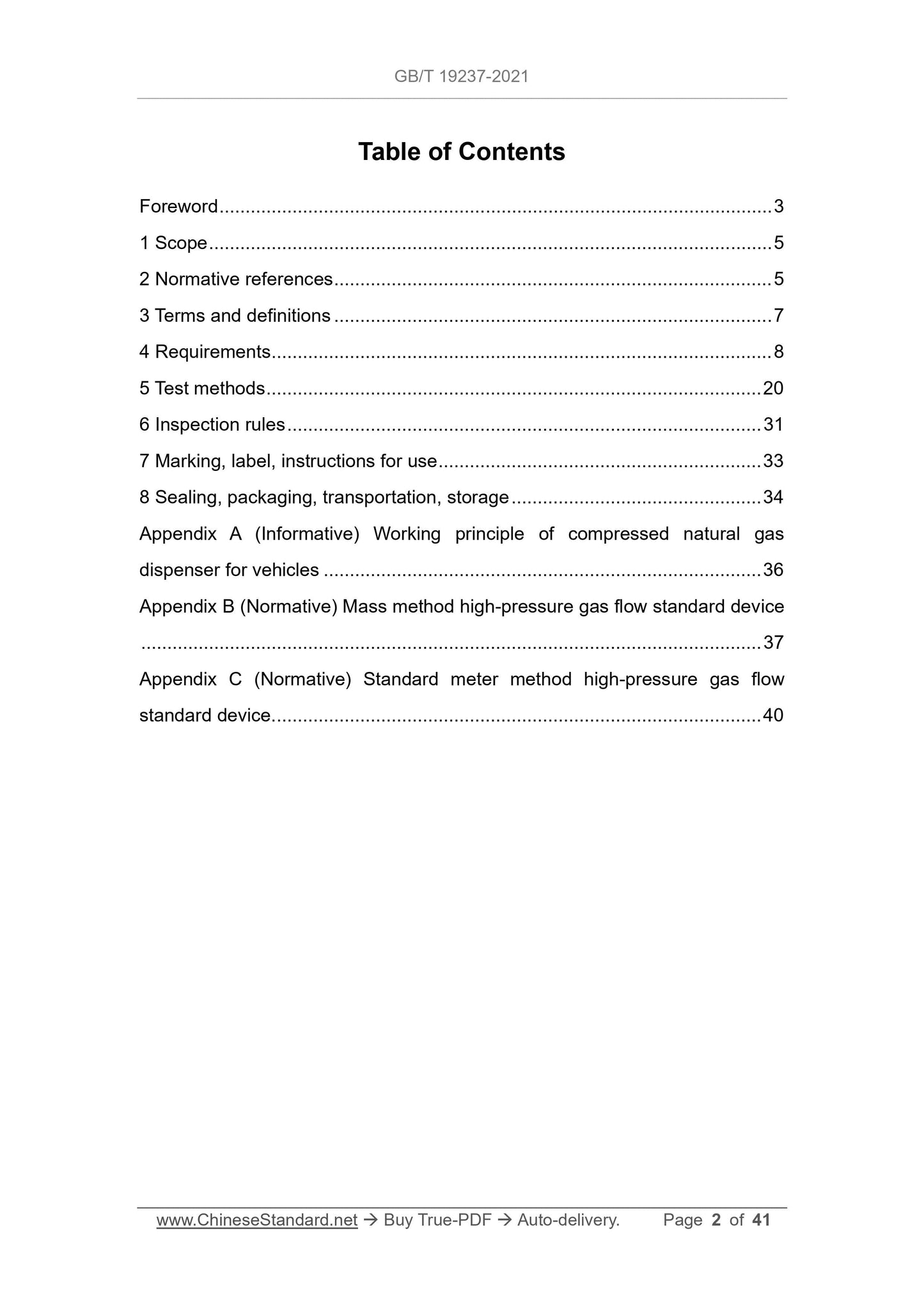
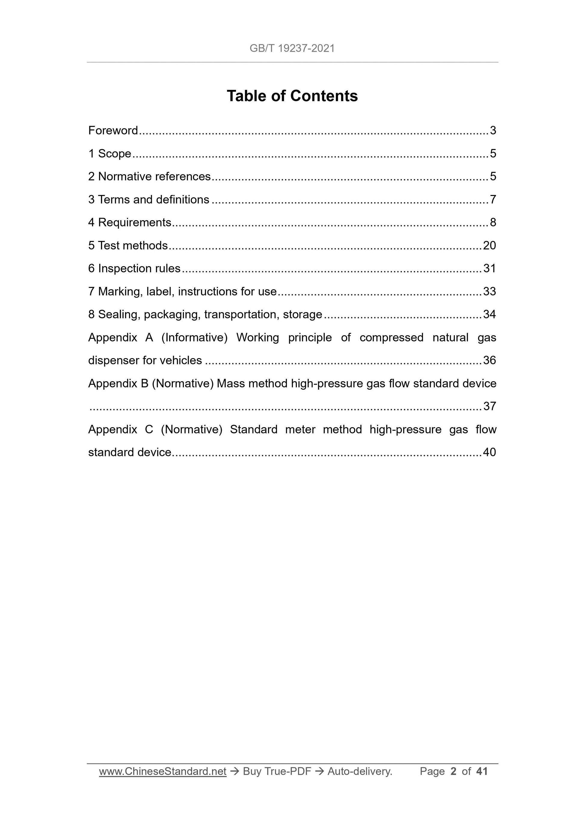
Table of Contents
Foreword ... 3
1 Scope ... 5
2 Normative references ... 5
3 Terms and definitions ... 7
4 Requirements ... 8
5 Test methods ... 20
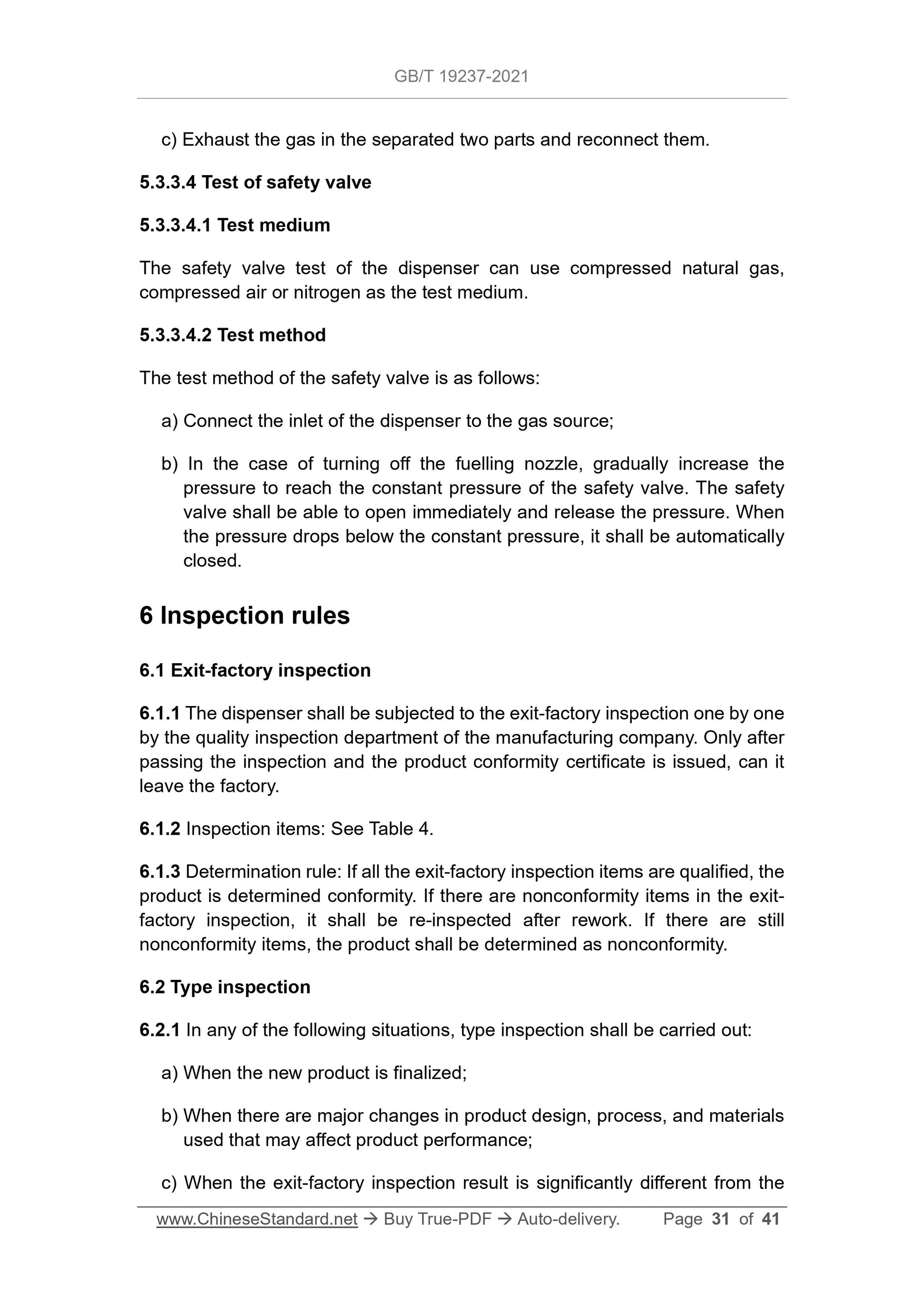
6 Inspection rules ... 31
7 Marking, label, instructions for use ... 33
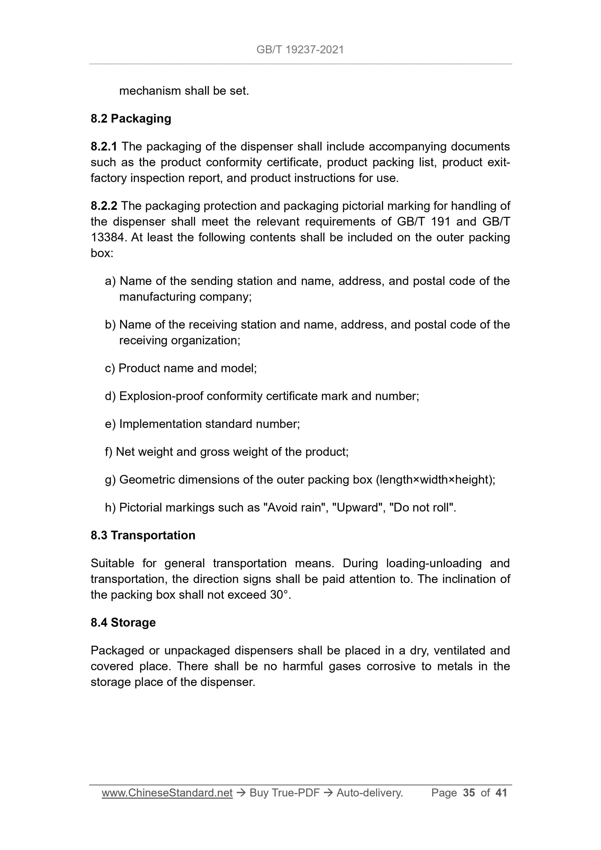
8 Sealing, packaging, transportation, storage ... 34
Appendix A (Informative) Working principle of compressed natural gas
dispenser for vehicles ... 36
Appendix B (Normative) Mass method high-pressure gas flow standard device
... 37
Appendix C (Normative) Standard meter method high-pressure gas flow
standard device ... 40
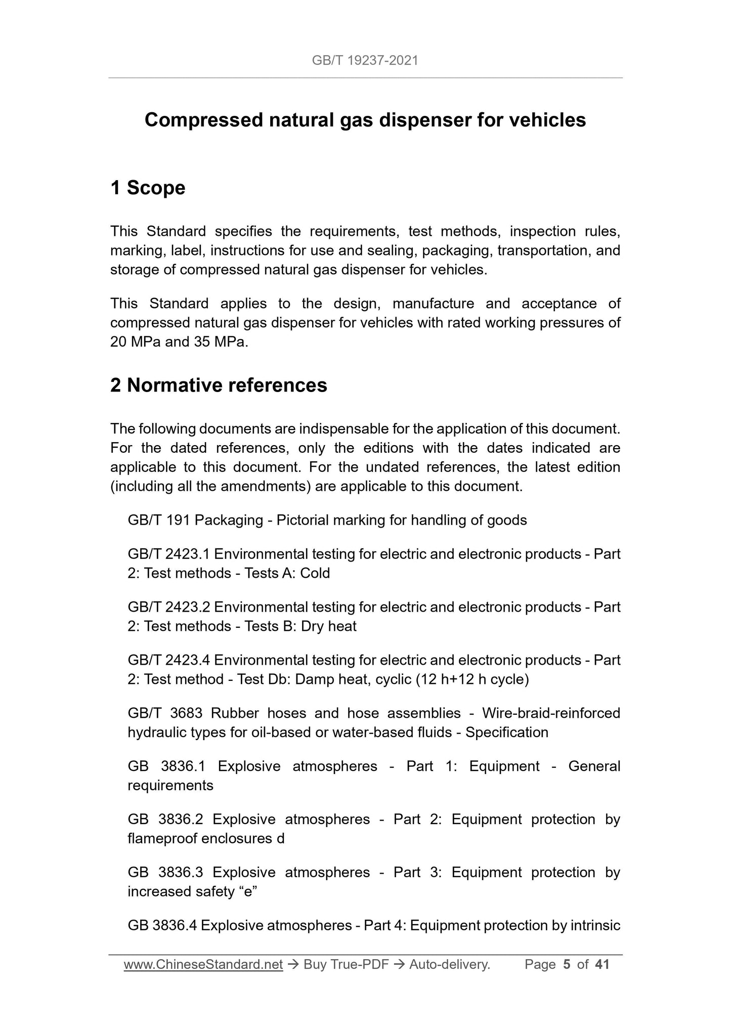
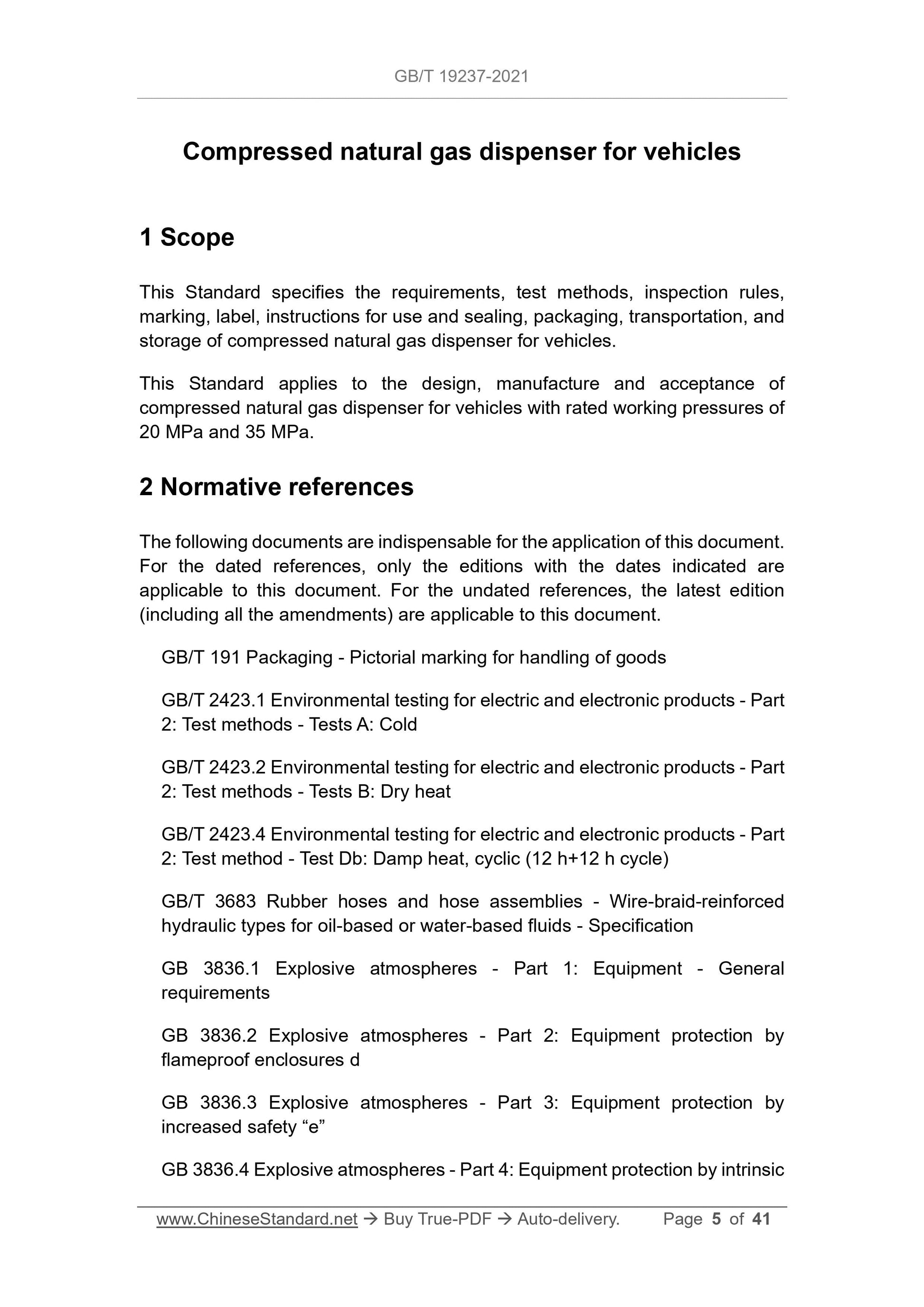
Compressed natural gas dispenser for vehicles
1 Scope
This Standard specifies the requirements, test methods, inspection rules,
marking, label, instructions for use and sealing, packaging, transportation, and
storage of compressed natural gas dispenser for vehicles.
This Standard applies to the design, manufacture and acceptance of
compressed natural gas dispenser for vehicles with rated working pressures of
20 MPa and 35 MPa.
2 Normative references
The following documents are indispensable for the application of this document.
For the dated references, only the editions with the dates indicated are
applicable to this document. For the undated references, the latest edition
(including all the amendments) are applicable to this document.
GB/T 191 Packaging - Pictorial marking for handling of goods
GB/T 2423.1 Environmental testing for electric and electronic products - Part
2: Test methods - Tests A: Cold
GB/T 2423.2 Environmental testing for electric and electronic products - Part
2: Test methods - Tests B: Dry heat
GB/T 2423.4 Environmental testing for electric and electronic products - Part
2: Test method - Test Db: Damp heat, cyclic (12 h+12 h cycle)
GB/T 3683 Rubber hoses and hose assemblies - Wire-braid-reinforced
hydraulic types for oil-based or water-based fluids - Specification
GB 3836.1 Explosive atmospheres - Part 1: Equipment - General
requirements
GB 3836.2 Explosive atmospheres - Part 2: Equipment protection by
flameproof enclosures d
GB 3836.3 Explosive atmospheres - Part 3: Equipment protection by
increased safety “e”
GB 3836.4 Explosive atmospheres - Part 4: Equipment protection by intrinsic
GB 50156 Code for design and construction of filling station
JJG 996 Verification Regulation of Compressed Natural Gas Dispensers
JTG B01 Technical Standard of Highway Engineering
SY/T 6535 The underground storage well for high-compression gas
TSG 21-2016 Supervision Regulation on Safety Technology for Stationary
Pressure Vessel
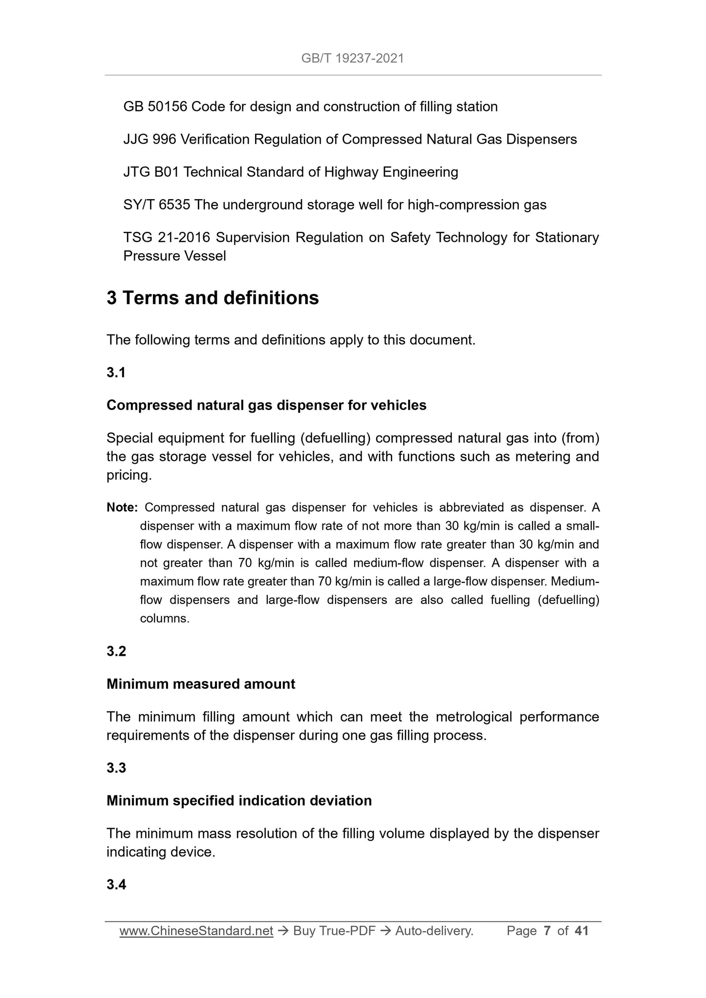
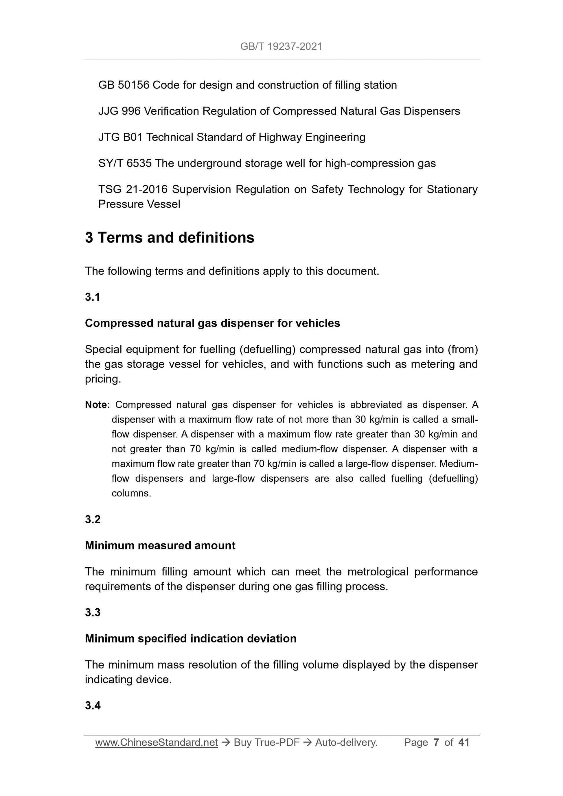
3 Terms and definitions
The following terms and definitions apply to this document.
3.1
Compressed natural gas dispenser for vehicles
Special equipment for fuelling (defuelling) compressed natural gas into (from)
the gas storage vessel for vehicles, and with functions such as metering and
pricing.
Note: Compressed natural gas dispenser for vehicles is abbreviated as dispenser. A
dispenser with a maximum flow rate of not more than 30 kg/min is called a small-
flow dispenser. A dispenser with a maximum flow rate greater than 30 kg/min and
not greater than 70 kg/min is called medium-flow dispenser. A dispenser with a
maximum flow rate greater than 70 kg/min is called a large-flow dispenser. Medium-
flow dispensers and large-flow dispensers are also called fuelling (defuelling)
columns.
3.2
Minimum measured amount
The minimum filling amount which can meet the metrological performance
requirements of the dispenser during one gas filling process.
3.3
Minimum specified indication deviation
The minimum mass resolution of the filling volume displayed by the dispenser
indicating device.
3.4
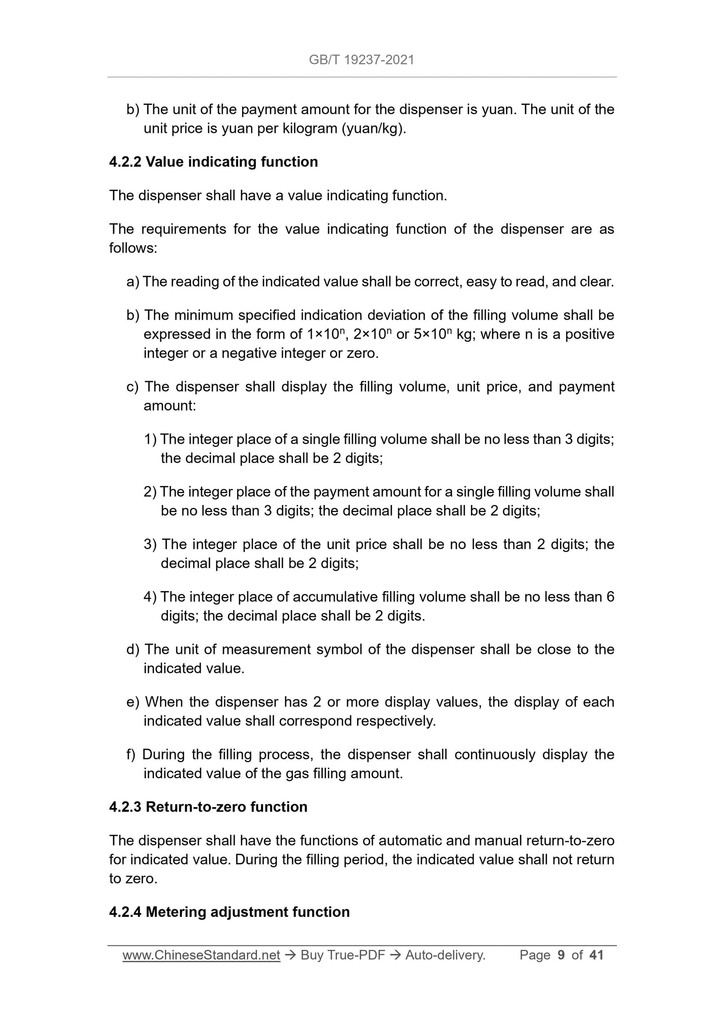
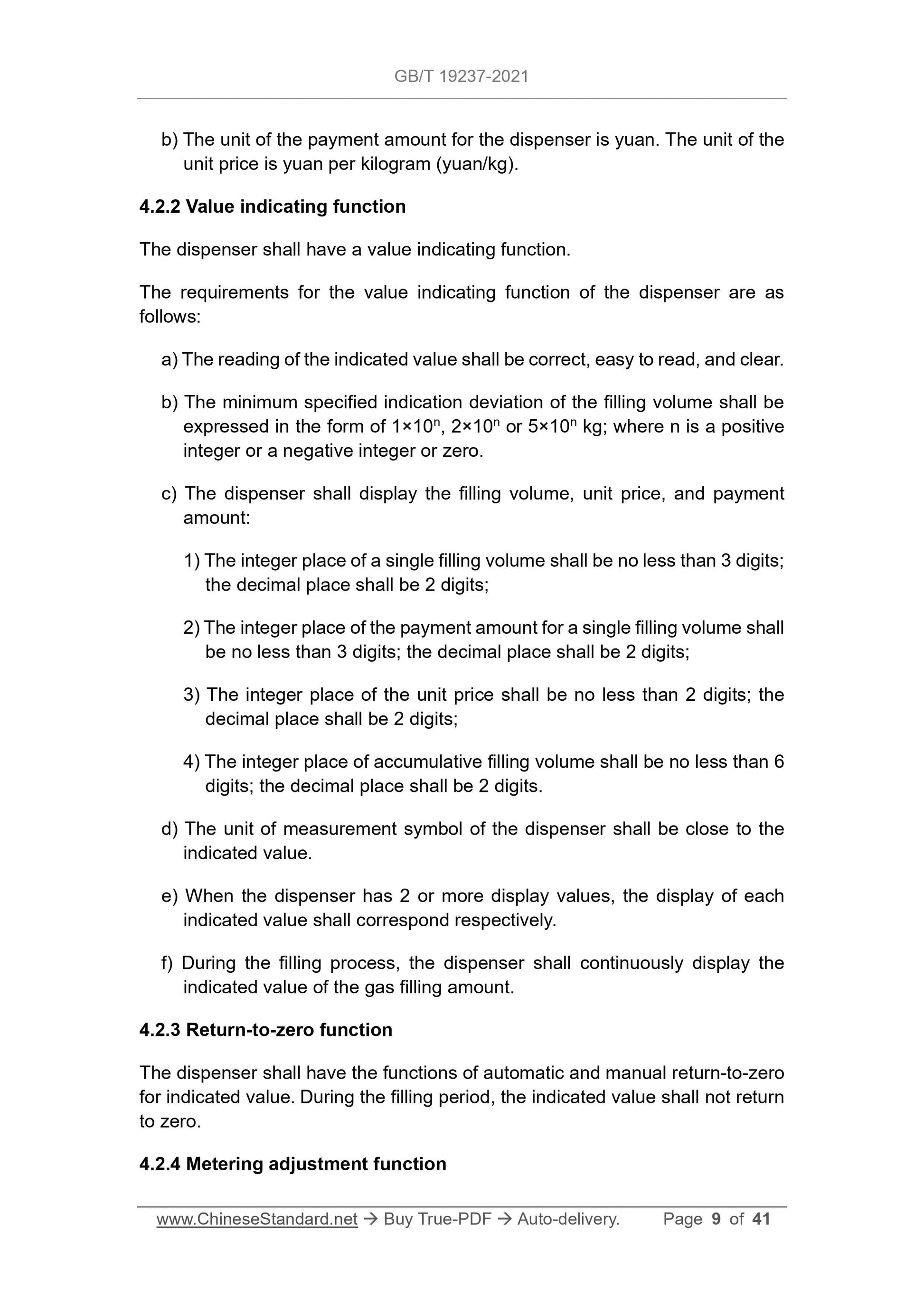
b) The unit of the payment amount for the dispenser is yuan. The unit of the
unit price is yuan per kilogram (yuan/kg).
4.2.2 Value indicating function
The dispenser shall have a value indicating function.
The requirements for the value indicating function of the dispenser are as
follows:
a) The reading of the indicated value shall be correct, easy to read, and clear.
b) The minimum specified indication deviation of the filling volume shall be
expressed in the form of 1×10n, 2×10n or 5×10n kg; where n is a positive
integer or a negative integer or zero.
c) The dispenser shall display the filling volume, unit price, and payment
amount:
1) The integer place of a single filling volume shall be no less than 3 digits;
the decimal place shall be 2 digits;
2) The integer place of the payment amount for a single filling volume shall
be no less than 3 digits; the decimal place shall be 2 digits;
3) The integer place of the unit price shall be no less than 2 digits; the
decimal place shall be 2 digits;
4) The integer place of accumulative filling volume shall be no less than 6
digits; the decimal place shall be 2 digits.
d) The unit of measurement symbol of the dispenser shall be close to the
indicated value.
e) When the dispenser has 2 or more display values, the display of each
indicated value shall correspond respectively.
f) During the filling process, the dispenser shall continuously display the
indicated value of the gas filling amount.
4.2.3 Return-to-zero function
The dispenser shall have the functions of automatic and manual return-to-zero
for indicated value. During the filling period, the indicated value shall not return
to zero.
4.2.4 Metering adjustment function
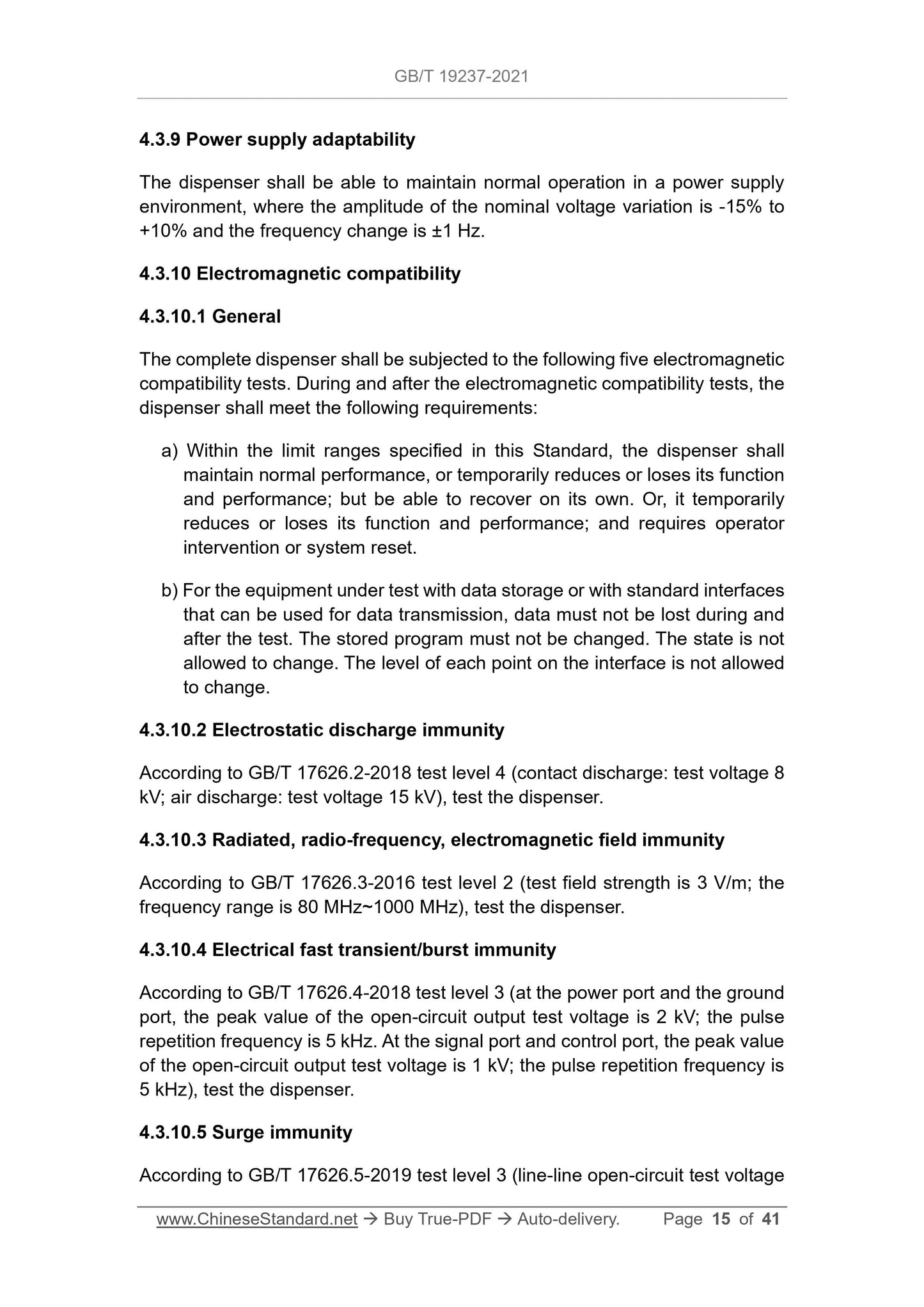
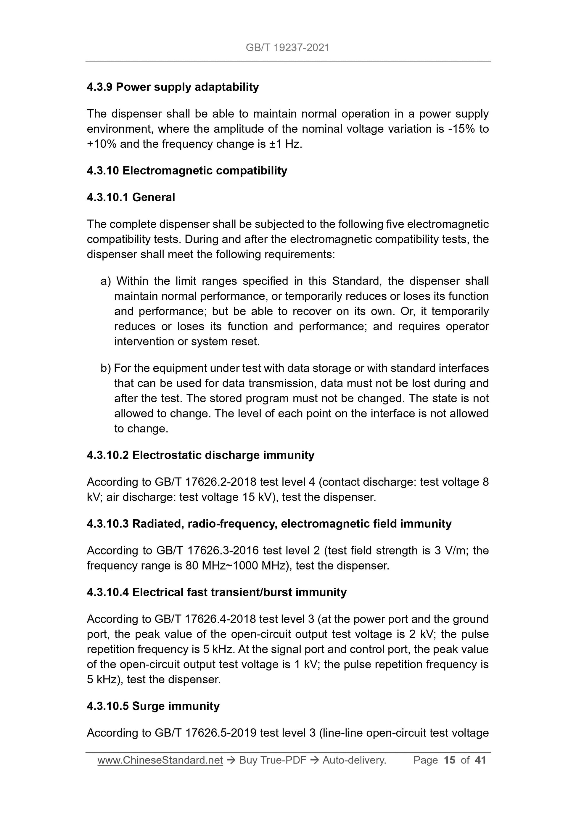
4.3.9 Power supply adaptability
The dispenser shall be able to maintain normal operation in a power supply
environment, where the amplitude of the nominal voltage variation is -15% to
+10% and the frequency change is ±1 Hz.
4.3.10 Electromagnetic compatibility
4.3.10.1 General
The complete dispenser shall be subjected to the following five electromagnetic
compatibility tests. During and after the electromagnetic compatibility tests, the
dispenser shall meet the following requirements:
a) Within the limit ranges specified in this Standard, the dispenser shall
maintain normal performance, or temporarily reduces or loses its function
and performance; but be able to recover on its own. Or, it temporarily
reduces or loses its function and performance; and requires operator
intervention or system reset.
b) For the equipment under test with data storage or with standard interfaces
that can be used for data transmission, data must not be lost during and
after the test. The stored program must not be changed. The state is not
allowed to change. The level of each point on the interface is not allowed
to change.
4.3.10.2 Electrostatic discharge immunity
According to GB/T 17626.2-2018 test level 4 (contact discharge: test voltage 8
kV; air discharge: test voltage 15 kV), test the dispenser.
4.3.10.3 Radiated, radio-frequency, electromagnetic field immunity
According to GB/T 17626.3-2016 test level 2 (test field strength is 3 V/m; the
frequency range is 80 MHz~1000 MHz), test the dispenser.
4.3.10.4 Electrical fast transient/burst immunity
According to GB/T 17626.4-2018 test level 3 (at the power port and the ground
port, the peak value of the open-circuit output test voltage is 2 kV; the pulse
repetition frequency is 5 kHz. At the signal port and control port, the peak value
of the open-circuit output test voltage is 1 kV; the pulse repetition frequency is
5 kHz), test the dispenser.
4.3.10.5 Surge immunity
According to GB/T 17626.5-2019 test level 3 (line-line open-circuit test voltage
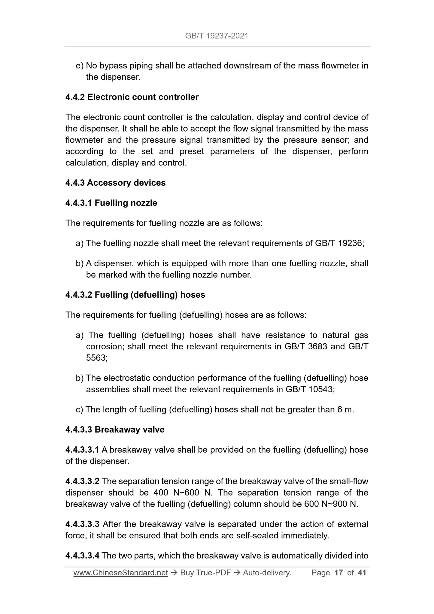
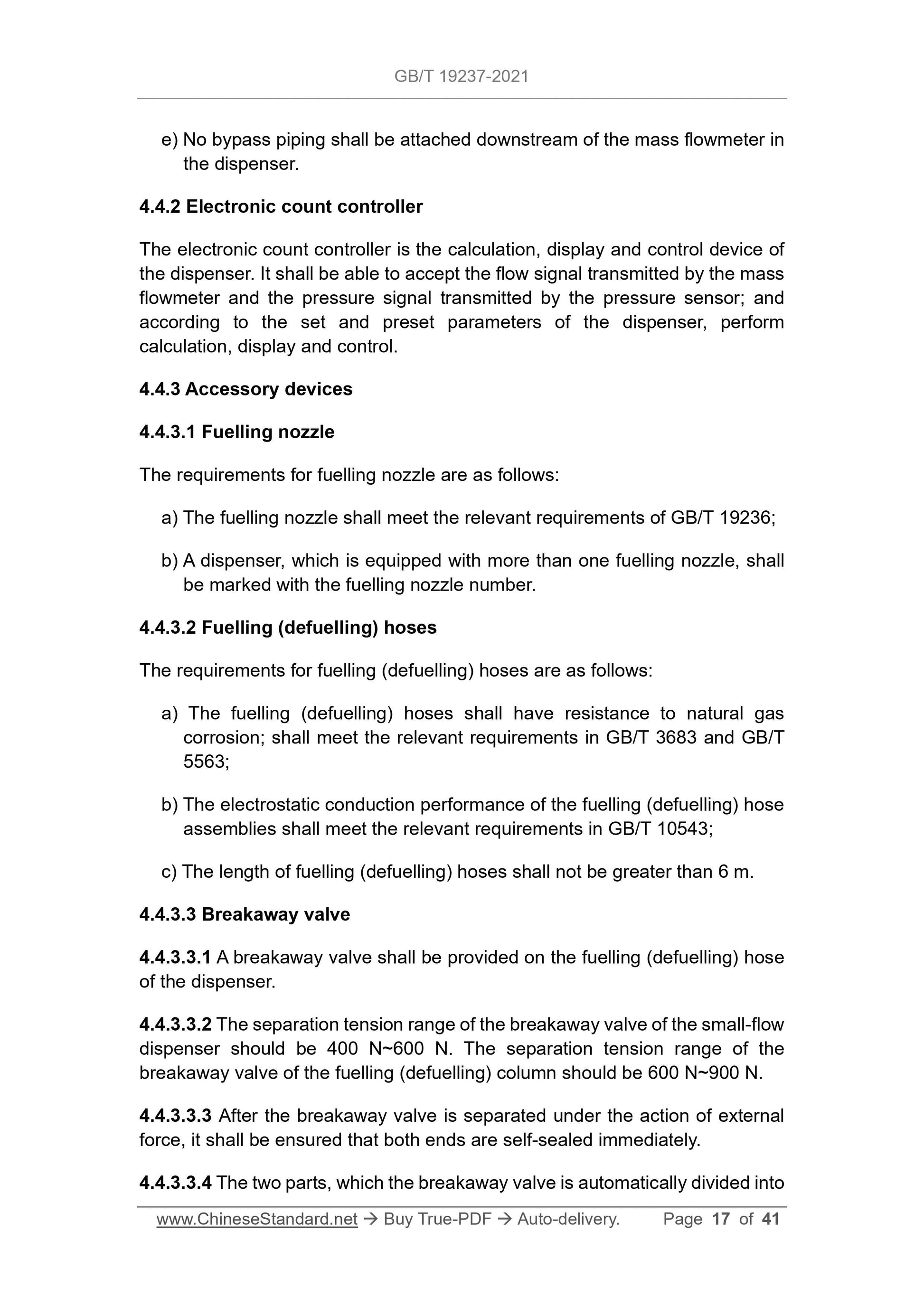
e) No bypass piping shall be attached downstream of the mass flowmeter in
the dispenser.
4.4.2 Electronic count controller
The electronic count controller is the calculation, display and control device of
the dispenser. It shall be able to accept the flow signal transmitted by the mass
flowmeter and the pressure signal transmitted by the pressure sensor; and
according to the set and preset parameters of the dispenser, perform
calculation, display and control.
4.4.3 Accessory devices
4.4.3.1 Fuelling nozzle
The requirements for fuelling nozzle are as follows:
a) The fuelling nozzle shall meet the relevant requirements of GB/T 19236;
b) A dispenser, which is equipped with more than one fuelling nozzle, shall
be marked with the fuelling nozzle number.
4.4.3.2 Fuelling (defuelling) hoses
The requirements for fuelling (defuelling) hoses are as follows:
a) The fuelling (defuelling) hoses shall have resistance to natural gas
corrosion; shall meet the relevant requirements in GB/T 3683 and GB/T
5563;
b) The electrostatic conduction performance of the fuelling (defuelling) hose
assemblies shall meet the relevant requirements in GB/T 10543;
c) The length of fuelling (defuelling) hoses shall not be greater than 6 m.
4.4.3.3 Breakaway valve
4.4.3.3.1 A breakaway valve shall be provided on the fuelling (defuelling) hose
of the dispenser.
4.4.3.3.2 The separation tension range of the breakaway valve of the small-flow
dispenser should be 400 N~600 N. The separation tension range of the
breakaway valve of the fuelling (defuelling) column should be 600 N~900 N.
4.4.3.3.3 After the breakaway valve is separated under the action of external
force, it shall be ensured that both ends are self-sealed immediately.
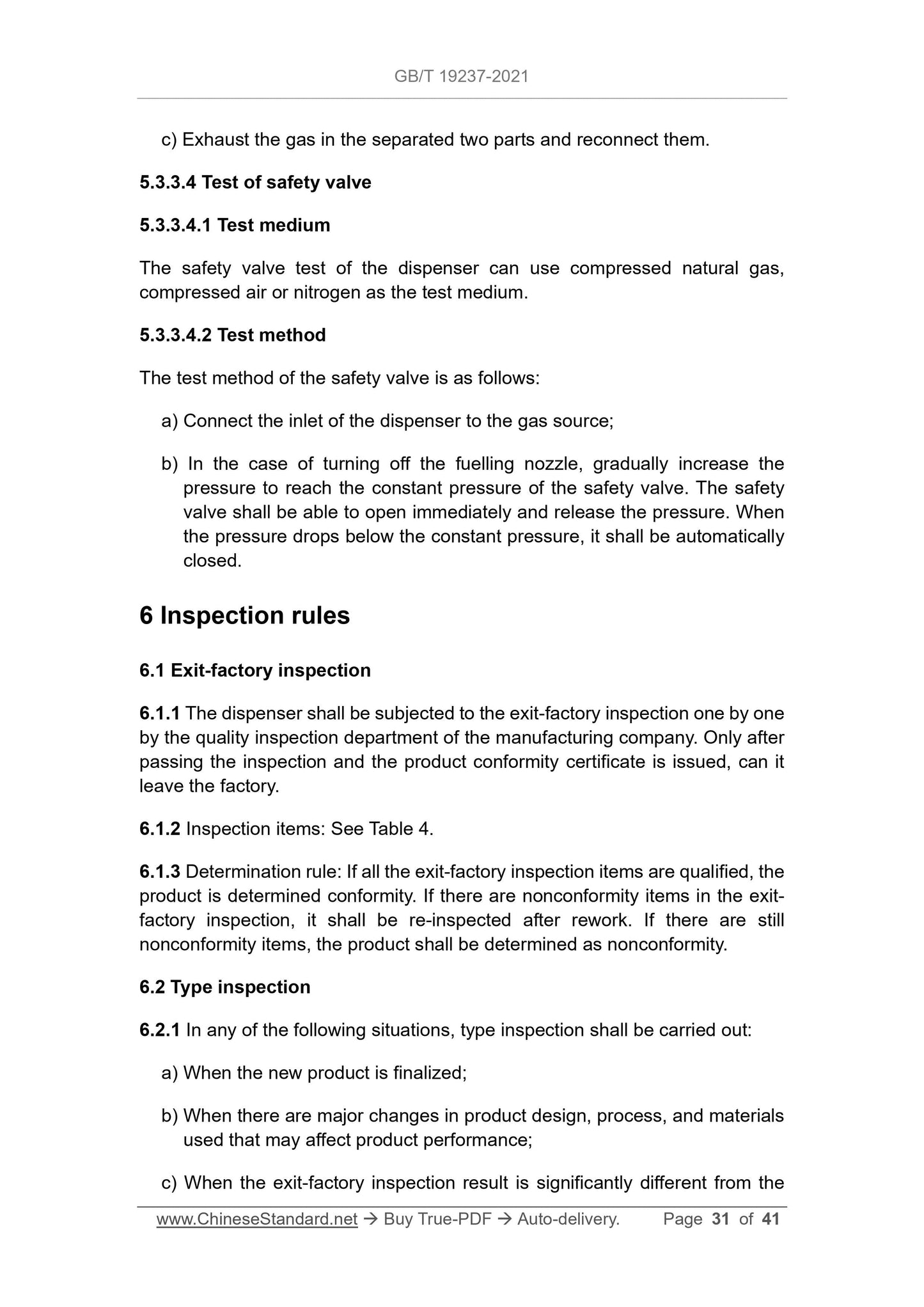
4.4.3.3.4 The two parts, which the breakaway valve is automatically divided into
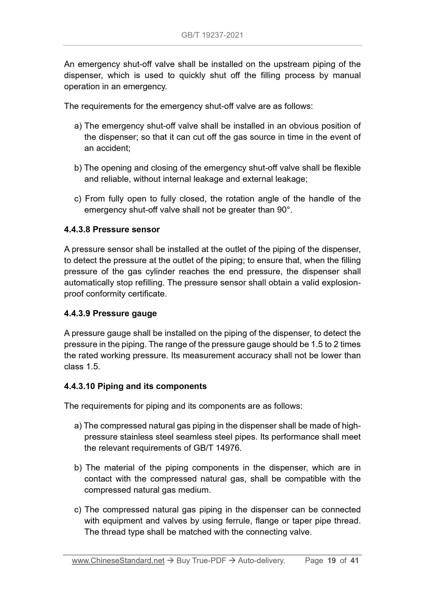
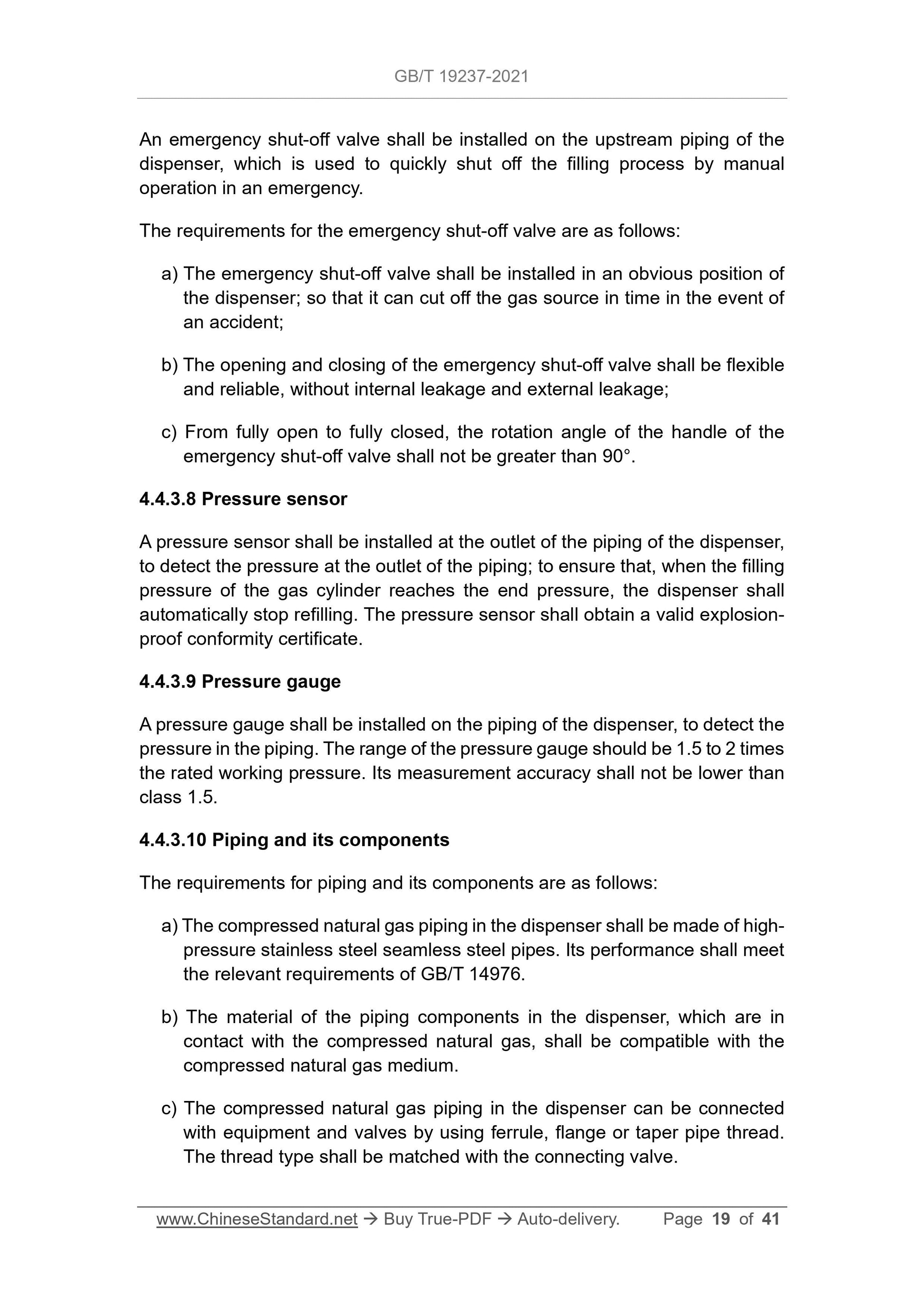
An emergency shut-off valve shall be installed on the upstream piping of the
dispenser, which is used to quickly shut off the filling process by manual
operation in an emergency.
The requirements for the emergency shut-off valve are as follows:
a) The emergency shut-off valve shall be installed in an obvious position of
the dispenser; so that it can cut off the gas source in time in the event of
an accident;
b) The opening and closing of the emergency shut-off valve shall be flexible
and reliable, without internal leakage and external leakage;
c) From fully open to fully closed, the rotation angle of the handle of the
emergency shut-off valve shall not be greater than 90°.
4.4.3.8 Pressure sensor
A pressure sensor shall be installed at the outlet of the piping of the dispenser,
to detect the pressure at the outlet of the piping; to ensure that, when the filling
pressure of the gas cylinder reaches the end pressure, the dispenser shall
automatically stop refilling. The pressure sensor shall obtain a valid explosion-
proof conformity certificate.
4.4.3.9 Pressure gauge
A pressure gauge shall be installed on the piping of the dispenser, to detect the
pressure in the piping. The range of the pressure gauge should be 1.5 to 2 times
the rated working pressure. Its measurement accuracy shall not be lower than
class 1.5.
4.4.3.10 Piping and its components
The requirements for piping and its components are as follows:
a) The compressed natural gas piping in the dispenser shall be made of high-
pressure stainless steel seamless steel pipes. Its performance shall meet
the relevant requirements of GB/T 14976.
b) The material of the piping components in the dispenser, which are in
contact with the compressed natural gas, shall be compatible with the
compressed natural gas medium.
c) The compressed natural gas piping in the dispenser can be connected
with equipment and valves by using ferrule, flange or taper pipe thread.
The thread type shall be matched with the connecting valve.
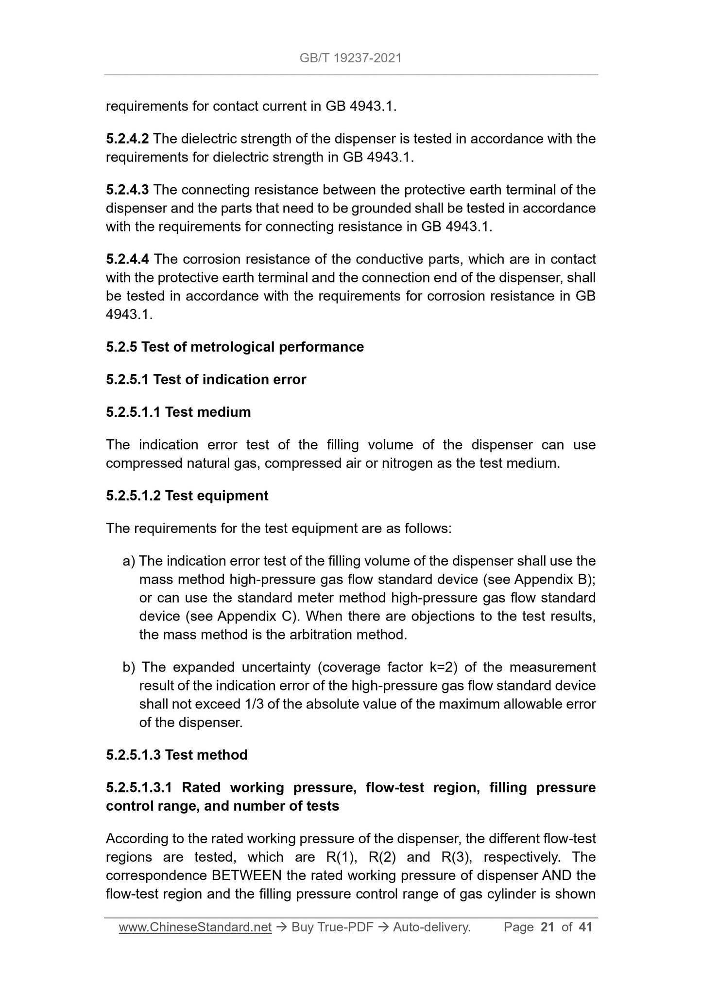
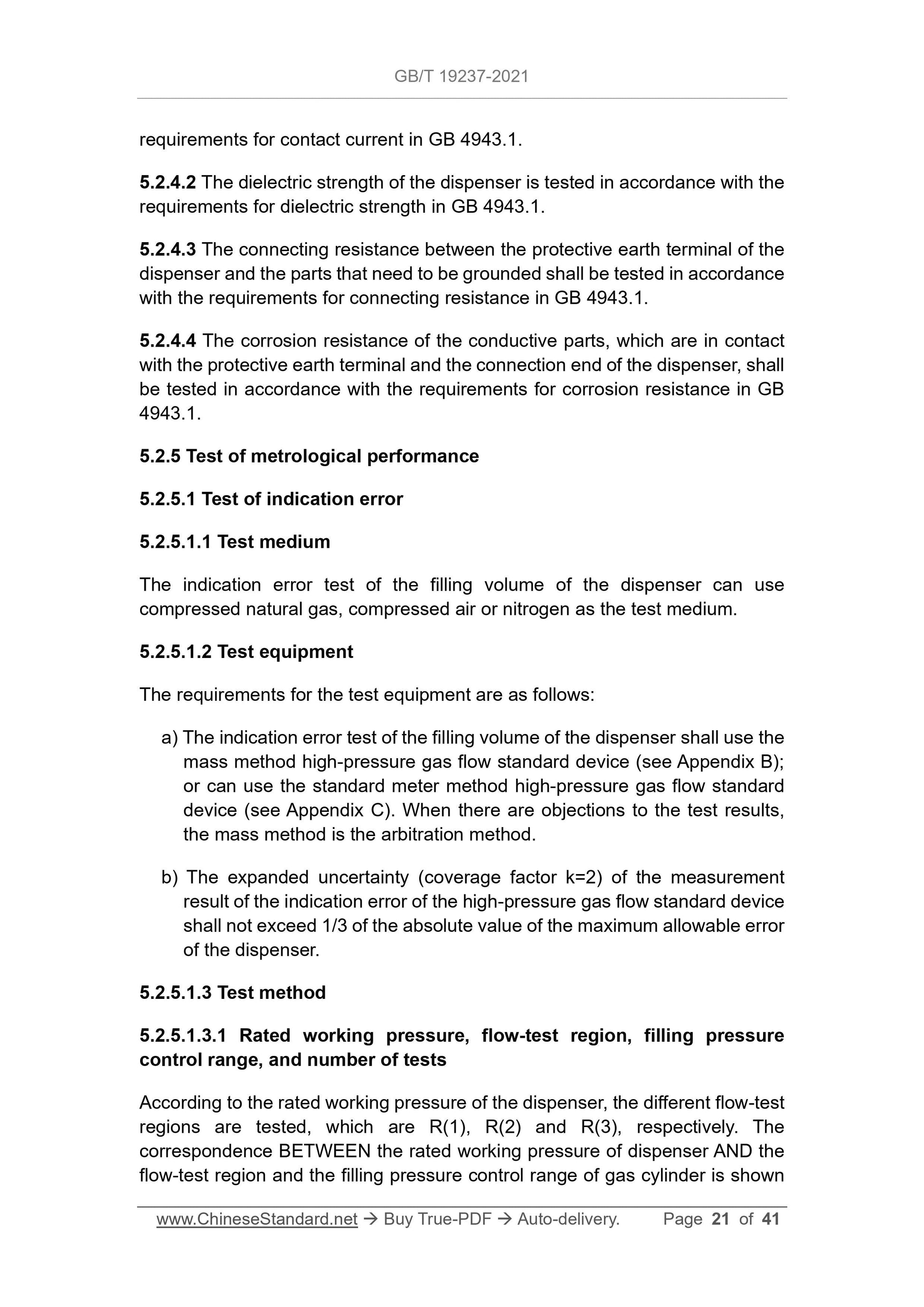
requirements for contact current in GB 4943.1.
5.2.4.2 The dielectric strength of the dispenser is tested in accordance with the
requirements for dielectric strength in GB 4943.1.
5.2.4.3 The connecting resistance between the protective earth terminal of the
dispenser and the parts that need to be grounded shall be tested in accordance
with the requirements for connecting resistance in GB 4943.1.
5.2.4.4 The corrosion resistance of the conductive parts, which are in contact
with the protective earth terminal and the connection end of the dispenser, shall
be tested in accordance with the requirements for corrosion resistance in GB
4943.1.
5.2.5 Test of metrological performance
5.2.5.1 Test of indication error
5.2.5.1.1 Test medium
The indication error test of the filling volume of the dispenser can use
compressed natural gas, compressed air or nitrogen as the test medium.
5.2.5.1.2 Test equipment
The requirements for the test equipment are as follows:
a) The indication error test of the filling volume of the dispenser shall use the
mass method high-pressure gas flow standard device (see Appendix B);
or can use the standard meter method high-pressure gas flow standard
device (see Appendix C). When there are objections to the test results,
the mass method is the arbitration method.
b) The expanded uncertainty (coverage factor k=2) of the measurement
result of the indication error of the high-pressure gas flow standard device
shall not exceed 1/3 of the absolute value of the maximum allowable error
of the dispenser.
5.2.5.1.3 Test method
5.2.5.1.3.1 Rated working pressure, flow-test region, filling pressure
control range, and number of tests
According to the rated working pressure of the dispenser, the different flow-test
regions are tested, which are R(1), R(2) and R(3), respectively. The
correspondence BETWEEN the rated working pressure of dispenser AND the
flow-test region and the filling pressure control range of gas cylinder is shown
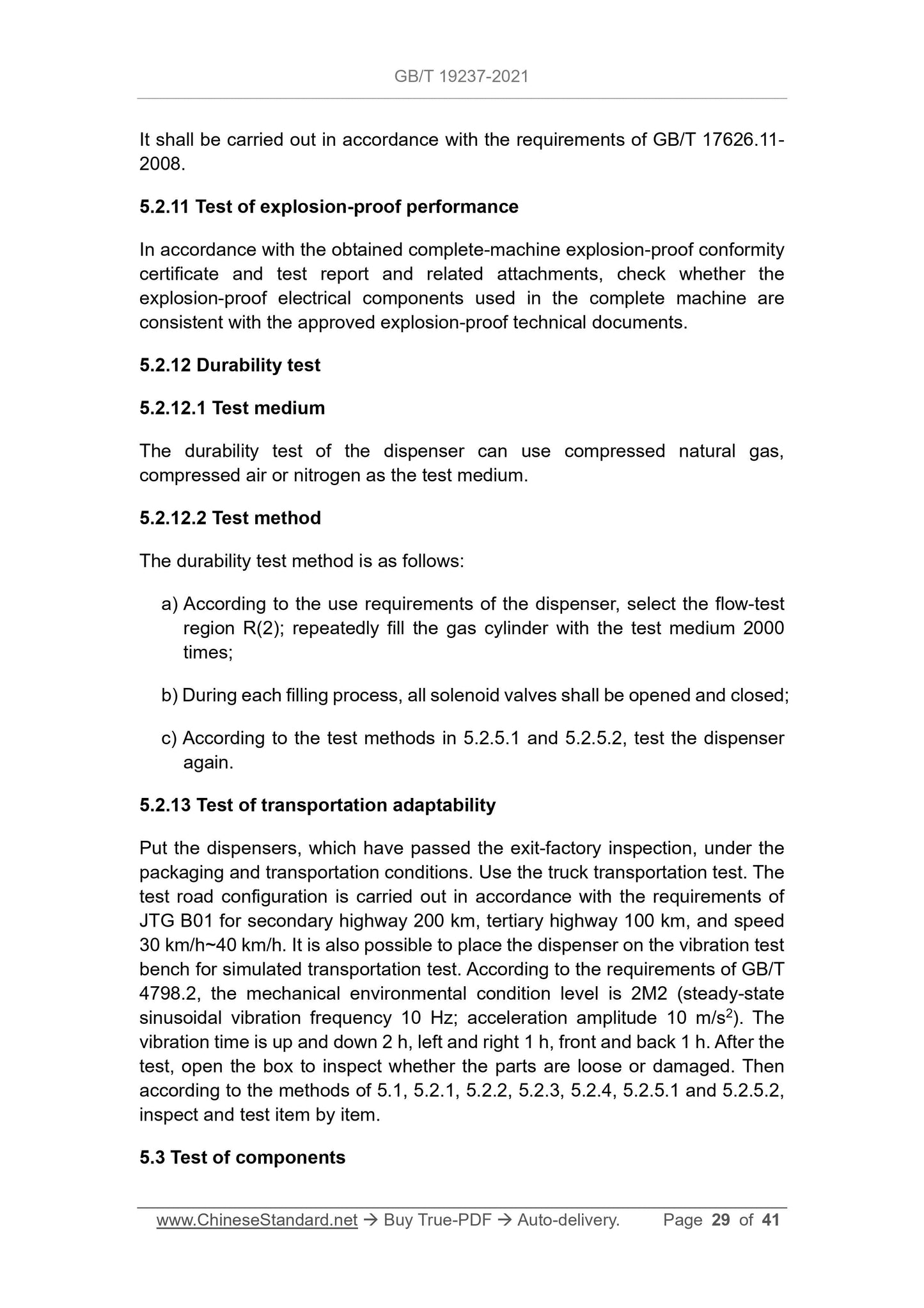
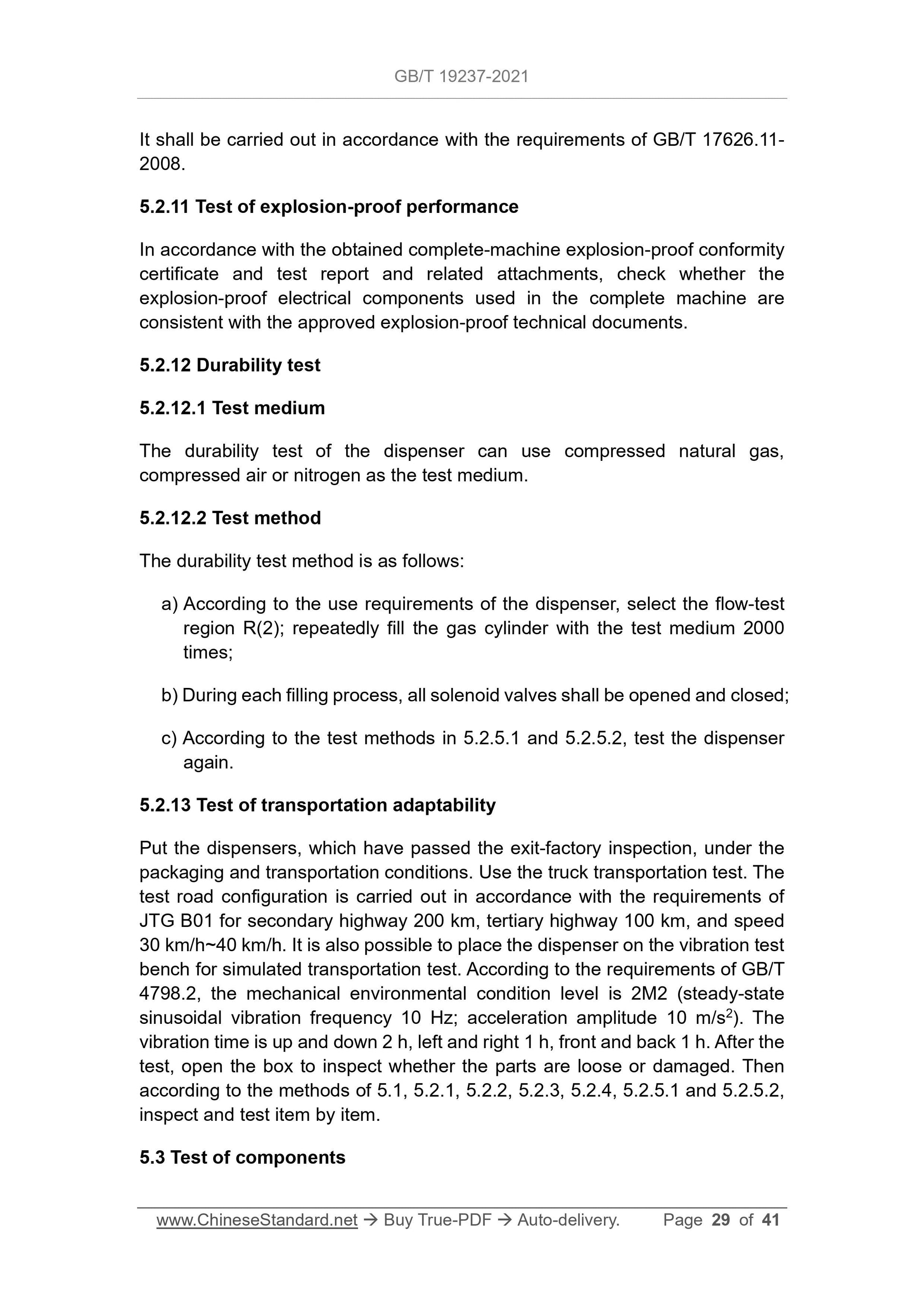
It shall be carried out in accordance with the requirements of GB/T 17626.11-
2008.
5.2.11 Test of explosion-proof performance
In accordance with the obtained complete-machine explosion-proof conformity
certificate and test report and related attachments, check whether the
explosion-proof electrical components used in the com...
Share