GB/T 18655-2018 English PDF (GBT18655-2018)
Regular price
$305.00 USD
Regular price
Sale price
$305.00 USD
Unit price
/
per
Delivery: 3 seconds. Download true-PDF + Invoice.
Get QUOTATION in 1-minute: Click GB/T 18655-2018
Historical versions: GB/T 18655-2018
Preview True-PDF (Reload/Scroll if blank)
GB/T 18655-2018: Vehicles, boats and internal combustion engines -- Radio disturbance characteristics -- Limits and methods of measurement for the protection of on-board receivers
GB/T 18655-2018
Vehicles, boats and internal combustion engines--Radio disturbance characteristics--Limits and methods of measurement for the protection of on-board receivers
ICS 33.100
L06
National Standards of People's Republic of China
Replace GB/T 18655-2010
Radio disturbance characteristics of vehicles, boats and internal combustion engines
Limits and measurement methods for protecting on-board receivers
(CISPR25..2016, MOD)
Published on.2018-07-13
Implementation of.2019-02-01
State Market Supervisory Administration
China National Standardization Administration issued
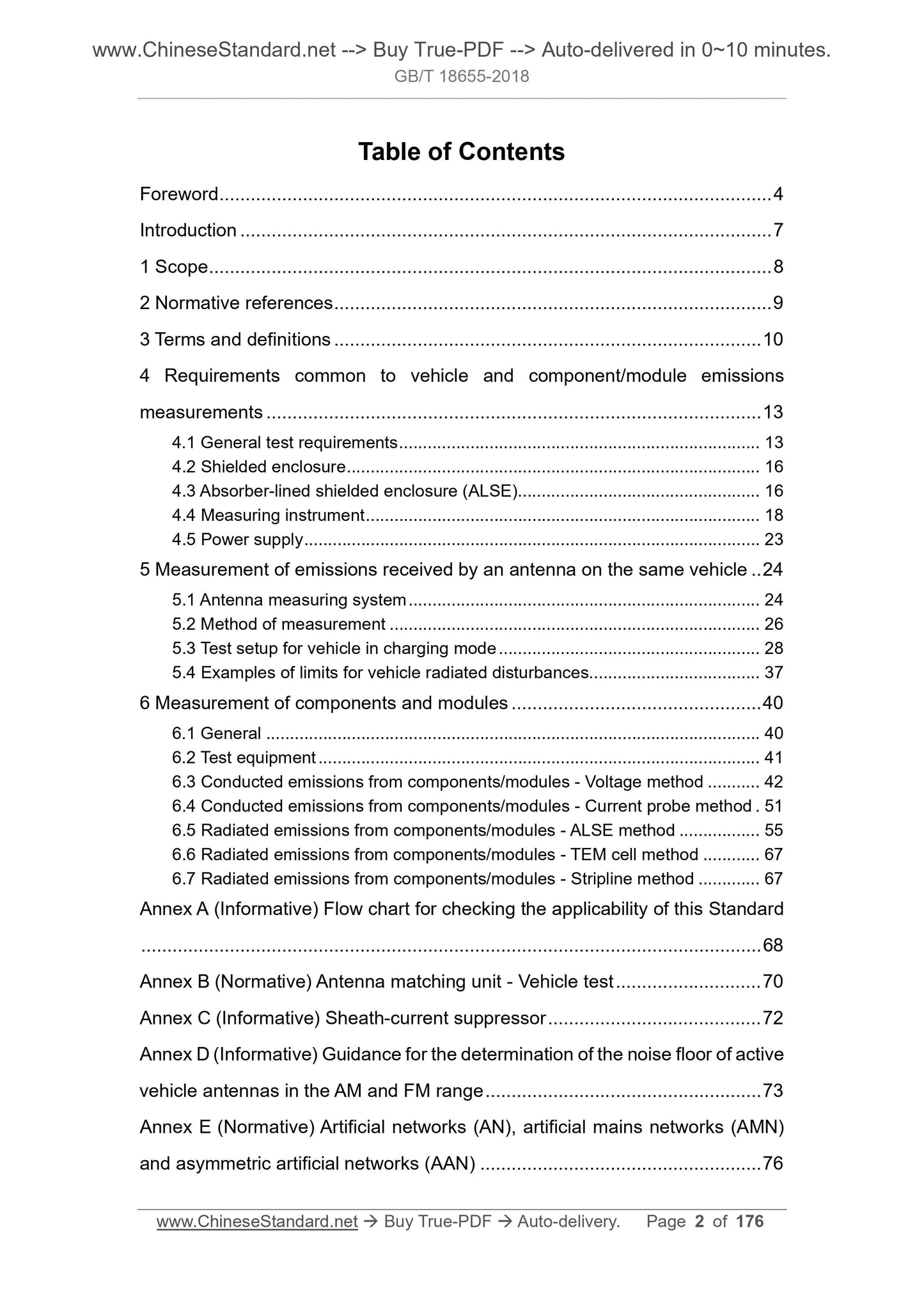
Content
Foreword V
Introduction VII
1 range 1
2 Normative references 1
3 Terms and Definitions 2
4 General requirements for vehicle and component/module emission measurements 4
4.1 General test requirements 4
4.2 Shielding room 6
4.3 Shielded room (ALSE) with absorbing material 6
4.4 Measuring instrument 7
4.5 Power supply 10
5 Emission measurement received by the vehicle antenna 10
5.1 Antenna Measurement System 10
5.2 Measurement method 12
5.3 Test arrangement in vehicle charging mode 13
5.4 Examples of limits for vehicle radiated disturbances 21
6 Measurement of parts and modules 23
6.1 General requirements 23
6.2 Test equipment 24
6.3 Conducted emissions of components/modules---Voltage method 24
6.4 Conducted emission of components/modules---current probe method 31
6.5 Radiation Emissions of Parts/Modules---ALSE Method 34
6.6 Radiation Emissions of Parts/Modules---TEM Chamber Method 43
6.7 Radiation Emissions of Parts/Modules---Stripline Method 43
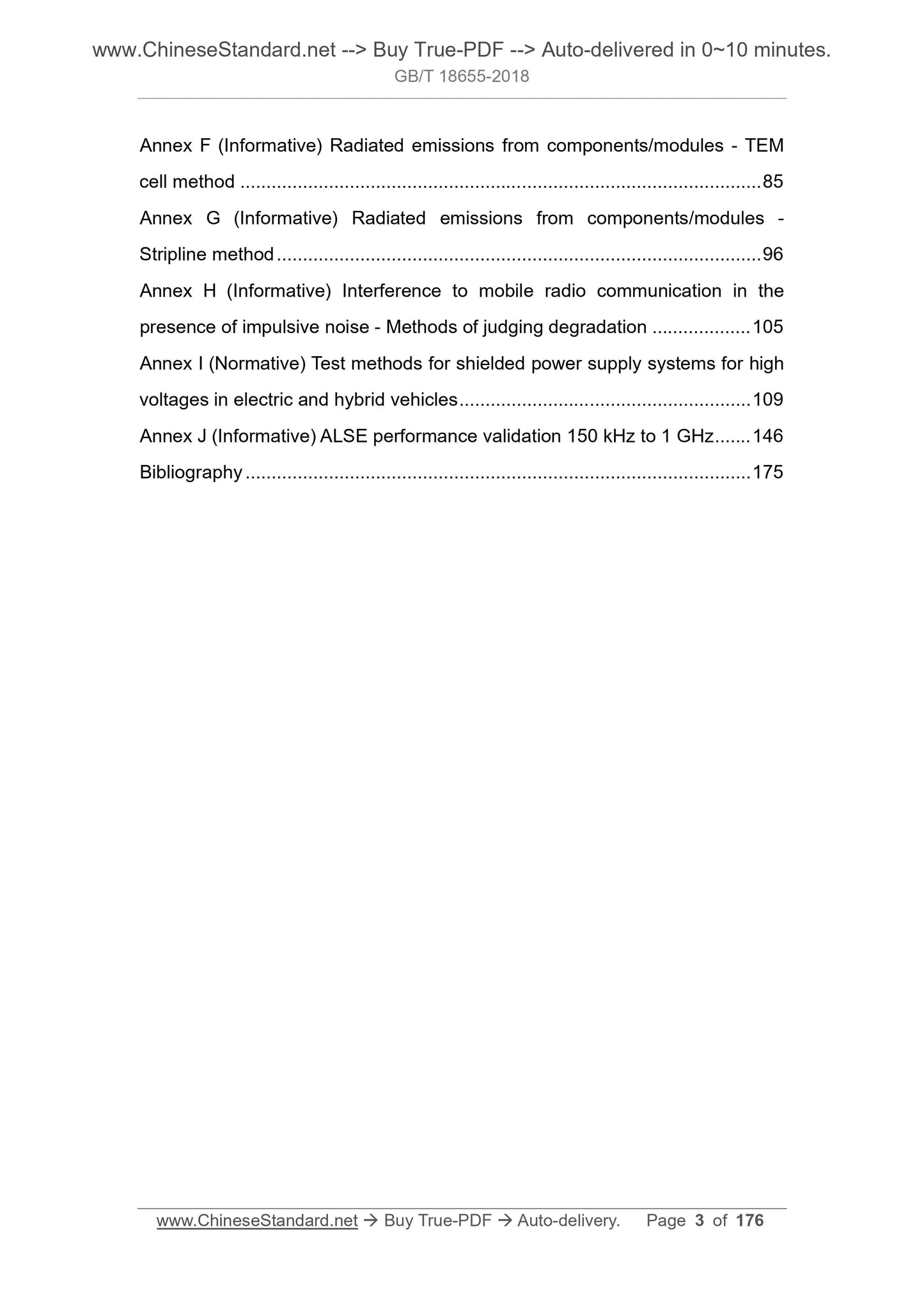
Appendix A (informative appendix) Flow chart of applicability check of this standard 44
Appendix B (Normative Appendix) Antenna Matching Unit---Vehicle Test 45
Appendix C (informative) Surface current suppressor 47
Appendix D (informative) Guidelines for determining the noise floor of active vehicle antennas in the AM and FM bands 48
Appendix E (Normative) Artificial Network (AN), Artificial Power Network (AMN), and Asymmetric Artificial Network (AAN) 50
Appendix F (informative) Radiation emission of components/modules---TEM cell method 57
Appendix G (informative) Radiation emission of components/modules---stripline method 65
Appendix H (informative) Interference of the presence of impulse noise on mobile wireless communications---Methods for judging degradation 71
Appendix I (Normative) Test methods for high voltage power systems for shielded electric and hybrid vehicles 74
Appendix J (informative) ALSE performance verification (150kHz~1GHz) 100
Reference 121
Figure 1 Method for judging conformity of all frequency bands 5
Figure 2 Gain curve example 12
Figure 3 Example of vehicle radiation emission test arrangement (view using monopole antenna) 13
Figure 4 Example of vehicle test arrangement of vehicle socket on the side of the vehicle body (AC charging without communication) 15
Figure 5 Example of vehicle test arrangement of vehicle socket in front/rear of vehicle body (AC charging without communication) 16
Figure 6 Example of vehicle test arrangement of vehicle socket on the side of the vehicle body (AC or DC charging with communication) 19
Figure 7 Example of vehicle test arrangement of vehicle socket in front/rear of vehicle body (AC or DC charging with communication) 20
Figure 8 Average value of the average radiated disturbance of the satellite in the satellite positioning band 22
Figure 9 Conducted Emissions---Test Placement Example of Tested Part Grounded at the Remote End of Power Loop
Fig. 10 Conducted emission---Testing arrangement of the test piece grounded at the near end of the power return line
Figure 11 Conducted Emissions---Generator Test Arrangement Example 28
Figure 12 Conducted Emissions---Ignition System Parts Test Arrangement Example 29
Figure 13 Conducted Emissions - Current Probe Test Arrangement Example 32
Figure 14 Test harness bending requirements 35
Figure 15 Example of test arrangement - monopole antenna 37
Figure 16 Example of test arrangement - double cone antenna 38
Figure 17 Example of test arrangement --- logarithmic period antenna 39
Figure 18 Example of test arrangement - above -1GHz 40
Figure 19 Example of component/module radiated disturbance average limit 42
Figure A.1 Flow chart of this standard suitability check 44
Figure B.1 Verification Arrangement 46
Figure C.1 S21 characteristic curve of ferrite magnetic ring 47
Figure D.1 Vehicle layout for measuring equipment noise in the AM/FM band 48
Figure D.2 Vehicle layout for measuring AM/FM band antenna noise 49
Figure E.1 5μH Artificial Network (AN) Schematic Example 50
Figure E.2 Impedance characteristics of the artificial network (AN) ZPB 51
Figure E.3 Schematic example of a 5μH high voltage artificial network (HV-AN) schematic 52
Figure E.4 Example of a single 5μH high voltage artificial network (HV-AN) sharing a shielded enclosure 52
Figure E.5 Impedance matching network between HV-AN and the device under test 53
Figure E.6 AAN example 54 for symmetric communication lines
Figure E.7 Example of AAN Circuitry for PLC on AC or DC Power Lines 55
Figure E.8 Example of AAN Circuit Diagram for PLC on Guide Line 56
Figure F.1 TEM cell (example) 57
Figure F.2 TEM cell lead and example to the interface board lead layout 58
Figure F.3 Example of Arrangement of Connectors, Terminal Blocks, and Insulation Brackets 59
Figure F.4 Example of Minimum Attenuation Value Required for Control/Signal Lines 60
Figure F.5 Filter attenuation measurement arrangement 60
Figure F.6 Example of TEM cell test setup 61
Figure F.7 TEM cell 63
Figure G.1 Shielded indoor stripline test arrangement legend 67
Figure G.2 50Ω stripline example 69
Figure G.3 90Ω stripline example 70
Figure I.1 Conducted Emissions---Example of Test Arrangement of Tested Parts with Shielded Power System 76
Figure I.2 Conducted Emissions---Example of Test Arrangement of Tested Parts with Shielded Power System and Motor Placed on the Rack 77
Figure I.3 Conducted Emissions - Example of Inverter Test Arrangement with Shielded Power System 78
Figure I.4 Conducted Emissions - Example of a Charger Test Arrangement with Shielded Power System 79
Figure I.5 Conducted Emissions--Example of a test arrangement for measuring the HV line of the device under test with a shielded power system using a current probe 83
Figure I.6 Conducted Emissions---Testing the HV line of the device under test with a shielded power system and the motor placed on the pedestal using a current probe
Inspection arrangement example 84
Figure I.7 Conducted Emissions - Example of a test arrangement for measuring an inverter HV line with a shielded power system using a current probe 85
Figure I.8 Conducted Emissions - Example of a test arrangement for measuring a HV line of a charger with a shielded power system using a current probe 86
Figure I.9 Radiated Emissions - Example of a test arrangement for a DUT with a shielded power system using a biconical antenna
Figure I.10 Radiated Emissions---Tests with Shielded Power Systems, Tested Parts with Motors Attached to the Bench Using a Double Cone Antenna
Layout example 89
Figure I.11 Radiated Emissions - Example of a test arrangement for an inverter with a shielded power system using a biconical antenna
Figure I.12 Radiated Emissions – Example of a test arrangement for a charger with a shielded power system using a biconical antenna
Figure I.13 Test arrangement for test signal calibration 93
Figure I.14 Conducted Emission---Voltage Method---Experimental Arrangement Example ...