Skip to product information
1 of 7

PayPal, credit cards. Download editable-PDF and invoice in 1 second!

GB/T 18655-2010 English PDF (GBT18655-2010)

GB/T 18655-2010 English PDF (GBT18655-2010)

Regular price $170.00 USD
Regular price Sale price $170.00 USD
Sale Sold out
Shipping calculated at checkout.
Delivery: 3 seconds. Download true-PDF + Invoice.Newer version: (Replacing this standard) GB/T 18655-2018
Get QUOTATION in 1-minute: Click GB/T 18655-2010
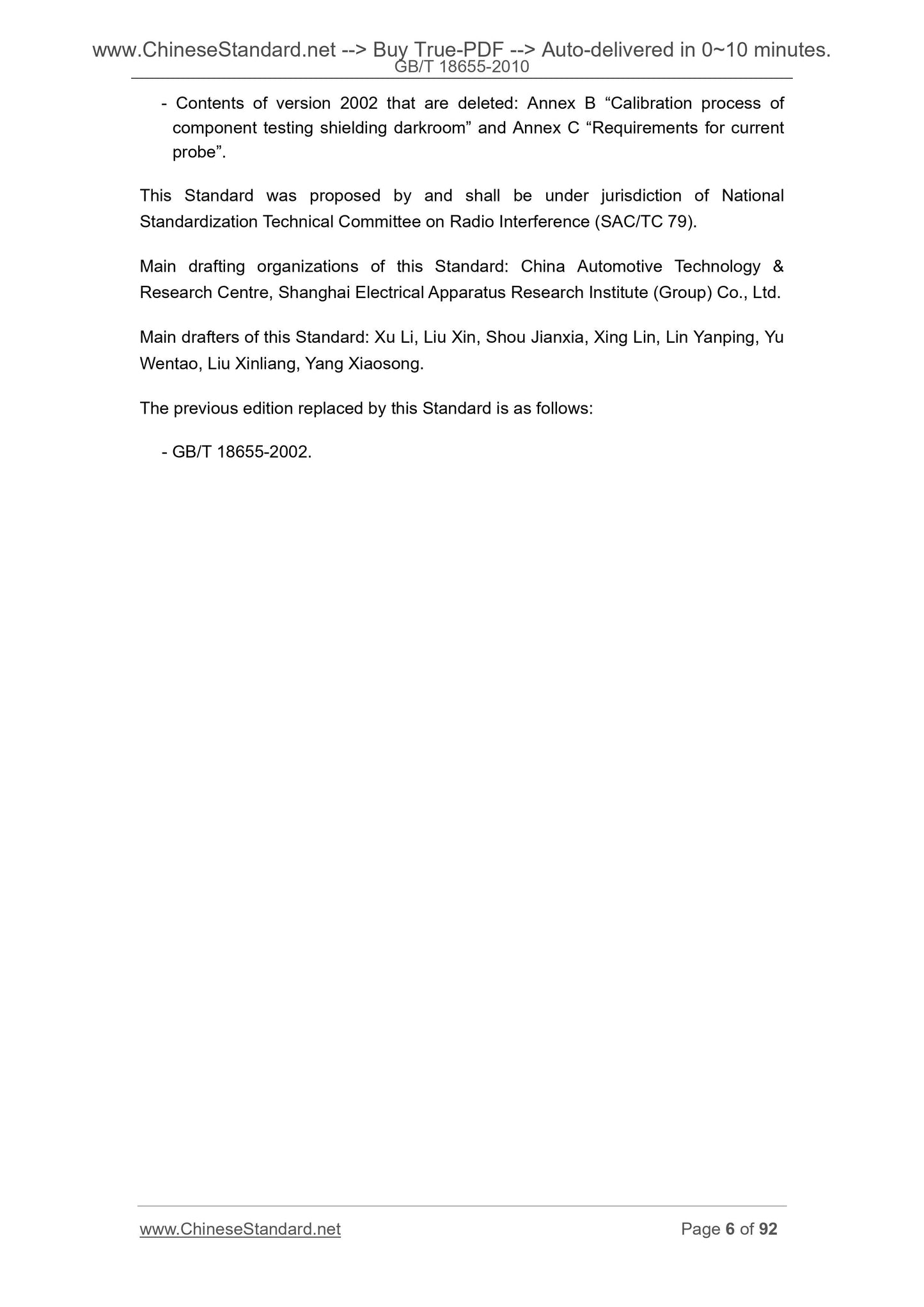
Historical versions: GB/T 18655-2010
Preview True-PDF (Reload/Scroll if blank)

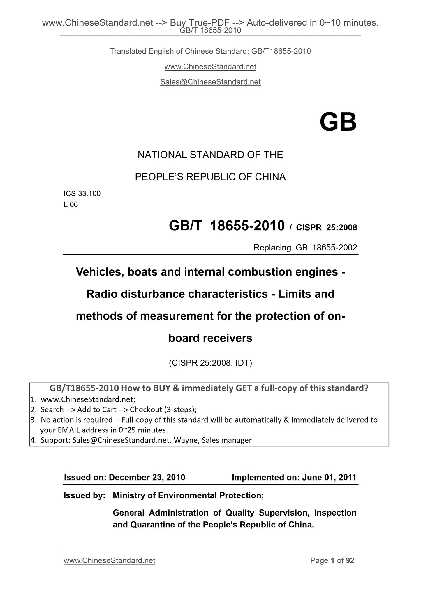
GB/T 18655-2010: Vehicles, boats and internal combustion engines -- Radio disturbance characteristics -- Limits and methods of measurement for the protection of on-board receivers
GB/T 18655-2010 
GB
NATIONAL STANDARD OF THE
PEOPLE’S REPUBLIC OF CHINA
ICS 33.100
L 06
GB/T 18655-2010 / CISPR 25.2008
Replacing GB 18655-2002
Vehicles, boats and internal combustion engines -
Radio disturbance characteristics - Limits and
methods of measurement for the protection of on-
board receivers
(CISPR 25.2008, IDT)
ISSUED ON. DECEMBER 23, 2010
IMPLEMENTED ON. JUNE 01, 2011
Issued by.
Ministry of Environmental Protection;
General Administration of Quality Supervision, Inspection
and Quarantine of the People’s Republic of China.
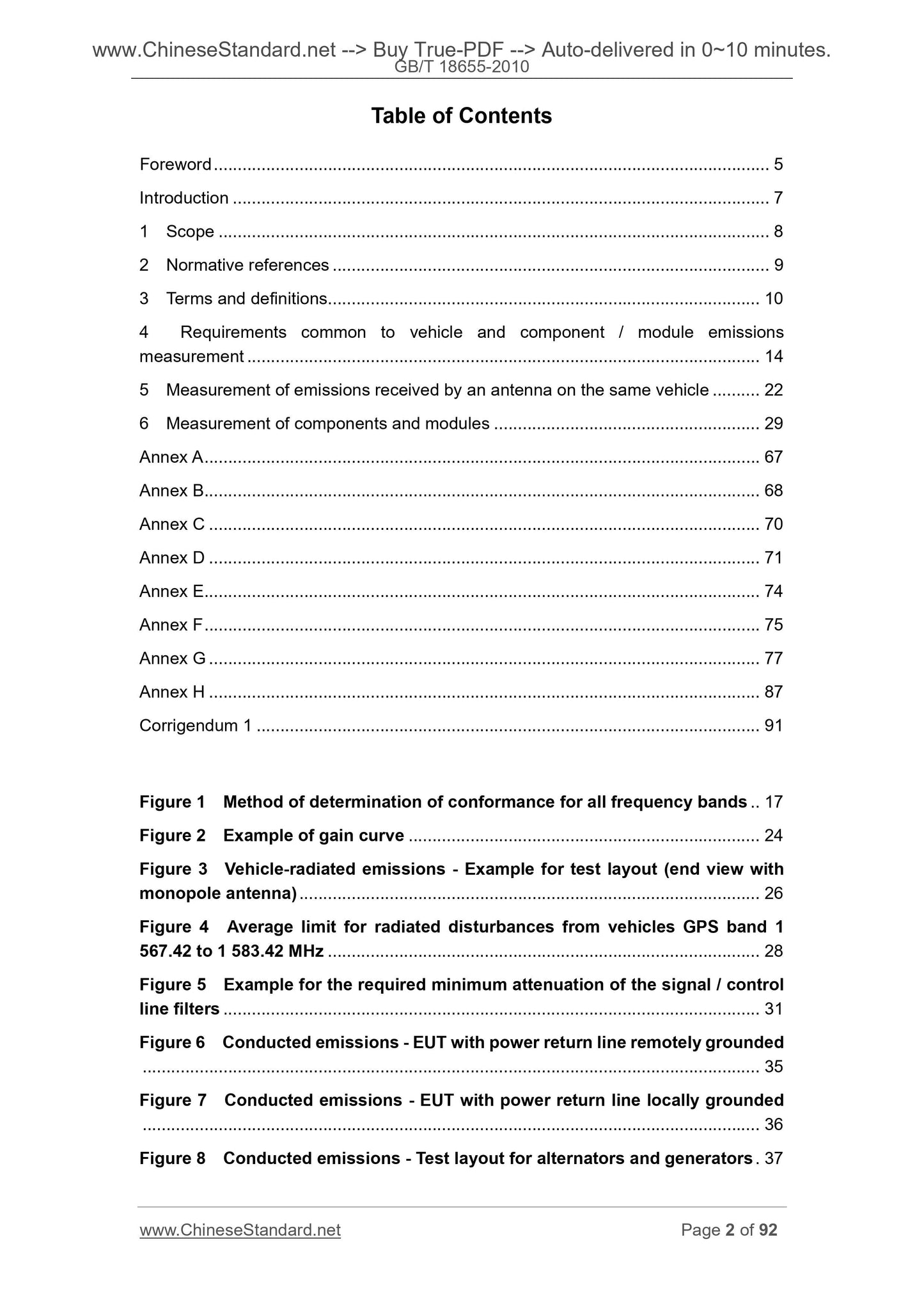
Table of Contents
Foreword ... 5 
Introduction ... 7 
1 Scope ... 8 
2 Normative references ... 9 
3 Terms and definitions ... 10 
4 Requirements common to vehicle and component / module emissions
measurement ... 14 
5 Measurement of emissions received by an antenna on the same vehicle ... 22 
6 Measurement of components and modules ... 29 
Annex A ... 67 
Annex B... 68 
Annex C ... 70 
Annex D ... 71 
Annex E... 74 
Annex F ... 75 
Annex G ... 77 
Annex H ... 87 
Corrigendum 1 ... 91 
Figure 1 Method of determination of conformance for all frequency bands .. 17 
Figure 2 Example of gain curve ... 24 
Figure 3 Vehicle-radiated emissions - Example for test layout (end view with
monopole antenna) ... 26 
Figure 4 Average limit for radiated disturbances from vehicles GPS band 1
567.42 to 1 583.42 MHz ... 28 
Figure 5 Example for the required minimum attenuation of the signal / control
line filters ... 31 
Figure 6 Conducted emissions - EUT with power return line remotely grounded
... 35 
Figure 7 Conducted emissions - EUT with power return line locally grounded
... 36 
Figure 8 Conducted emissions - Test layout for alternators and generators . 37 
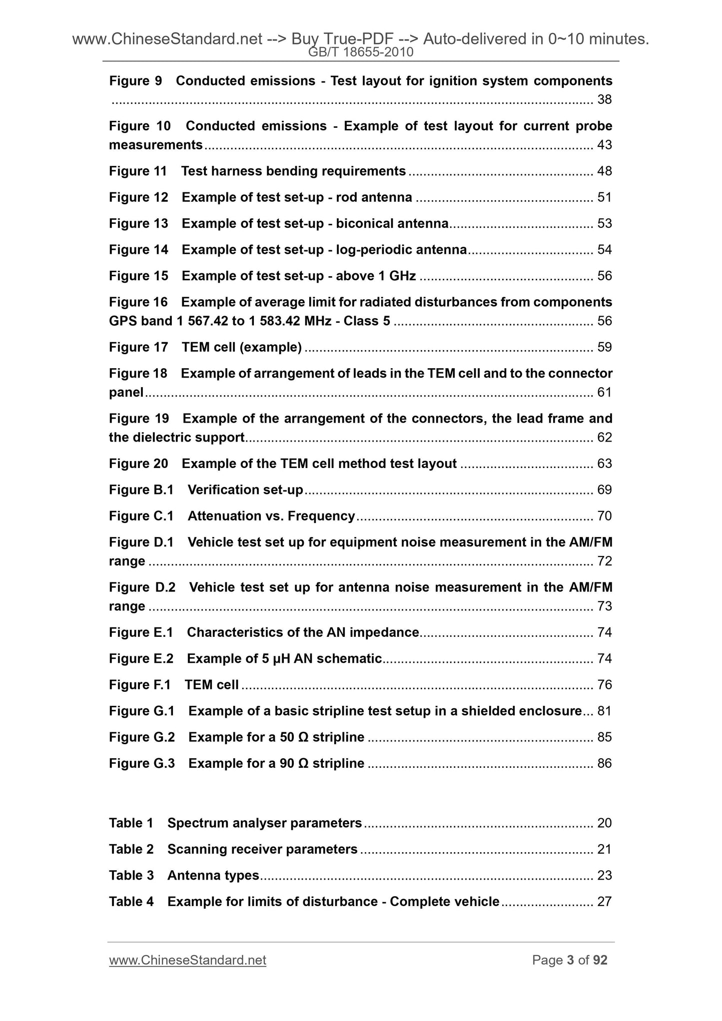
Figure 9 Conducted emissions - Test layout for ignition system components
... 38 
Figure 10 Conducted emissions - Example of test layout for current probe
measurements ... 43 
Figure 11 Test harness bending requirements ... 48 
Figure 12 Example of test set-up - rod antenna ... 51 
Figure 13 Example of test set-up - biconical antenna ... 53 
Figure 14 Example of test set-up - log-periodic antenna ... 54 
Figure 15 Example of test set-up - above 1 GHz ... 56 
Figure 16 Example of average limit for radiated disturbances from components
GPS band 1 567.42 to 1 583.42 MHz - Class 5 ... 56 
Figure 17 TEM cell (example) ... 59 
Figure 18 Example of arrangement of leads in the TEM cell and to the connector
panel ... 61 
Figure 19 Example of the arrangement of the connectors, the lead frame and
the dielectric support ... 62 
Figure 20 Example of the TEM cell method test layout ... 63 
Figure B.1 Verification set-up ... 69 
Figure C.1 Attenuation vs. Frequency ... 70 
Figure D.1 Vehicle test set up for equipment noise measurement in the AM/FM
range ... 72 
Figure D.2 Vehicle test set up for antenna noise measurement in the AM/FM
range ... 73 
Figure E.1 Characteristics of the AN impedance... 74 
Figure E.2 Example of 5 μH AN schematic... 74 
Figure F.1 TEM cell ... 76 
Figure G.1 Example of a basic stripline test setup in a shielded enclosure ... 81 
Figure G.2 Example for a 50 Ω stripline ... 85 
Figure G.3 Example for a 90 Ω stripline ... 86 
Table 1 Spectrum analyser parameters ... 20 
Table 2 Scanning receiver parameters ... 21 
Table 3 Antenna types ... 23 
Table 4 Example for limits of disturbance - Complete vehicle ... 27 
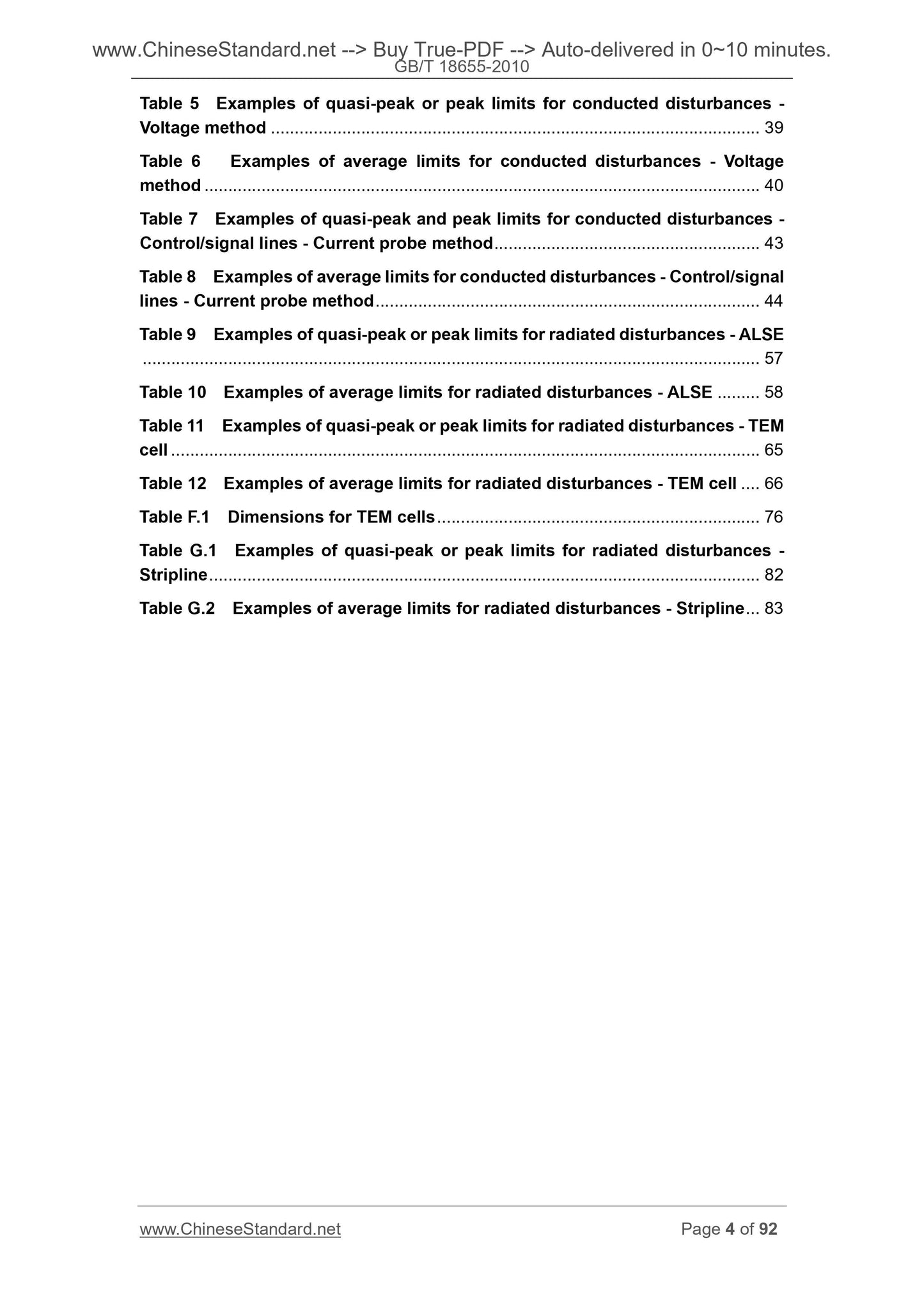
Table 5 Examples of quasi-peak or peak limits for conducted disturbances -
Voltage method ... 39 
Table 6 Examples of average limits for conducted disturbances - Voltage
method ... 40 
Table 7 Examples of quasi-peak and peak limits for conducted disturbances -
Control/signal lines - Current probe method ... 43 
Table 8 Examples of average limits for conducted disturbances - Control/signal
lines - Current probe method ... 44 
Table 9 Examples of quasi-peak or peak limits for radiated disturbances - ALSE
... 57 
Table 10 Examples of average limits for radiated disturbances - ALSE ... 58 
Table 11 Examples of quasi-peak or peak limits for radiated disturbances - TEM
cell ... 65 
Table 12 Examples of average limits for radiated disturbances - TEM cell ... 66 
Table F.1 Dimensions for TEM cells ... 76 
Table G.1 Examples of quasi-peak or peak limits for radiated disturbances -
Stripline ... 82 
Table G.2 Examples of average limits for radiated disturbances - Stripline ... 83 
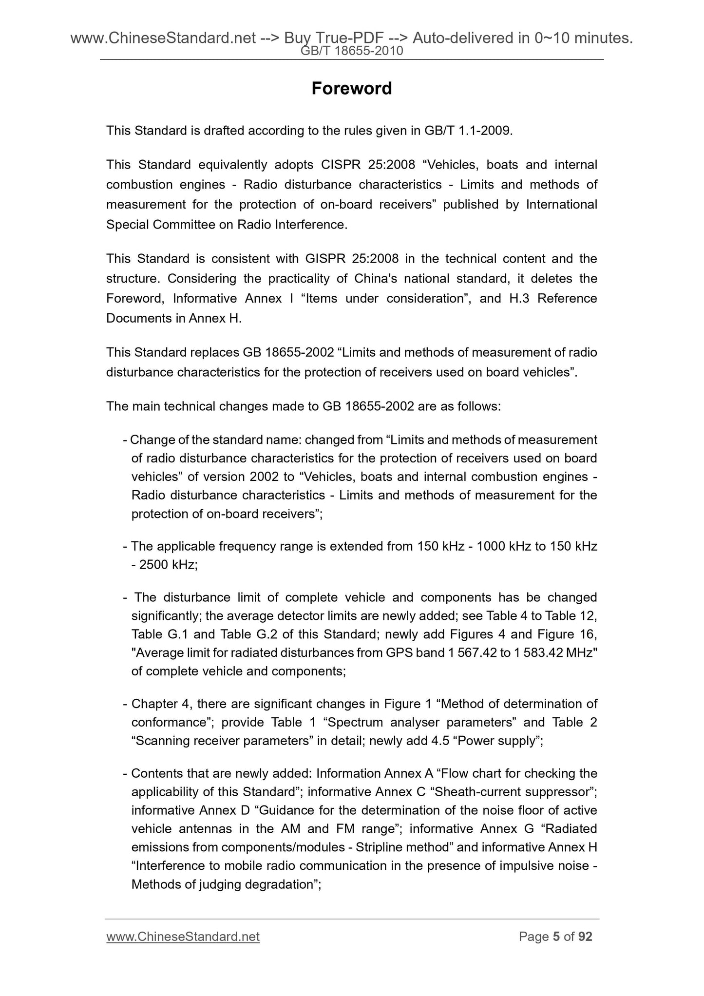
Foreword
This Standard is drafted according to the rules given in GB/T 1.1-2009.
This Standard equivalently adopts CISPR 25.2008 “Vehicles, boats and internal
combustion engines - Radio disturbance characteristics - Limits and methods of
measurement for the protection of on-board receivers” published by International
Special Committee on Radio Interference.
This Standard is consistent with GISPR 25.2008 in the technical content and the
structure. Considering the practicality of China's national standard, it deletes the
Foreword, Informative Annex I “Items under consideration”, and H.3 Reference
Documents in Annex H.
This Standard replaces GB 18655-2002 “Lim...

View full details