Skip to product information
1 of 12

PayPal, credit cards. Download editable-PDF and invoice in 1 second!

GB/T 18604-2023 English PDF (GB/T18604-2023)

GB/T 18604-2023 English PDF (GB/T18604-2023)

Regular price $680.00 USD
Regular price Sale price $680.00 USD
Sale Sold out
Shipping calculated at checkout.
Delivery: 3 seconds. Download true-PDF + Invoice.
Get Quotation: Click GB/T 18604-2023 (Self-service in 1-minute)
Historical versions (Master-website): GB/T 18604-2023
Preview True-PDF (Reload/Scroll-down if blank)

GB/T 18604-2023: Measurement of natural gas flow by gas ultrasonic flow meters
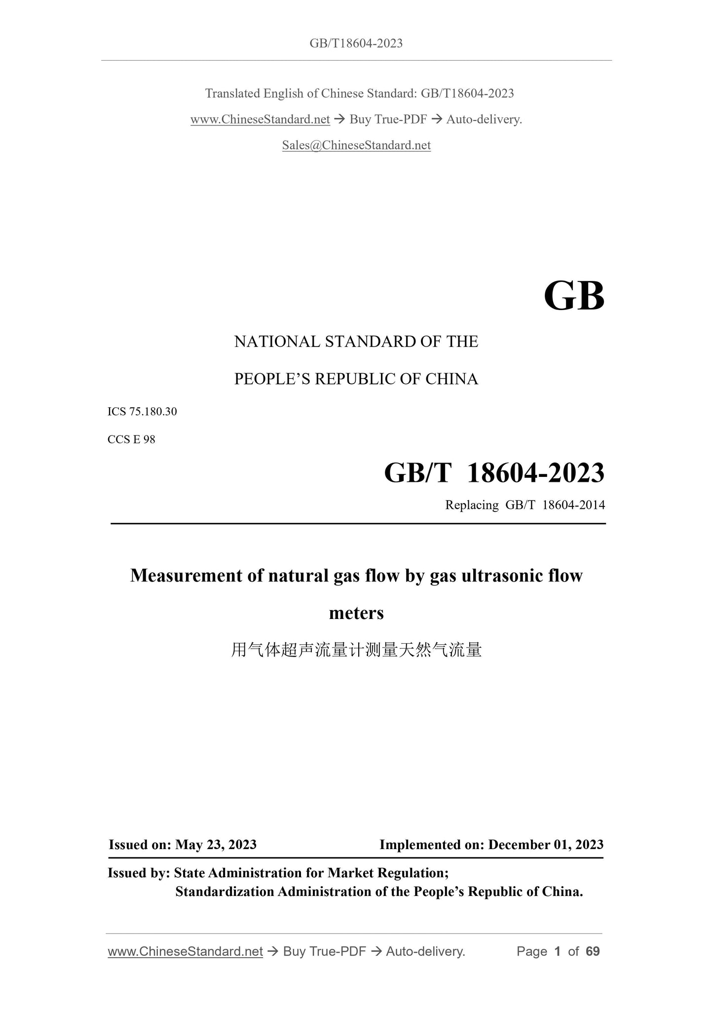
GB/T 18604-2023
GB
NATIONAL STANDARD OF THE
PEOPLE’S REPUBLIC OF CHINA
ICS 75.180.30
CCS E 98
GB/T 18604-2023
Replacing GB/T 18604-2014
Measurement of natural gas flow by gas ultrasonic flow
meters
ISSUED ON: MAY 23, 2023
IMPLEMENTED ON: DECEMBER 01, 2023
Issued by: State Administration for Market Regulation;
Standardization Administration of the People’s Republic of China.
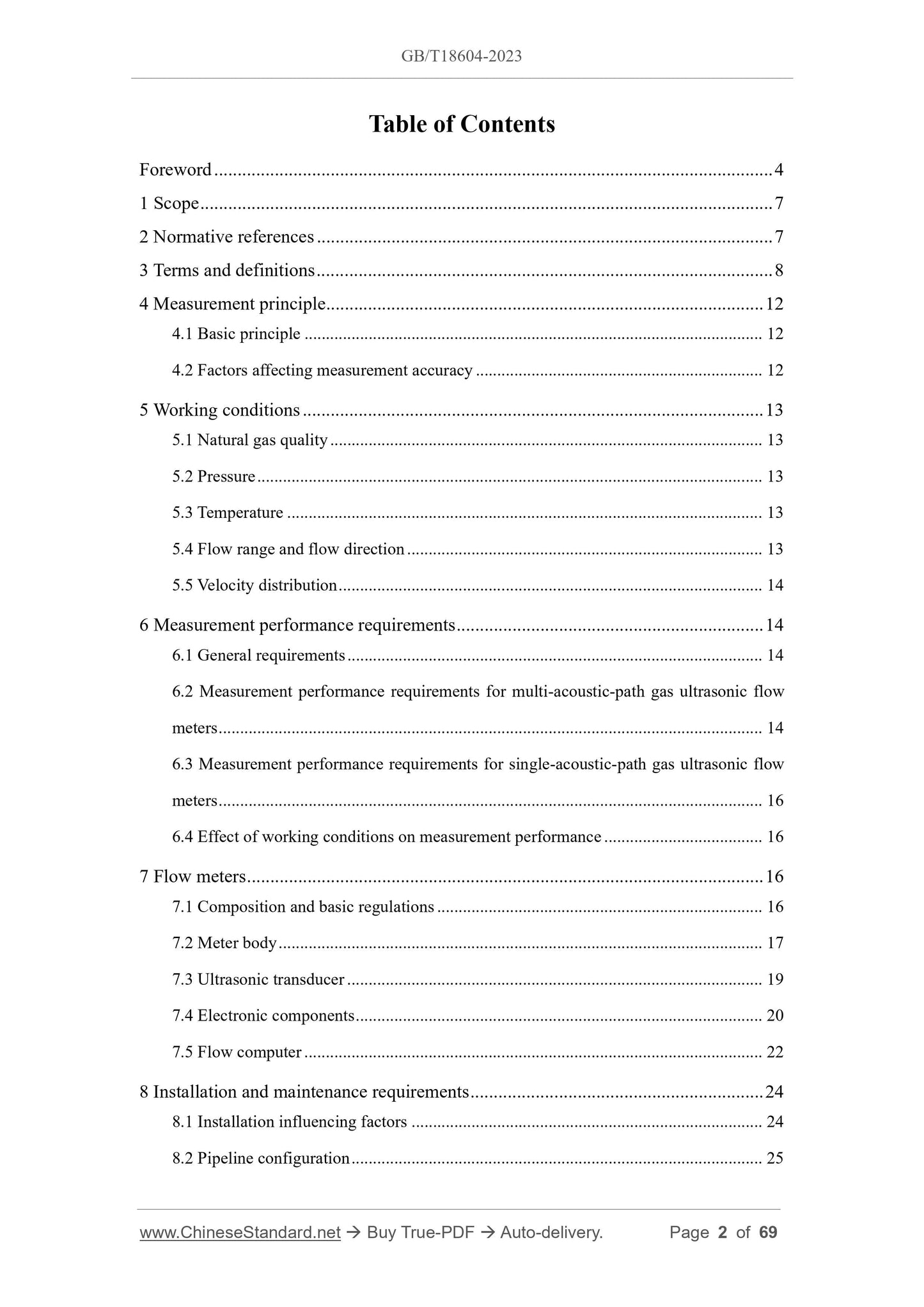
Table of Contents
Foreword ... 4
1 Scope ... 7
2 Normative references ... 7
3 Terms and definitions ... 8
4 Measurement principle ... 12
4.1 Basic principle ... 12
4.2 Factors affecting measurement accuracy ... 12
5 Working conditions ... 13
5.1 Natural gas quality ... 13
5.2 Pressure ... 13
5.3 Temperature ... 13
5.4 Flow range and flow direction ... 13
5.5 Velocity distribution ... 14
6 Measurement performance requirements ... 14
6.1 General requirements ... 14
6.2 Measurement performance requirements for multi-acoustic-path gas ultrasonic flow
meters ... 14
6.3 Measurement performance requirements for single-acoustic-path gas ultrasonic flow
meters ... 16
6.4 Effect of working conditions on measurement performance ... 16
7 Flow meters ... 16
7.1 Composition and basic regulations ... 16
7.2 Meter body ... 17
7.3 Ultrasonic transducer ... 19
7.4 Electronic components ... 20
7.5 Flow computer ... 22
8 Installation and maintenance requirements ... 24
8.1 Installation influencing factors ... 24
8.2 Pipeline configuration ... 25
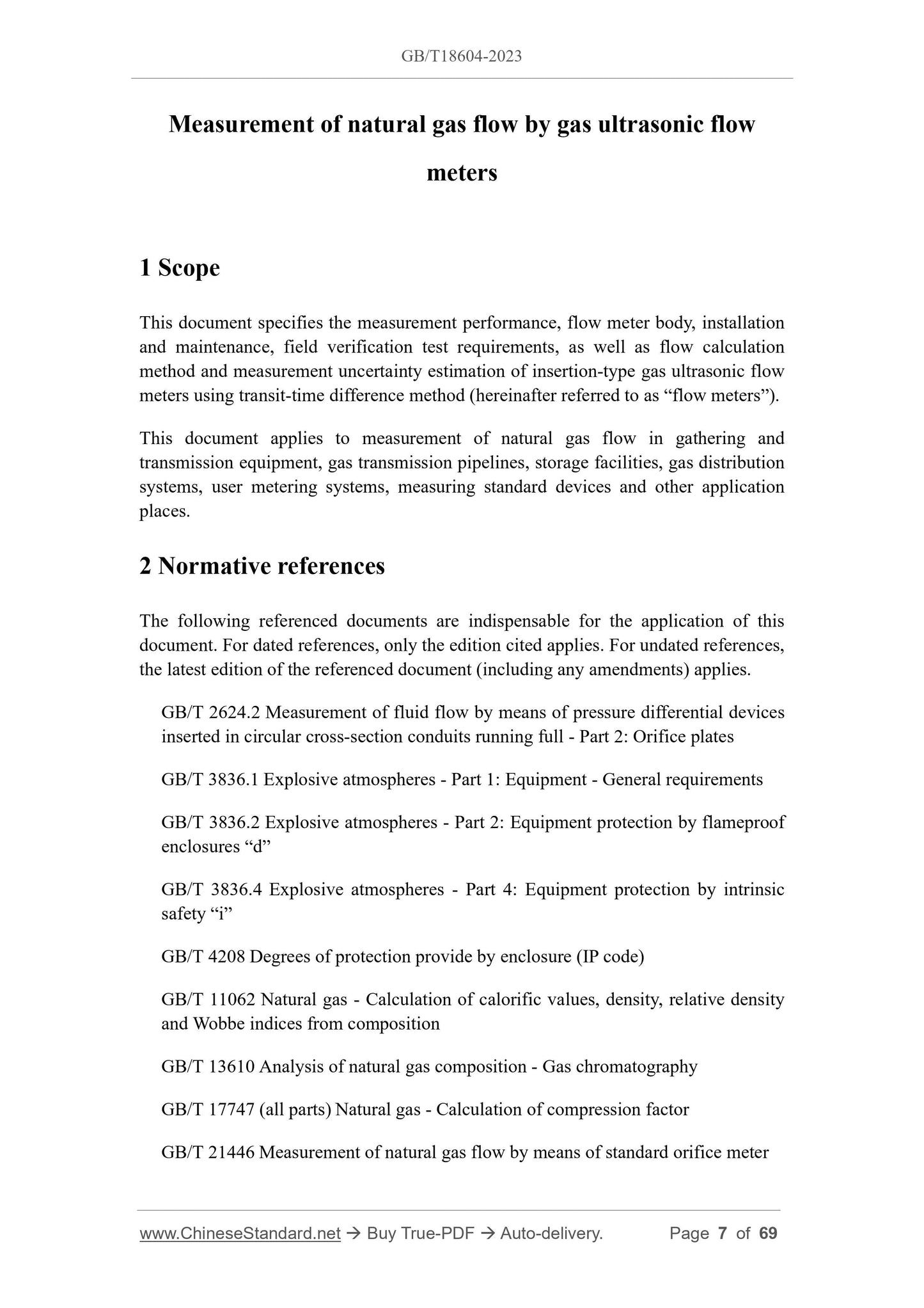
Measurement of natural gas flow by gas ultrasonic flow
meters
1 Scope
This document specifies the measurement performance, flow meter body, installation
and maintenance, field verification test requirements, as well as flow calculation
method and measurement uncertainty estimation of insertion-type gas ultrasonic flow
meters using transit-time difference method (hereinafter referred to as “flow meters”).
This document applies to measurement of natural gas flow in gathering and
transmission equipment, gas transmission pipelines, storage facilities, gas distribution
systems, user metering systems, measuring standard devices and other application
places.
2 Normative references
The following referenced documents are indispensable for the application of this
document. For dated references, only the edition cited applies. For undated references,
the latest edition of the referenced document (including any amendments) applies.
GB/T 2624.2 Measurement of fluid flow by means of pressure differential devices
inserted in circular cross-section conduits running full - Part 2: Orifice plates
GB/T 3836.1 Explosive atmospheres - Part 1: Equipment - General requirements
GB/T 3836.2 Explosive atmospheres - Part 2: Equipment protection by flameproof
enclosures “d”
GB/T 3836.4 Explosive atmospheres - Part 4: Equipment protection by intrinsic
safety “i”
GB/T 4208 Degrees of protection provide by enclosure (IP code)
GB/T 11062 Natural gas - Calculation of calorific values, density, relative density
and Wobbe indices from composition
GB/T 13610 Analysis of natural gas composition - Gas chromatography
GB/T 17747 (all parts) Natural gas - Calculation of compression factor
GB/T 21446 Measurement of natural gas flow by means of standard orifice meter
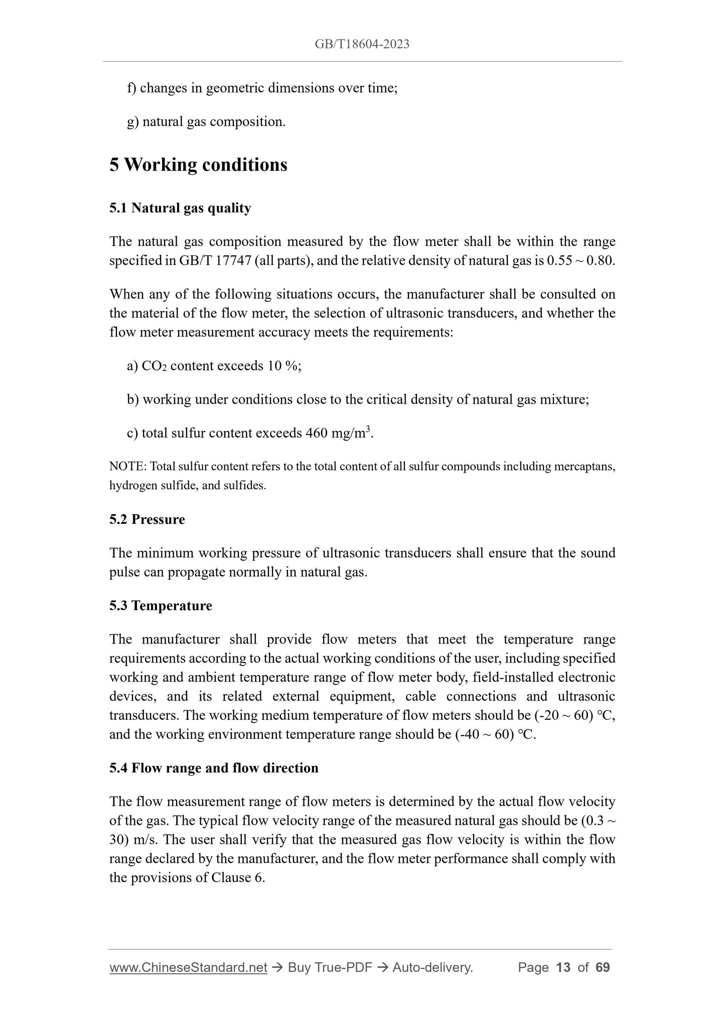
f) changes in geometric dimensions over time;
g) natural gas composition.
5 Working conditions
5.1 Natural gas quality
The natural gas composition measured by the flow meter shall be within the range
specified in GB/T 17747 (all parts), and the relative density of natural gas is 0.55 ~ 0.80.
When any of the following situations occurs, the manufacturer shall be consulted on
the material of the flow meter, the selection of ultrasonic transducers, and whether the
flow meter measurement accuracy meets the requirements:
a) CO2 content exceeds 10 %;
b) working under conditions close to the critical density of natural gas mixture;
c) total sulfur content exceeds 460 mg/m3.
NOTE: Total sulfur content refers to the total content of all sulfur compounds including mercaptans,
hydrogen sulfide, and sulfides.
5.2 Pressure
The minimum working pressure of ultrasonic transducers shall ensure that the sound
pulse can propagate normally in natural gas.
5.3 Temperature
The manufacturer shall provide flow meters that meet the temperature range
requirements according to the actual working conditions of the user, including specified
working and ambient temperature range of flow meter body, field-installed electronic
devices, and its related external equipment, cable connections and ultrasonic
transducers. The working medium temperature of flow meters should be (-20 ~ 60) ℃,
and the working environment temperature range should be (-40 ~ 60) ℃.
5.4 Flow range and flow direction
The flow measurement range of flow meters is determined by the actual flow velocity
of the gas. The typical flow velocity range of the measured natural gas should be (0.3 ~
30) m/s. The user shall verify that the measured gas flow velocity is within the flow
range declared by the manufacturer, and the flow meter performance shall comply with
the provisions of Clause 6.
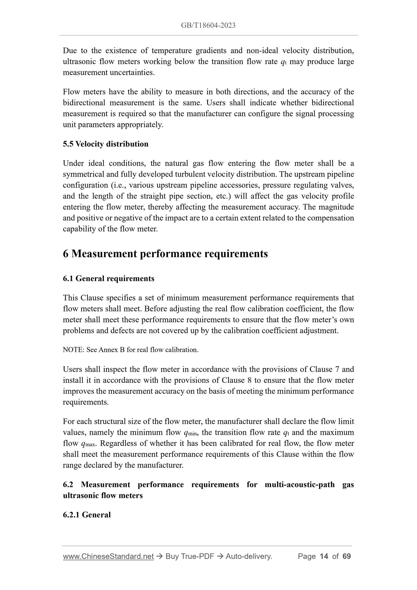
Due to the existence of temperature gradients and non-ideal velocity distribution,
ultrasonic flow meters working below the transition flow rate qt may produce large
measurement uncertainties.
Flow meters have the ability to measure in both directions, and the accuracy of the
bidirectional measurement is the same. Users shall indicate whether bidirectional
measurement is required so that the manufacturer can configure the signal processing
unit parameters appropriately.
5.5 Velocity distribution
Under ideal conditions, the natural gas flow entering the flow meter shall be a
symmetrical and fully developed turbulent velocity distribution. The upstream pipeline
configuration (i.e., various upstream pipeline accessories, pressure regulating valves,
and the length of the straight pipe section, etc.) will affect the gas velocity profile
entering the flow meter, thereby affecting the measurement accuracy. The magnitude
and positive or negative of the impact are to a certain extent related to the compensation
capability of the flow meter.
6 Measurement performance requirements
6.1 General requirements
This Clause specifies a set of minimum measurement performance requirements that
flow meters shall meet. Before adjusting the real flow calibration coefficient, the flow
meter shall meet these performance requirements to ensure that the flow meter’s own
problems and defects are not covered up by the calibration coefficient adjustment.
NOTE: See Annex B for real flow calibration.
Users shall inspect the flow meter in accordance with the provisions of Clause 7 and
install it in accordance with the provisions of Clause 8 to ensure that the flow meter
improves the measurement accuracy on the basis of meeting the minimum performance
requirements.
For each structural size of the flow meter, the manufacturer shall declare the flow limit
values, namely the minimum flow qmin, the transition flow rate qt and the maximum
flow qmax. Regardless of whether it has been calibrated for real flow, the flow meter
shall meet the measurement performance requirements of this Clause within the flow
range declared by the manufacturer.
6.2 Measurement performance requirements for multi-acoustic-path gas
ultrasonic flow meters
6.2.1 General
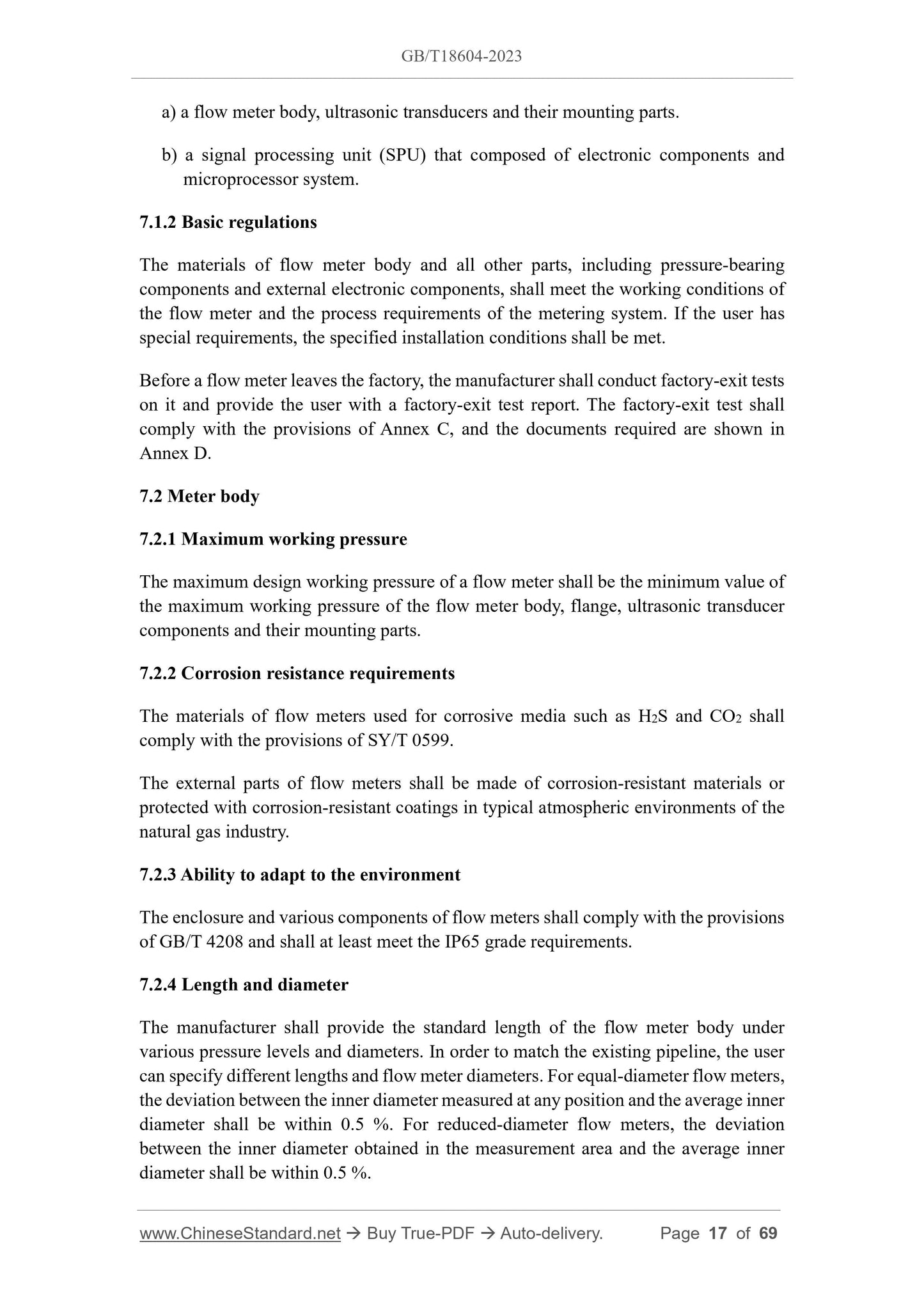
a) a flow meter body, ultrasonic transducers and their mounting parts.
b) a signal processing unit (SPU) that composed of electronic components and
microprocessor system.
7.1.2 Basic regulations
The materials of flow meter body and all other parts, including pressure-bearing
components and external electronic components, shall meet the working conditions of
the flow meter and the process requirements of the metering system. If the user has
special requirements, the specified installation conditions shall be met.
Before a flow meter leaves the factory, the manufacturer shall conduct factory-exit tests
on it and provide the user with a factory-exit test report. The factory-exit test shall
comply with the provisions of Annex C, and the documents required are shown in
Annex D.
7.2 Meter body
7.2.1 Maximum working pressure
The maximum design working pressure of a flow meter shall be the minimum value of
the maximum working pressure of the flow meter body, flange, ultrasonic transducer
components and their mounting parts.
7.2.2 Corrosion resistance requirements
The materials of flow meters used for corrosive media such as H2S and CO2 shall
comply with the provisions of SY/T 0599.
The external parts of flow meters shall be made of corrosion-resistant materials or
protected with corrosion-resistant coatings in typical atmospheric environments of the
natural gas industry.
7.2.3 Ability to adapt to the environment
The enclosure and various components of flow meters shall comply with the provisions
of GB/T 4208 and shall at least meet the IP65 grade requirements.
7.2.4 Length and diameter
The manufacturer shall provide the standard length of the flow meter body under
various pressure levels and diameters. In order to match the existing pipeline, the user
can specify different lengths and flow meter diameters. For equal-diameter flow meters,
the deviation between the inner diameter measured at any position and the average inner
diameter shall be within 0.5 %. For reduced-diameter flow meters, the deviation
between the inner diameter obtained in the measurement area and the average inner
diameter shall be within 0.5 %.
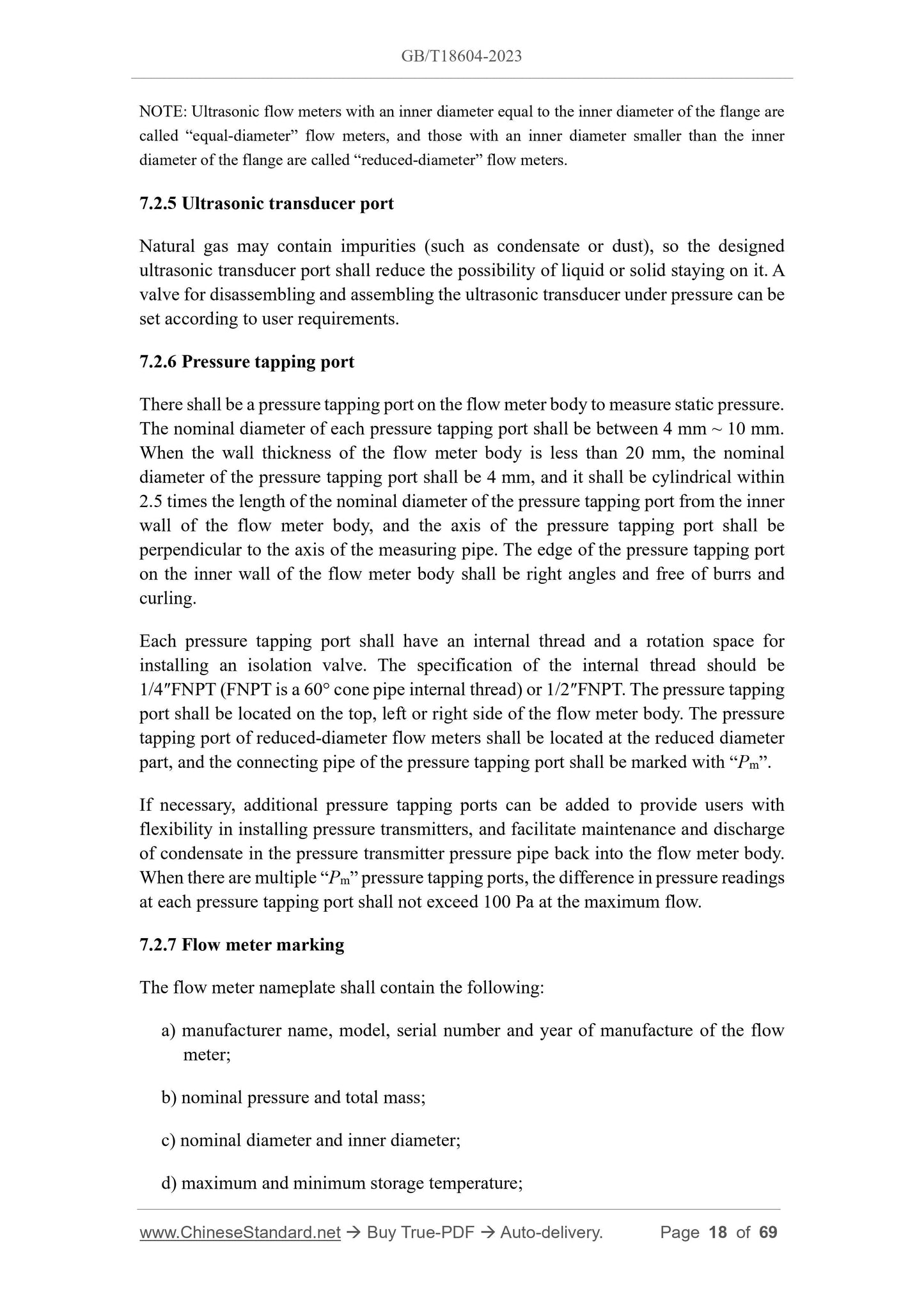
NOTE: Ultrasonic flow meters with an inner diameter equal to the inner diameter of the flange are
called “equal-diameter” flow meters, and those with an inner diameter smaller than the inner
diameter of the flange are called “reduced-diameter” flow meters.
7.2.5 Ultrasonic transducer port
Natural gas may contain impurities (such as condensate or dust), so the designed
ultrasonic transducer port shall reduce the possibility of liquid or solid staying on it. A
valve for disassembling and assembling the ultrasonic transducer under pressure can be
set according to user requirements.
7.2.6 Pressure tapping port
There shall be a pressure tapping port on the flow meter body to measure static pressure.
The nominal diameter of each pressure tapping port shall be between 4 mm ~ 10 mm.
When the wall thickness of the flow meter body is less than 20 mm, the nominal
diameter of the pressure tapping port shall be 4 mm, and it shall be cylindrical within
2.5 times the length of the nominal diameter of the pressure tapping port from the inner
wall of the flow meter body, and the axis of the pressure tapping port shall be
perpendicular to the axis of the measuring pipe. The edge of the pressure tapping port
on the inner wall of the flow meter body shall be right angles and free of burrs and
curling.
Each pressure tapping port shall have an internal thread and a rotation space for
installing an isolation valve. The specification of the internal thread should be
1/4″FNPT (FNPT is a 60° cone pipe internal thread) or 1/2″FNPT. The pressure tapping
port shall be located on the top, left or right side of the flow meter body. The pressure
tapping port of reduced-diameter flow meters shall be located at the reduced diameter
part, and the connecting pipe of the pressure tapping port shall be marked with “Pm”.
If necessary, additional pressure tapping ports can be added to provide users with
flexibility in installing pressure transmitters, and facilitate maintenance and discharge
of condensate in the pressure transmitter pressure pipe back into the flow meter body.
When there are multiple “Pm” pressure tapping ports, the difference in pressure readings
at each pressure tapping port shall not exceed 100 Pa at the maximum flow.
7.2.7 Flow meter marking
The flow meter nameplate shall contain the following:
a) manufacturer name, model, serial number and year of manufacture of the flow
meter;
b) nominal pressure and total mass;
c) nominal diameter and inner diameter;
d) maximum and minimum storage temperature;
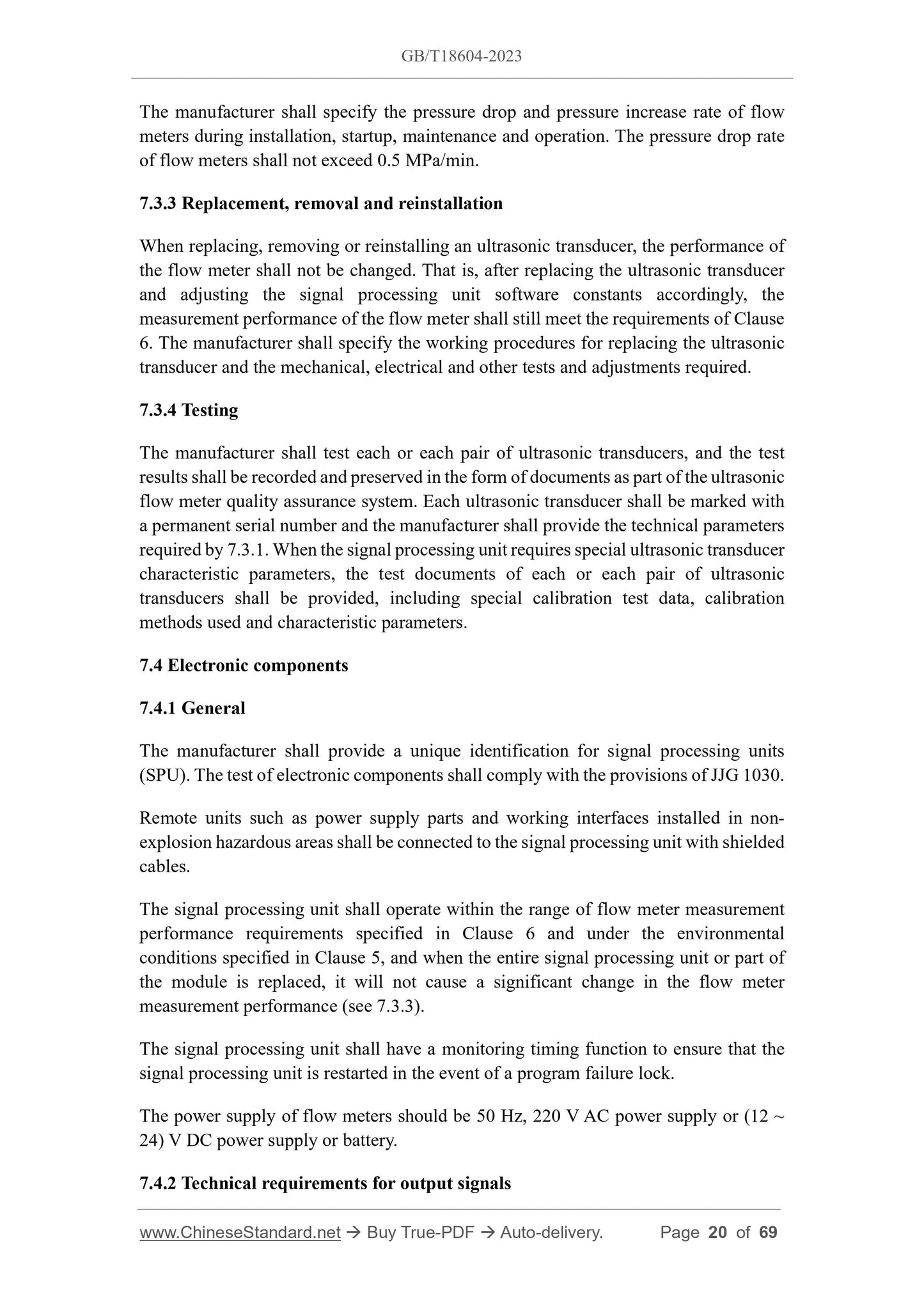
The manufacturer shall specify the pressure drop and pressure increase rate of flow
meters during installation, startup, maintenance and operation. The pressure drop rate
of flow meters shall not exceed 0.5 MPa/min.
7.3.3 Replacement, removal and reinstallation
When replacing, removing or reinstalling an ultrasonic transducer, the performance of
the flow meter shall not be changed. That is, after replacing the ultrasonic transducer
and adjusting the signal processing unit software constants accordingly, the
measurement performance of the flow meter shall still meet the requirements of Clause
6. The manufacturer shall specify the working procedures for replacing the ultrasonic
transducer and the mechanical, electrical and other tests and adjustments required.
7.3.4 Testing
The manufacturer shall test each or each pair of ultrasonic transducers, and the test
results shall be recorded and preserved in the form of documents as part of the ultrasonic
flow meter quality assurance system. Each ultrasonic transducer shall be marked with
a permanent serial number and the manufacturer shall provide the technical parameters
required by 7.3.1. When the signal processing unit requires special ultrasonic transducer
characteristic parameters, the test documents of each or each pair of ultrasonic
transducers shall be provided, including special calibration test data, calibration
methods used and characteristic parameters.
7.4 Electronic components
7.4.1 General
The manufacturer shall provide a unique identification for signal processing units
(SPU). The test of electronic components shall comply with the provisions of JJG 1030.
Remote units such as power supply parts and working interfaces installed in non-
explosion hazardous areas shall be connected to the signal processing unit with shielded
cables.
The signal processing unit shall operate within the range of flow meter measurement ...
View full details