1
/
of
12
PayPal, credit cards. Download editable-PDF and invoice in 1 second!
GB/T 18604-2014 English PDF (GB/T18604-2014)
Regular price
$285.00
Regular price
Sale price
$285.00
Unit price
/
per
Shipping calculated at checkout.
Couldn't load pickup availability
GB/T 18604-2014: Measurement of natural gas flow by gas ultrasonic flow meters
Delivery: 9 seconds. Download (and Email) true-PDF + Invoice.
Newer version: (Replacing this standard) GB/T 18604-2023
Get Quotation: Click GB/T 18604-2014 (Self-service in 1-minute)
Historical versions (Master-website): GB/T 18604-2023
Preview True-PDF (Reload/Scroll-down if blank)
GB/T 18604-2014
NATIONAL STANDARD OF THE
PEOPLE’S REPUBLIC OF CHINA
ICS 75.180.30
E 98
Replacing GB/T 18604-2001
Measurement of natural gas flow by gas ultrasonic
flow meters
ISSUED ON: FEBRUARY 19, 2014
IMPLEMENTED ON: JUNE 01, 2014
Issued by: General Administration of Quality Supervision, Inspection and
Quarantine;
Standardization Administration of the People's Republic of
China.
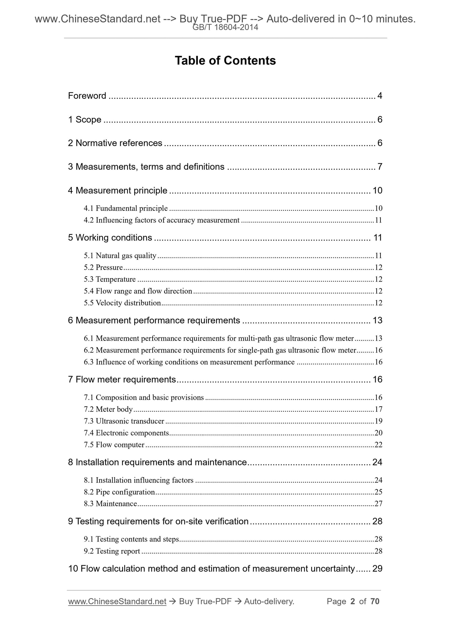
Table of Contents
Foreword ... 4
1 Scope ... 6
2 Normative references ... 6
3 Measurements, terms and definitions ... 7
4 Measurement principle ... 10
4.1 Fundamental principle ... 10
4.2 Influencing factors of accuracy measurement ... 11
5 Working conditions ... 11
5.1 Natural gas quality ... 11
5.2 Pressure ... 12
5.3 Temperature ... 12
5.4 Flow range and flow direction ... 12
5.5 Velocity distribution ... 12
6 Measurement performance requirements ... 13
6.1 Measurement performance requirements for multi-path gas ultrasonic flow meter ... 13
6.2 Measurement performance requirements for single-path gas ultrasonic flow meter ... 16
6.3 Influence of working conditions on measurement performance ... 16
7 Flow meter requirements ... 16
7.1 Composition and basic provisions ... 16
7.2 Meter body ... 17
7.3 Ultrasonic transducer ... 19
7.4 Electronic components ... 20
7.5 Flow computer ... 22
8 Installation requirements and maintenance ... 24
8.1 Installation influencing factors ... 24
8.2 Pipe configuration ... 25
8.3 Maintenance ... 27
9 Testing requirements for on-site verification ... 28
9.1 Testing contents and steps ... 28
9.2 Testing report ... 28
10 Flow calculation method and estimation of measurement uncertainty ... 29
10.1 Flow calculation under standard reference conditions ... 29
10.2 Determination of measured flow value under standard reference conditions... 31
10.3 Flow calculation under working conditions ... 31
10.4 Estimation of flow measurement uncertainty ... 31
Annex A (informative) Fundamental principles ... 35
Annex B (normative) Flow calibration of flow meter components ... 46
Annex C (normative) Exit-factory testing requirements ... 53
Annex D (informative) Documents available ... 56
Annex E (informative) Generation and prevention measures of acoustic noise
... 59
Annex F (informative) Performance verification tests of flow meter and flow
conditioner ... 65
Annex G (informative) Monitoring and guarantee of on-site measurement
performance of flow meter ... 67
Foreword
This Standard was drafted in accordance with the rules given in GB/T 1.1-2009.
This Standard replaces GB/T 18604-2001 “Measurement of natural gas flow by
ultrasonic flow meter”. Compared with GB/T 18604-2001, in addition to editorial
modifications, main technical changes as follows:
- added three terms: maximum error shift with one path failed, speed of
sound (SOS) deviation and metering package (see 3.2.17, 3.2.18 and
3.2.19);
- modified influencing factors of measurement accuracy; divided the
influencing factors into two categories: internal factors and external factors
(see Clause 4);
- further specified the range of working temperature as medium temperature
and ambient temperature (see 5.3);
- improved the requirements for zero-flow reading of multi-path gas ultrasonic
flow meter; added two technical requirements of sound velocity deviation
and maximum sound velocity difference; modified the maximum peak-to-
peak error requirement above the demarcation flow (see 6.1);
- added that according to the ambient conditions and working conditions,
taking necessary thermal insulation, anti-freeze measures, and related
requirements for acoustic noise and pulsation to flow meter components
(including upstream and downstream straight pipe sections, flow meters
and flow conditioners, temperature tapping holes and sampling holes)
(see 8.1.1, 8.1.4, 8.1.5 and Annex E);
- modified relevant requirements for pipe installation upstream straight pipe
section and flow conditioner installation position, temperature
measurement hole and sampling hole insertion depth, flow conditioner
(see 8.2.2, 8.2.5 and 8.2.7 and Annex F);
- added the requirements for on-site measurement performance of ultrasonic
flow meters in routine maintenance (see 8.3.1 and Annex G);
- added the requirements that theoretical sound velocity is calculated
according to the method provided by AGA Report No.10 “Speed of sound
in natural gas and other related hydrocarbon gases” and other methods
that are same as the calculation (see 9.1.3);
- added the calculation method and uncertainty estimation for mass flow and
energy flow (see Clause 10);
- modified flow calibration to flow calibration of metering package; modified
stability requirements for temperature and pressure, test traffic point (see
B.2.2 and B.3.3);
- deleted the original Annex E “Upper and lower pipe length requirements”;
- added technical requirements of “acoustic noise generation and prevention
measures” (see Annex E);
- added technical requirements of “flow meter and flow conditioner
performance verification test” (see Annex F);
- added technical requirements of “monitoring and guarantee of flow meter
on-site measurement performance” (see Annex G).
This Standard uses redrafting method to modify and adopt AGA Report No.10
“Speed of sound in natural gas and other related hydrocarbon gases”.
This Standard was proposed by and shall be under the jurisdiction of National
Technical Committee on Petroleum Gas of Standardization Administration of
China (SAC/TC 355).
The drafting organizations of this Standard: National Oil and Gas Large Flow
Metering Station Chengdu Sub-Station, PetroChina Southwest Oil and Gas
Field Branch, PetroChina Group Engineering Design Co., Ltd. Southwest
Branch.
Main drafters of this Standard: Duan Jiqin, He Min, Wen Dailong, Ren Gui,
Huang He, Liu Yongming, Chen Huiyu, Wang Qiang, Chen Qi, Ni Rui.
Measurement of natural gas flow by gas ultrasonic
flow meters
1 Scope
This Standard specifies measurement performance requirements of gas
ultrasonic flow meters, meter body requirements, installation and maintenance,
field verification test requirements, and flow calculation methods and
measurement uncertainty estimates.
This Standard is applicable to gas ultrasonic flow meters of plug-in transit-time
difference method (hereinafter referred to as the flow meter), which are
generally used for natural gas flow measurement in gathering devices, gas
pipelines, storage facilities, gas distribution systems and customer metering
systems. The use of external clamp-on gas ultrasonic flow meter can refer to
this Standard.
2 Normative references
The following referenced documents are indispensable for the application of
this document. For dated references, only the edition cited applies. For undated
references, the latest edition of the referenced document (including any
amendments) applies.
GB 3836.1, Explosive atmospheres - Part 1: Equipment - General
requirements
GB 3836.2, Explosive atmospheres - Part 2: Equipment protection by
flameproof enclosures “d”
GB 3836.4, Explosive atmospheres - Part 4: Equipment protection by
intrinsic safety “i”
GB/T 4208, Degrees of protection provided by enclosure (IP code) (IEC
60529)
GB/T 11062-1998, Natural gas - Calculation of calorific values, density,
relative density and Wobbe index from composition
GB/T 13610, Analysis of natural gas by gas chromatography
GB/T 17747 (all parts), Natural gas - Calculation of compression factor
GB/T 21446-2008, Measurement of natural gas flow by means of standard
orifice meter
SY/T 0599-2006, Metallic material requirements - Resistance to sulfide
stress cracking and stress corrosion cracking for gas surface equipment
JJG 1030-2007, Verification Regulation of Ultrasonic Flowmeters
ISO 5167-1:2003, Measurement of fluid flow by means of pressure
differential devices inserted in circular cross-section conduits running full -
Part 1: General principles and requirements
AGA Report No.10, Speed of sound in natural gas and other related
hydrocarbon gases
3 Measurements, terms and definitions
3.1 Measurements
See Table 1 for the measurements, names and symbols of unit used in this
Standard.
Table 1 -- Measurements and names as well as symbols of unit
Symbol of
measurement Name of measurement
Measurement
dimension Symbol of unit
D Inner diameter of flow meter L m
kc Velocity distribution correction 1
L Path length L m
P Static pressure ML-1T-2 Pa
qv Volumetric flowrate L3T-1 m3/s
qm Mass flowrate MT-1 Kg/s
qe Energy flowrate L3T-1 J/s
qt Transition flowrate L3T-1 m3/h
Qn
Volume accumulation over a period
of time under standard reference
conditions
L3 M3
T Airflow thermodynamic temperature K
t Time T s
V Mean axial fluid velocity LT-1 m/s
Average flow velocity along acoustic
path LT
-1 m/s
X Axial distance L m
Z Compression factor 1
φ Path angle 1 rad
NOTE 1: In the measurement dimension, symbol L refers to length, symbol T refers to time, symbol
M refers to mass and symbol refers to thermodynamic temperature.
NOTE 2: The symbols not listed in the table are explained in the text.
3.2 Terms and definitions
The following terms and definitions apply to this document.
3.2.1 transit-time difference method
A gas flow measurement method that within the same stroke in the flowing gas,
using the transit-time difference of two ultrasonic signals of downstream and
upstream transits to determine the average flow velocity along acoustic path.
3.2.2 ultrasonic transducer
A component that converts acoustic energy to electrical signal and vice versa.
Generally, it is installed in a pair and the pair work simultaneously.
3.2.3 signal processing unit
A part of flow meter, consisting of electronic components and microprocessor
system.
3.2.4 meter body
A pipe section where the gas to be tested passes, where components such as
ultrasonic transducer and pressure measuring connector are installed, that is
manufactured in a special way to comply with relevant regulations in any aspect.
3.2.5 acoustic path
The actual path of the ultrasound signal between a pair of transmitting and
receiving ultrasound transducers.
3.2.6 path length; L
The distance between the end faces of a pair of ultrasonic transducers (see
Figure 1).
3.2.7 axial distance; X
The projection length of path length on the parallel line of pipe axis (see Figure
1).
Figure 1 -- Simplified geometric relationship diagram of plug-in gas
ultrasonic flow measurement
3.2.8 path angle; φ
The angle between acoustic path and pipe axis (see Figure 1).
3.2.9 average flow velocity along acoustic path;
Gas flow velocity in a plane that is determined by acoustic path and flow
direction.
3.2.10 mean axial fluid velocity; V
Ratio of flowrate to measured cross-sectional area.
3.2.11 velocity distribution correction; kc
Ratio of mean axial fluid velocity to average flow velocity along acoustic path.
3.2.12 velocity sampling interval
Time interval between two adjacent gas flow measurements by a pair of
ultrasonic transducers or acoustic paths.
3.2.13 zero-flow reading
The reading of the maximum permissible flow rate when gas is in a state of rest.
3.2.14 transition flow rate; qt
The flow value between the maximum flow and the minimum flow. It divides the
flow range into two zones with different tolerances, that is, “high zone” and “low
zone” (see Figure 2).
3.2.15 maximum peak-to-peak error
The difference between the upper limit maximum error point and the lower limit
maximum error point (see Figure 2).
3.2.16 flow calibration factor
Flow meter coefficient that to conduct flow calibration on the flow meter and
correct the test results according to a certain correction method, hereinafter
referred to as the calibration factor.
3.2.17 maximum error shift with one path failed
At the same flow, the maximum difference BETWEEN the measurement error
when all acoustic paths work AND the measurement error when one acoustic
path fails.
3.2.18 speed of sound (SOS) deviation
The maximum relative deviation between average sound velocity obtained by
the measurement of flow meter and theoretical sound velocity in the gas.
3.2.19 metering package
The component that consists of a flow meter, supporting upstream and
downstream straight pipe sections, temperature measuring hole, pressure
obtaining hole as well as flow conditioner.
4 Measurement principle
4.1 Fundamental principle
The gas ultrasonic flow meter of transit-time difference method is a velocity flow
meter that measures high frequency sound pulse transit-time to obtain gas flow.
The transit time is measured by the acoustic pulses that are transmitted and
received between pairs of transducers outside the pipe or within the pipe. The
acoustic pulse transits along the diagonal direction (see Figure 1). Acoustic
pulses transmitted downstream are accelerated by airflow while acoustic pulses
transmitted in reverse flow shall be decelerated. The transit-time difference is
related to the mean axial fluid velocity. Use numerical calculation technique to
calculate the mean axial fluid velocity and the flow that pass through the gas
ultrasonic flow meter under working conditions. The flow meter that only has
one acoustic path is called single-path gas ultrasonic flow meter. The flow meter
that has two or more acoustic paths is called multi-path gas ultrasonic flow
meter. When the ultrasonic transducer is in direct contact with the gas, it is
called plug-in. When the ultrasonic transducer is not in direct contact with the
gas, it is called external clamp-on.
See Annex A for more details.
4.2 Influencing factors of accuracy measurement
4.2.1 Internal factors include:
a) Geometric size of meter body as well as accuracy and stability of
ultra...
Share