Skip to product information
1 of 8

PayPal, credit cards. Download editable-PDF and invoice in 1 second!

GB/T 18443.3-2010 English PDF (GBT18443.3-2010)

GB/T 18443.3-2010 English PDF (GBT18443.3-2010)

Regular price $85.00 USD
Regular price Sale price $85.00 USD
Sale Sold out
Shipping calculated at checkout.
Quotation: In 1-minute, 24-hr self-service. Click here GB/T 18443.3-2010 to get it for Purchase Approval, Bank TT...

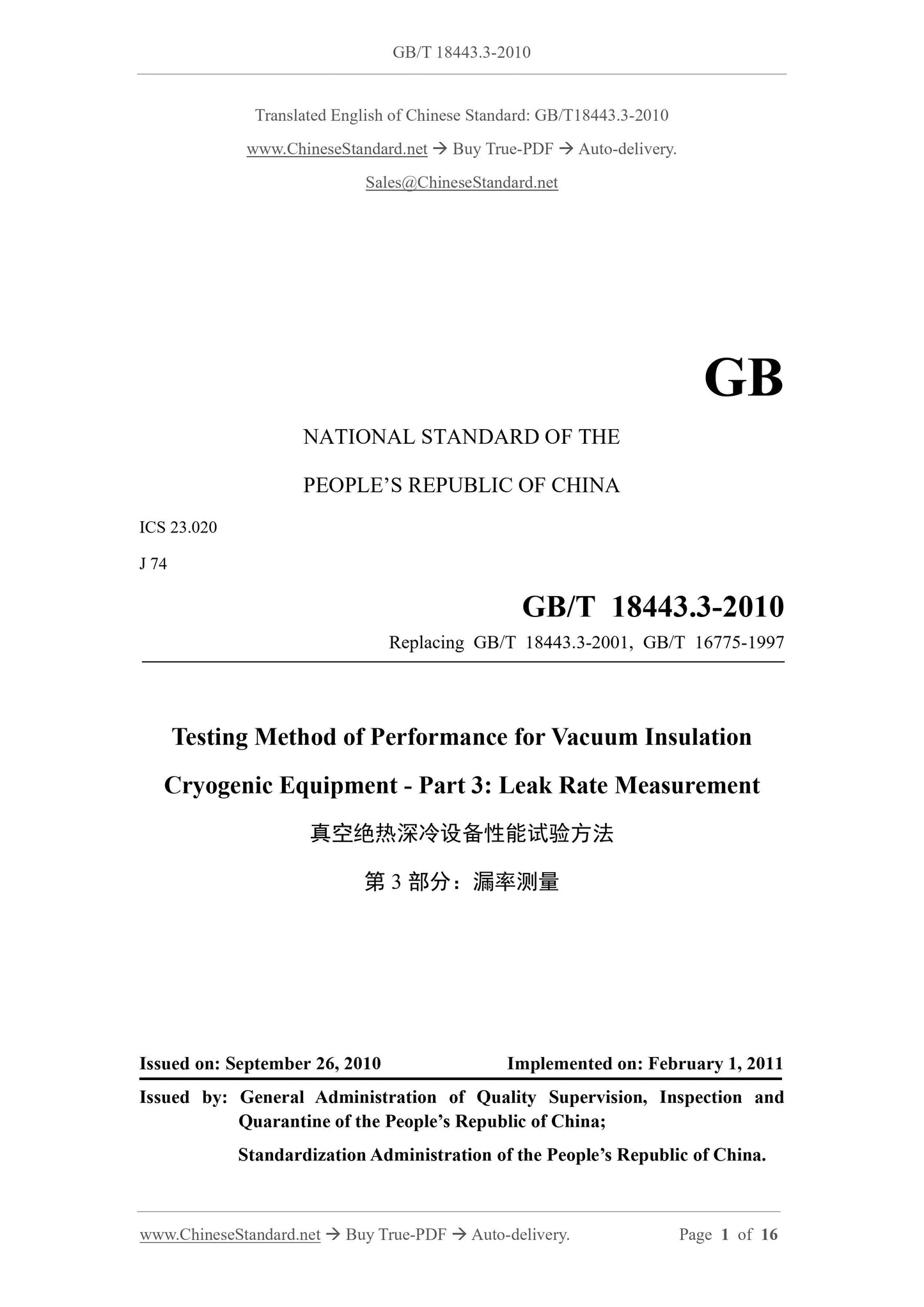
GB/T 18443.3-2010: Testing method of performance for vacuum insulation cryogenic equipment -- Part 3: Leak rate measurement

This Part of GB/T 18443 specifies the test principles and methods, test devices, equipment and instruments, test conditions and preparation, test procedures, data processing, test records and test reports of the leak rate measurement of vacuum insulated cryogenic equipment. This Part is applicable to the leak rate measurement of vacuum insulated cryogenic equipment, such as: vacuum insulated cryogenic pressure vessels, vacuum insulated cryogenic welding gas cylinders and vacuum insulated pipes and their pipe fittings, except for liquid hydrogen storage and transportation media. The other equipment may take this as a reference.
GB/T 18443.3-2010
NATIONAL STANDARD OF THE
PEOPLE’S REPUBLIC OF CHINA
ICS 23.020
J 74
Replacing GB/T 18443.3-2001, GB/T 16775-1997
Testing Method of Performance for Vacuum Insulation
Cryogenic Equipment - Part 3.Leak Rate Measurement
ISSUED ON. SEPTEMBER 26, 2010
IMPLEMENTED ON. FEBRUARY 1, 2011
Issued by. General Administration of Quality Supervision, Inspection and Quarantine of the People’s Republic of China;
Standardization Administration of the People’s Republic of China.
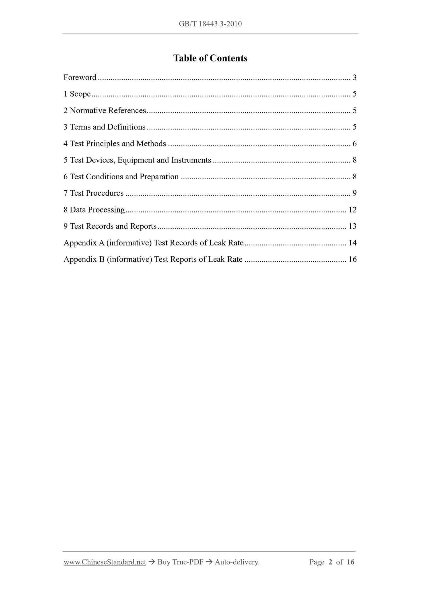
Table of Contents
Foreword... 3
1 Scope... 5
2 Normative References... 5
3 Terms and Definitions... 5
4 Test Principles and Methods... 6
5 Test Devices, Equipment and Instruments... 8
6 Test Conditions and Preparation... 8
7 Test Procedures... 9
8 Data Processing... 12
9 Test Records and Reports... 13
Appendix A (informative) Test Records of Leak Rate... 14
Appendix B (informative) Test Reports of Leak Rate... 16
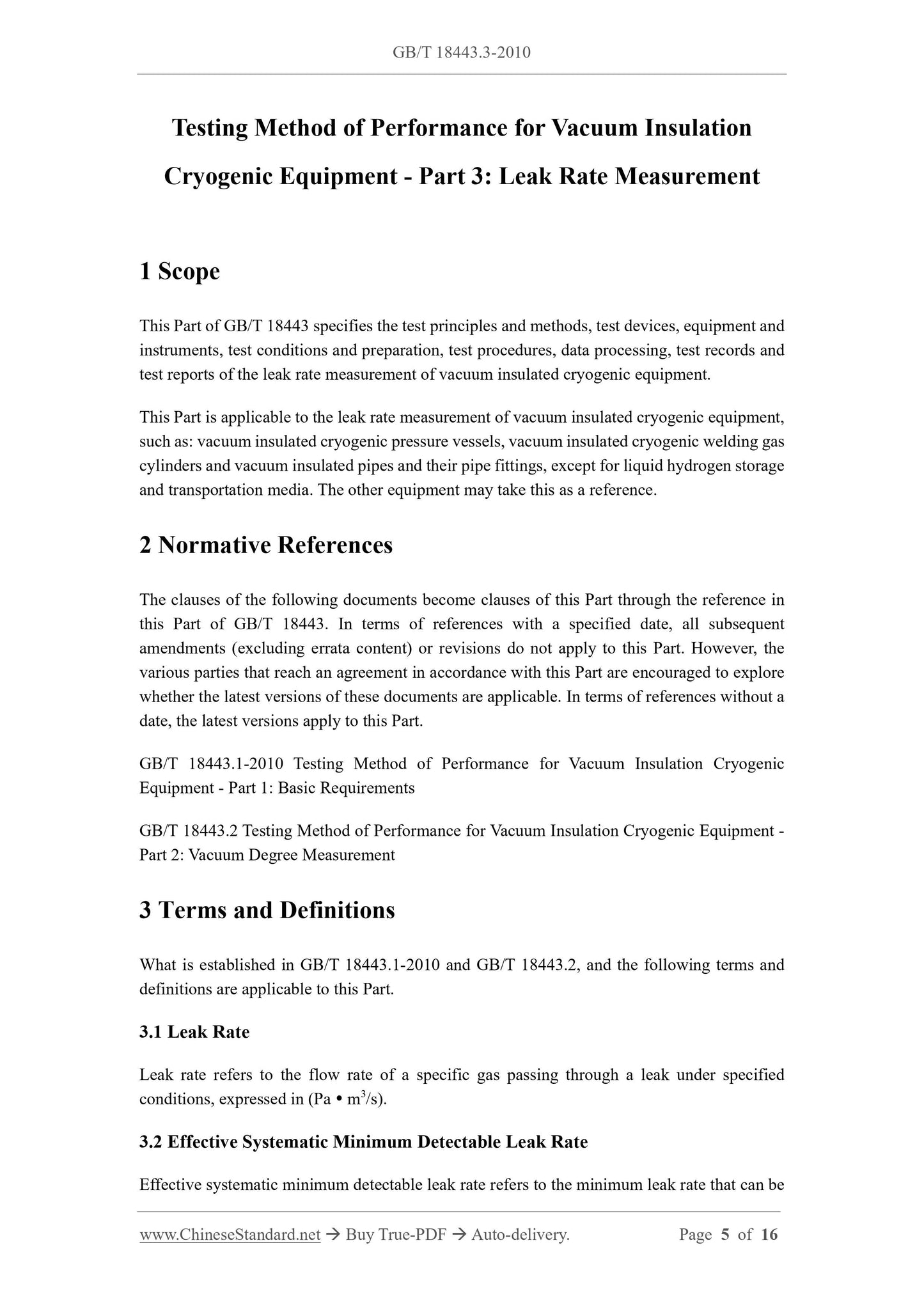
Testing Method of Performance for Vacuum Insulation
Cryogenic Equipment - Part 3.Leak Rate Measurement
1 Scope
This Part of GB/T 18443 specifies the test principles and methods, test devices, equipment and instruments, test conditions and preparation, test procedures, data processing, test records and test reports of the leak rate measurement of vacuum insulated cryogenic equipment. This Part is applicable to the leak rate measurement of vacuum insulated cryogenic equipment, such as. vacuum insulated cryogenic pressure vessels, vacuum insulated cryogenic welding gas cylinders and vacuum insulated pipes and their pipe fittings, except for liquid hydrogen storage and transportation media. The other equipment may take this as a reference. 2 Normative References
The clauses of the following documents become clauses of this Part through the reference in this Part of GB/T 18443.In terms of references with a specified date, all subsequent amendments (excluding errata content) or revisions do not apply to this Part. However, the various parties that reach an agreement in accordance with this Part are encouraged to explore whether the latest versions of these documents are applicable. In terms of references without a date, the latest versions apply to this Part.
GB/T 18443.1-2010 Testing Method of Performance for Vacuum Insulation Cryogenic Equipment - Part 1.Basic Requirements
GB/T 18443.2 Testing Method of Performance for Vacuum Insulation Cryogenic Equipment - Part 2.Vacuum Degree Measurement
3 Terms and Definitions
What is established in GB/T 18443.1-2010 and GB/T 18443.2, and the following terms and definitions are applicable to this Part.
3.1 Leak Rate
Leak rate refers to the flow rate of a specific gas passing through a leak under specified conditions, expressed in (Pa  m3/s).
3.2 Effective Systematic Minimum Detectable Leak Rate
Effective systematic minimum detectable leak rate refers to the minimum leak rate that can be detected by the instrument for the measured piece under specific working conditions, methods and systems of leak detection, expressed in (Pa  m3/s).
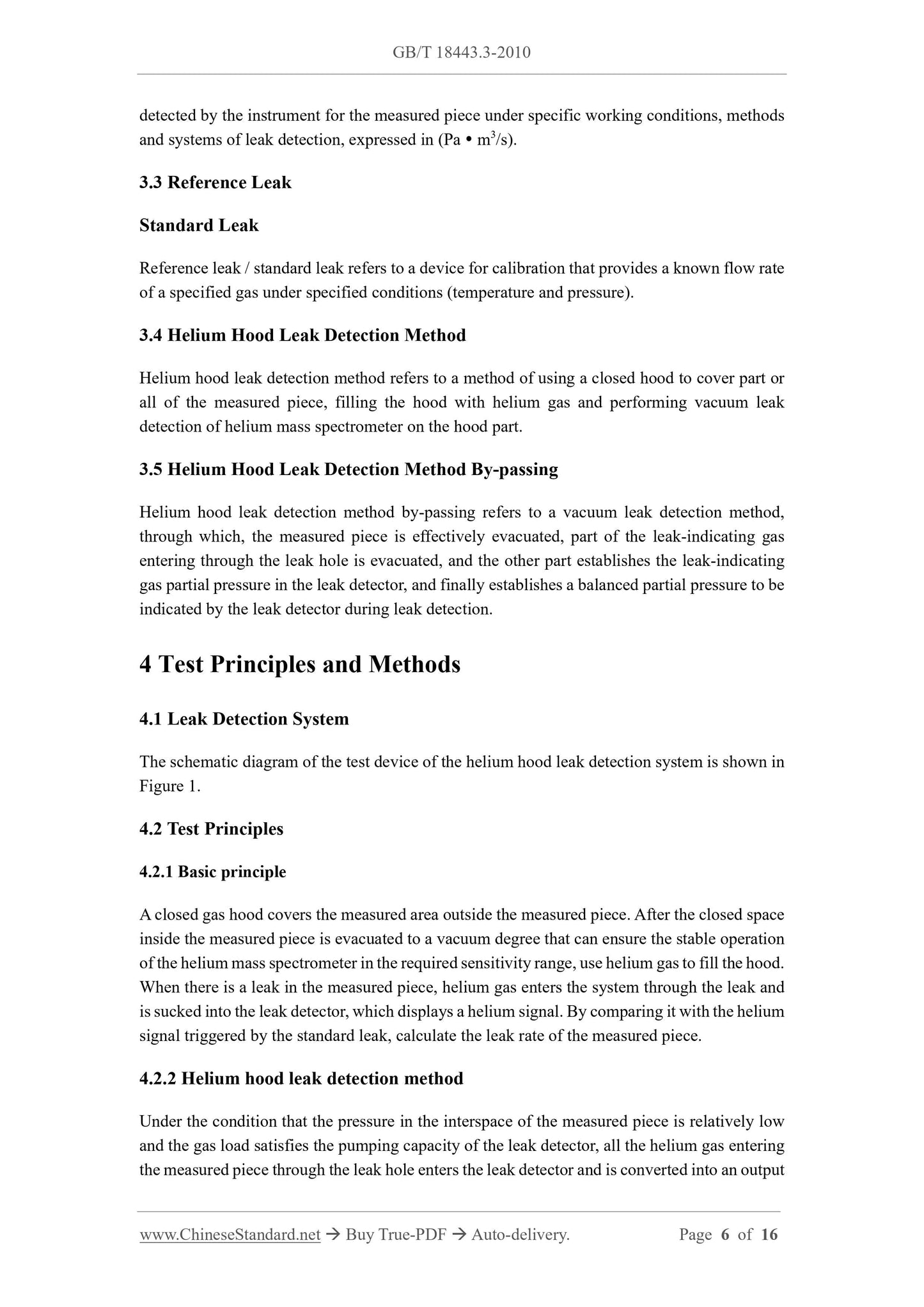
3.3 Reference Leak
Standard Leak
Reference leak / standard leak refers to a device for calibration that provides a known flow rate of a specified gas under specified conditions (temperature and pressure). 3.4 Helium Hood Leak Detection Method
Helium hood leak detection method refers to a method of using a closed hood to cover part or all of the measured piece, filling the hood with helium gas and performing vacuum leak detection of helium mass spectrometer on the hood part.
3.5 Helium Hood Leak Detection Method By-passing
Helium hood leak detection method by-passing refers to a vacuum leak detection method, through which, the measured piece is effectively evacuated, part of the leak-indicating gas entering through the leak hole is evacuated, and the other part establishes the leak-indicating gas partial pressure in the leak detector, and finally establishes a balanced partial pressure to be indicated by the leak detector during leak detection.
4 Test Principles and Methods
4.1 Leak Detection System
The schematic diagram of the test device of the helium hood leak detection system is shown in Figure 1.
4.2 Test Principles
4.2.1 Basic principle
A closed gas hood covers the measured area outside the measured piece. After the closed space inside the measured piece is evacuated to a vacuum degree that can ensure the stable operation of the helium mass spectrometer in the required sensitivity range, use helium gas to fill the hood. When there is a leak in the measured piece, helium gas enters the system through the leak and is sucked into the leak detector, which displays a helium signal. By comparing it with the helium signal triggered by the standard leak, calculate the leak rate of the measured piece. 4.2.2 Helium hood leak detection method
Under the condition that the pressure in the interspace of the measured piece is relatively low and the gas load satisfies the pumping capacity of the leak detector, all the helium gas entering the measured piece through the leak hole enters the leak detector and is converted into an output 5 Test Devices, Equipment and Instruments
The test devices, equipment and instruments shall comply with the stipulations of 4.2 in GB/T 18443.1, and satisfy the following requirements.
a) The leak detector shall adopt a helium mass spectrometer leak detector, whose minimum detectable leak rate shall be one order of magnitude lower than the specified leak rate index of the measured piece;
b) In accordance with the leak rate index of the measured piece, select the standard leak with the same order of magnitude of thin-film helium-permeable or channel-type leaks.
6 Test Conditions and Preparation
6.1 The basic test requirements shall comply with the stipulations of GB/T 18443.1 and satisfy the following requirements.
a) Before leak detection, the helium mass spectrometer leak detector shall adjust various working parameters of the instrument in accordance with the instruction manual, so that the instrument is in the optimal working state. Calibrate and debug its effective minimum detectable leak rate Qmin, which shall be less than the specified leak rate index of the measured piece by an order of magnitude.
b) When the helium hood method is adopted for leak detection, a suitable helium hood shall be made in accordance with the size of the measured piece. The helium hood should select a plastic thin film with better air tightness.
c) The purity of helium gas used for the detection shall not be lower than 90%. d) When the vacuum insulated cryogenic equipment stores flammable and explosive cryogenic liquids, before assembly, a helium mass spectrometer leak detector shall be used to determine the total leak rate.
6.2 Selection of Test Methods
6.2.1 When the gas load of the measured piece satisfies the pumping capacity of the leak detector, the helium hood leak detection method shall be selected for the measurement. 6.2.2 When the gas load of the measured piece cannot satisfy the pumping capacity of the leak detector, and an auxiliary pump needs to be added for pumping, the helium hood leak detection method by-passing shall be selected for the measurement.
7 Test Procedures
7.1 Helium Hood Leak Detection Method
7.1.1 The measurement of the effective minimum detectable leak rate of the instrument shall comply with the following requirements.
a) Turn on the leak detector and close the leak detection valve; maintain the leak detector under the optimal working condition;
b) Close the standard leak of the leak detector; measure the background noise Nn within 2 min;
c) Read the instrument background N0;
d) Open the standard leak of the leak detector; read and record the stable output value Nsp indicated by the leak detector.
7.1.2 The connection of the measured piece shall comply with the following requirements. a) In accordance with Figure 1, connect the measured piece. In addition, in accordance with the volume of the measured piece, select and configure a suitable leak detection system. The standard leak shall be installed at one end of the vacuum valve of the measured piece;
b) Under the condition of closing the vacuum valve, and opening the detection valve, diverter valve and leak detection valve of the measured piece, start the vacuum unit; c) In accordance with the instruction manual, carry out self-calibration of the instrument; the leak detector shall comply with the requirements of Chapter 5;
d) When the pressure indicated by the vacuum gauge is less than the pressure of the measured piece, close the diverter valve.
7.1.3 The measurement of the effective systematic minimum detectable leak rate shall comply with the following requirements.
a) Open the detection valve. After the pressure indicated by the vacuum gauge is less than the vacuum interspace pressure of the measured piece, open the vacuum valve of the measured piece; the leak detector maintains a stable working pressure; b) Close the standard leak valve; measure the background noise In within 2 min; c) Read the system background I0;
d) Open the standard leak valve; read and record the stable output value Isp indicated by the leak detector.
b) When the vacuum valve of the measured piece and the leak detection valve are not opened, start the vacuum unit and the leak detector, open the detection valve and the diverter valve. After the pumping pipeline reaches a stable vacuum, open the leak detection valve and the vacuum valve of the measured piece;
c) Slowly adjust the diverter valve; maintain the leak detector at a stable working pressure.
7.2.3 The measurement of the effective systematic minimum detectable leak rate shall comply with the following requirements.
a) Open the detection valve. After the pressure indicated by the vacuum gauge is lower than the pressure of the vacuum interspace of the measured piece, open the vacuum valve of the measured piece; the state of the diverter valve shall comply with the stipulations of 7.2.2 c);
b) In accordance with the requirements of 7.1.3, perform the measurement. 7.2.4 The leak detection of the measured piece shall comply with the following requirements. a) Open the vacuum valve and detection valve of the measured piece; the state of the leak detection valve shall comply with the stipulations of 7.2.2; the diverter valve shall remain unchanged. Record the background indication value I0;
b) Put the helium hood on the vacuum insulated cryogenic equipment and seal it; c) Use helium gas with a known concentration to fill the helium hood and inner container. Generally speaking, the helium concentration after inflation shall not be lower than 10%;
d) Estimate the helium concentration in the helium hood and record the helium concentration ;
e) Within the specified observation time, read and record the output value Iv indicated by the leak detector. The observation time is generally not less than 10 min; f) After the measurement is completed, close the vacuum valve of the measured piece. 7.2.5 The re-detection of the effective systematic minimum detectable leak rate shall comply with the following requirements.
a) In accordance with 7.1.5, re-detect the effective systematic minimum detectable leak rate;
b) In accordance with 7.1.5, determine whether the leak detection can be terminated. 8 Data Processing
8.1 The effective minimum detectable leak rate of the instrument shall be calculated in accordance with Formula (1).
Where,
Qmin---the effective minimum detectable leak rate of the instrument, expressed in (Pa  m3/s); Nn---the background noise of the instrument, expressed in (V) or (Pa  m3/s); Nsp---after opening the standard leak valve, the stable output value indicated by the leak detector, expressed in (V) or (Pa  m3/s);
N0---the instrument background, expressed in (V) or (Pa  m3/s);
Qsp---the leak rate of the standard leak, expressed in (Pa  m3/s).
8.2 The effective systematic minimum detectable leak rate shall be calculated in accordance with Formula (2).
Where,
Q0---the effective systematic minimum detectable leak rate, expressed in (Pa  m3/s); In---the background noise of the system, expressed in (V) or (Pa  m3/s); Isp---after opening the standard leak valve, the stable output value indicated by the leak detector, expressed in (V) or (Pa  m3/s);
I0---the system background, expressed in (V) or (Pa  m3/s);
Qsp---the leak rate of the standard leak, expressed in (Pa  m3/s).
8.3 The leak rate of the measured piece shall be calculated in accordance with Formula (3). Where,

View full details