Skip to product information
1 of 10

PayPal, credit cards. Download editable-PDF and invoice in 1 second!

GB/T 18362-2008 English PDF (GB/T18362-2008)

GB/T 18362-2008 English PDF (GB/T18362-2008)

Regular price $150.00
Regular price Sale price $150.00
Sale Sold out
Shipping calculated at checkout.
GB/T 18362-2008: Direct-fired lithium bromide absorption water chiller (heater)
Delivery: 9 seconds. Download (& Email) true-PDF + Invoice.
Get Quotation: Click GB/T 18362-2008 (Self-service in 1-minute)
Historical versions (Master-website): GB/T 18362-2008
Preview True-PDF (Reload/Scroll-down if blank)

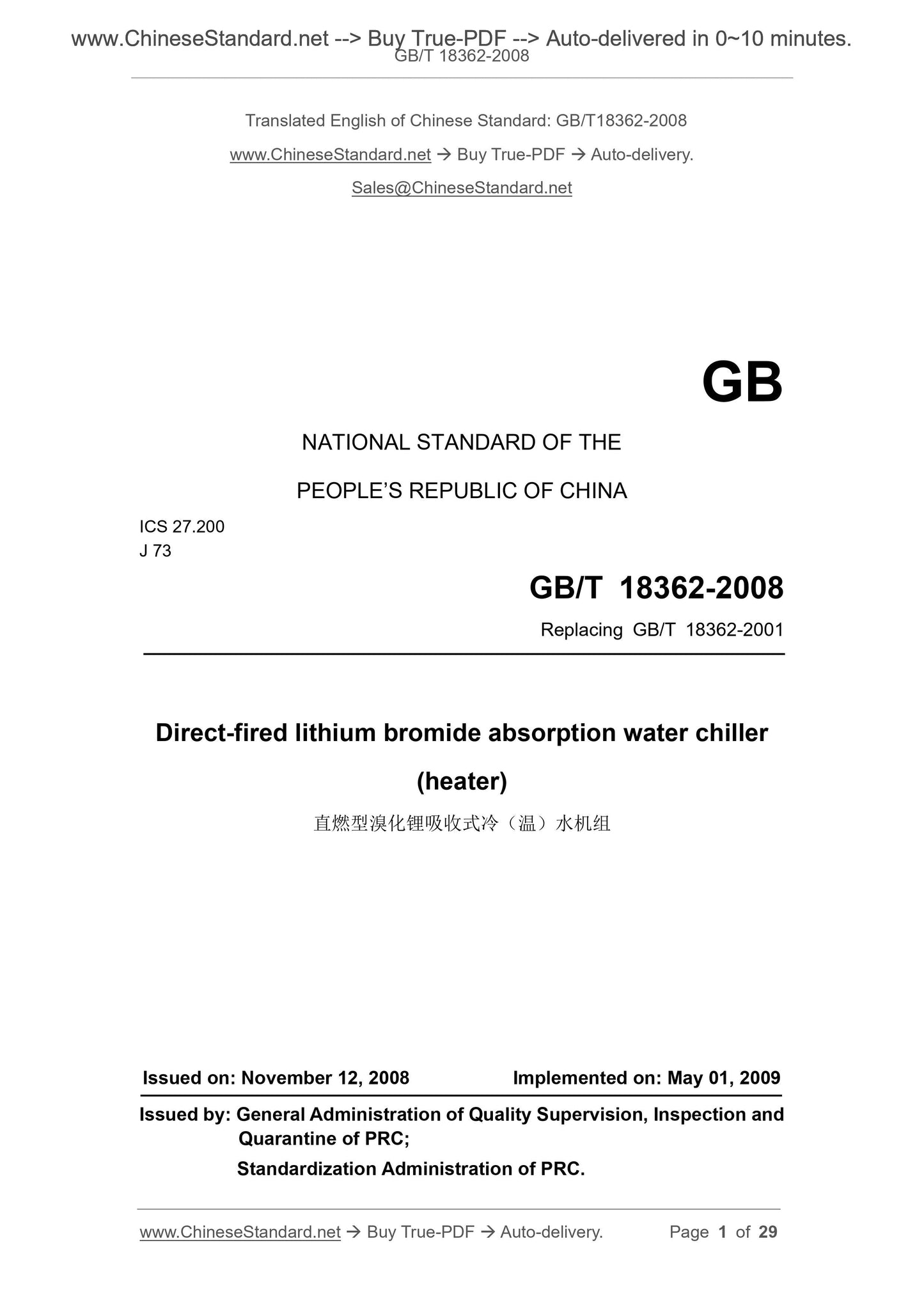
GB/T 18362-2008
GB
NATIONAL STANDARD OF THE
PEOPLE’S REPUBLIC OF CHINA
ICS 27.200
J 73
Replacing GB/T 18362-2001
Direct-fired lithium bromide absorption water chiller
(heater)
ISSUED ON: NOVEMBER 12, 2008
IMPLEMENTED ON: MAY 01, 2009
Issued by: General Administration of Quality Supervision, Inspection and
Quarantine of PRC;
Standardization Administration of PRC.
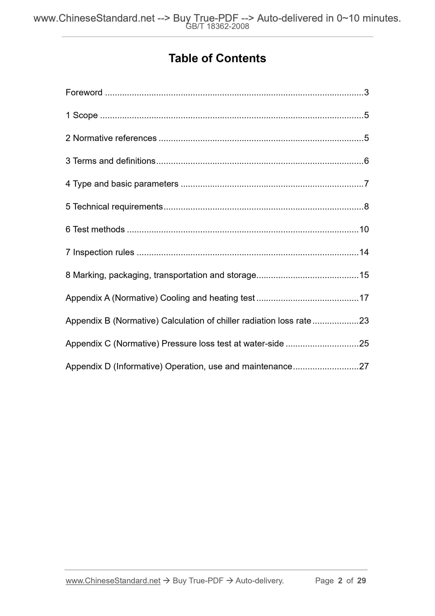
Table of Contents
Foreword ... 3 
1 Scope ... 5 
2 Normative references ... 5 
3 Terms and definitions ... 6 
4 Type and basic parameters ... 7 
5 Technical requirements ... 8 
6 Test methods ... 10 
7 Inspection rules ... 14 
8 Marking, packaging, transportation and storage ... 15 
Appendix A (Normative) Cooling and heating test ... 17 
Appendix B (Normative) Calculation of chiller radiation loss rate ... 23 
Appendix C (Normative) Pressure loss test at water-side ... 25 
Appendix D (Informative) Operation, use and maintenance ... 27 
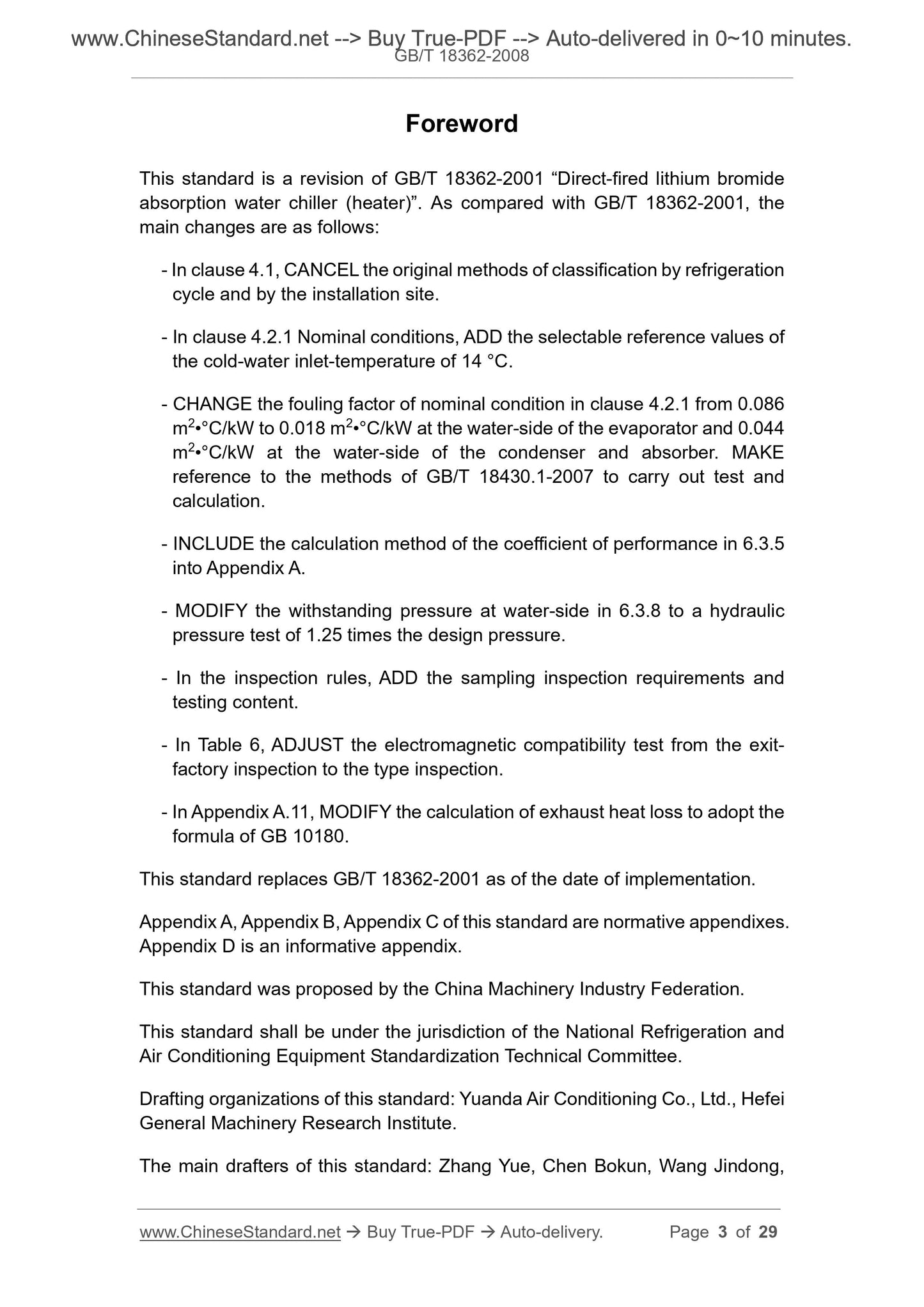
Foreword
This standard is a revision of GB/T 18362-2001 “Direct-fired lithium bromide
absorption water chiller (heater)”. As compared with GB/T 18362-2001, the
main changes are as follows:
- In clause 4.1, CANCEL the original methods of classification by refrigeration
cycle and by the installation site.
- In clause 4.2.1 Nominal conditions, ADD the selectable reference values of
the cold-water inlet-temperature of 14 °C.
- CHANGE the fouling factor of nominal condition in clause 4.2.1 from 0.086
m2•°C/kW to 0.018 m2•°C/kW at the water-side of the evaporator and 0.044
m2•°C/kW at the water-side of the condenser and absorber. MAKE
reference to the methods of GB/T 18430.1-2007 to carry out test and
calculation.
- INCLUDE the calculation method of the coefficient of performance in 6.3.5
into Appendix A.
- MODIFY the withstanding pressure at water-side in 6.3.8 to a hydraulic
pressure test of 1.25 times the design pressure.
- In the inspection rules, ADD the sampling inspection requirements and
testing content.
- In Table 6, ADJUST the electromagnetic compatibility test from the exit-
factory inspection to the type inspection.
- In Appendix A.11, MODIFY the calculation of exhaust heat loss to adopt the
formula of GB 10180.
This standard replaces GB/T 18362-2001 as of the date of implementation.
Appendix A, Appendix B, Appendix C of this standard are normative appendixes.
Appendix D is an informative appendix.
This standard was proposed by the China Machinery Industry Federation.
This standard shall be under the jurisdiction of the National Refrigeration and
Air Conditioning Equipment Standardization Technical Committee.
Drafting organizations of this standard: Yuanda Air Conditioning Co., Ltd., Hefei
General Machinery Research Institute.
The main drafters of this standard: Zhang Yue, Chen Bokun, Wang Jindong,
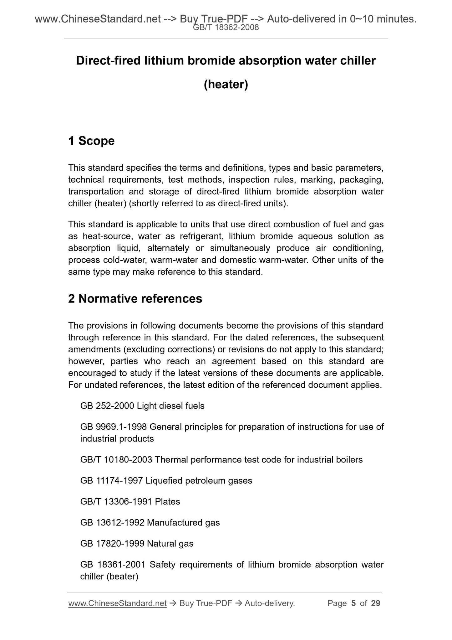
Direct-fired lithium bromide absorption water chiller
(heater)
1 Scope
This standard specifies the terms and definitions, types and basic parameters,
technical requirements, test methods, inspection rules, marking, packaging,
transportation and storage of direct-fired lithium bromide absorption water
chiller (heater) (shortly referred to as direct-fired units).
This standard is applicable to units that use direct combustion of fuel and gas
as heat-source, water as refrigerant, lithium bromide aqueous solution as
absorption liquid, alternately or simultaneously produce air conditioning,
process cold-water, warm-water and domestic warm-water. Other units of the
same type may make reference to this standard.
2 Normative references
The provisions in following documents become the provisions of this standard
through reference in this standard. For the dated references, the subsequent
amendments (excluding corrections) or revisions do not apply to this standard;
however, parties who reach an agreement based on this standard are
encouraged to study if the latest versions of these documents are applicable.
For undated references, the latest edition of the referenced document applies.
GB 252-2000 Light diesel fuels
GB 9969.1-1998 General principles for preparation of instructions for use of
industrial products
GB/T 10180-2003 Thermal performance test code for industrial boilers
GB 11174-1997 Liquefied petroleum gases
GB/T 13306-1991 Plates
GB 13612-1992 Manufactured gas
GB 17820-1999 Natural gas
GB 18361-2001 Safety requirements of lithium bromide absorption water
chiller (beater)
3.6
Nominal flowrate
The flowrate of water, fuel, etc. when the unit is subject to cooling capacity
and heating capacity test. Unit: m3/h, L/h or kg/h.
3.7
Maximum application pressure
The maximum pressure for the safe use of gas, fuel, water, etc., to be
guaranteed by the structural strength of the unit. Unit: MPa.
3.8
Rated pressure drop
The pressure loss value as generated by the rated flowrate of cold-water,
warm-water, chilling water, etc. when passing through the unit. Unit: MPa.
3.9
Supporting facilities
A fuel system, a water pump, a cooling tower, a flue, a water piping attached
to the outside of the direct-fired unit.
4 Type and basic parameters
4.1 Type
4.1.1 Classification by usage performance
a) Cooling-only type: The direct-fired unit which only supplies cold-water.
b) Cooling and heating type: The direct-fired unit which alternatively or
simultaneously supplies cold-water and warm-water.
4.1.2 Classification by fuel
a) Gas type: A unit that uses artificial gas, liquefied petroleum gas, natural
gas, other gaseous fuels.
b) Fuel type: A unit that uses liquid fuel such as light diesel oil or heavy diesel
oil.
4.2 Basic parameters
power consumption.
5.3.5 The measured coefficient of performance of the unit shall not be less than
95% of the nominal coefficient of performance.
5.3.6 The pressure drop of cold (hot) water and cooling-water of the unit shall
not exceed 110% of the rated pressure drop.
5.3.7 The leakage rate of the unit shall not exceed 2.03 x 10⁻⁶ Pa•m3/s.
5.3.8 The pipeline at water-side of the unit shall be free from abnormal
deformation or water leakage.
5.3.9 The noise of the unit shall comply with environmental protection
regulations and design requirements.
5.3.10 The safety performance of the unit: the pressure resistance, airtightness,
insulation resistance, withstanding voltage strength, electromagnetic
compatibility, performance of the combustion equipment, the action of the
safety protection device of the fuel piping system shall comply with the
requirements of GB 18361-2001.
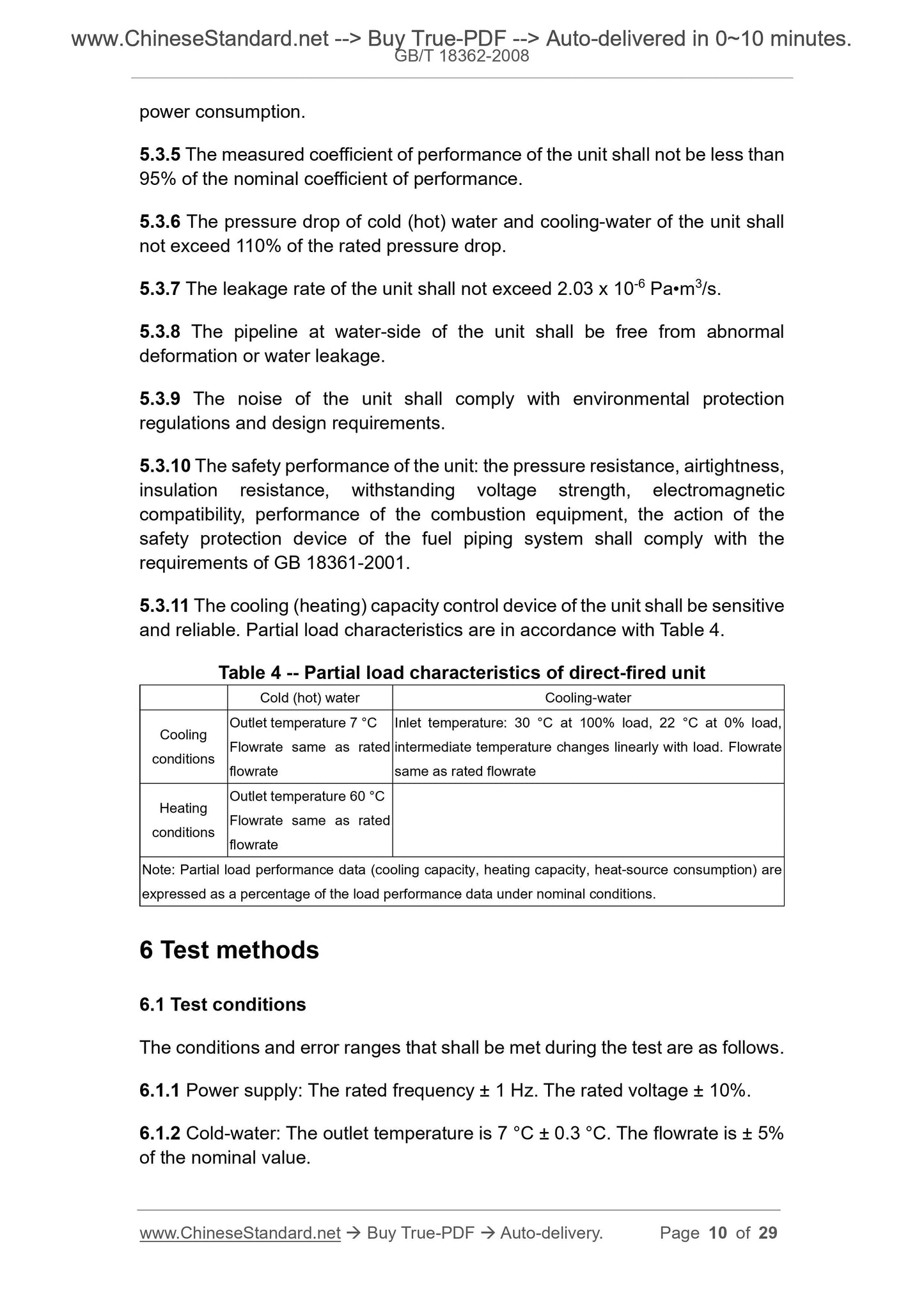
5.3.11 The cooling (heating) capacity control device of the unit shall be sensitive
and reliable. Partial load characteristics are in accordance with Table 4.
Table 4 -- Partial load characteristics of direct-fired unit
Cold (hot) water Cooling-water
Cooling
conditions
Outlet temperature 7 °C
Flowrate same as rated
flowrate
Inlet temperature: 30 °C at 100% load, 22 °C at 0% load,
intermediate temperature changes linearly with load. Flowrate
same as rated flowrate
Heating
conditions
Outlet temperature 60 °C
Flowrate same as rated
flowrate
Note: Partial load performance data (cooling capacity, heating capacity, heat-source consumption) are
expressed as a percentage of the load performance data under nominal conditions.
6 Test methods
6.1 Test conditions
The conditions and error ranges that shall be met during the test are as follows.
6.1.1 Power supply: The rated frequency ± 1 Hz. The rated voltage ± 10%.
6.1.2 Cold-water: The outlet temperature is 7 °C ± 0.3 °C. The flowrate is ± 5%
of the nominal value.
6.3.6 Pressure loss at water-side
When the value of the cooling capacity is stable in the test of 6.3.1 and the
value of the heating capacity is stable in the test of 6.3.2, use the method and
formula as shown in Appendix C to calculate the pressure loss at the cold-water
side, the cooling-water side, or the warm-water side.
6.3.7 Airtightness of chiller
After passing the leak testing by the use of dry clean air or nitrogen foaming as
well as the pressure holding test, use the helium mass spectrometer for leak
detection:
a) Connect the unit to the helium mass spectrometer and the supporting
vacuum pump. After vacuuming to the required vacuum level of the helium
mass spectrometer, directly spray the helium gas on the unit's possible
leaks (welds, seals, etc.), use the helium mass spectrometer to make
partial leak detection of the unit;
b) Place the unit in the hood, connect the helium mass spectrometer to the
supporting vacuum pump. After vacuuming to the required vacuum level
of the helium mass spectrometer, turn off the supporting vacuum pump.
Fill helium gas in the gas hood. Use the helium mass spectrometer to
detect the overall leak rate of the unit.
6.3.8 Pressure resistance at water-side
Use a clean water of not less than 5 °C to empty the air from the water-side, to
carry out pressure resistance test. The test pressure is 1.25 times the design
pressure. Apply the pressure for more than 10 minutes. Carry out inspection.
The results shall comply with the provisions of 5.3.8. After completing the test,
empty the water and blow it dry.
6.3.9 Noise
When the value of the cooling capacity is stable in the test of 6.3.1, use the
method of JB/T 4330-1999 to determine and calculate the noise of unit.
6.3.10 Safety performance
The test of pressure resistance, airtightness, insulation resistance, withstanding
voltage strength, electromagnetic compatibility, performance of combustion
equipment, action of safety protection devices of the fuel piping system shall be
carried out in accordance with the method as specified in GB 18361-2001.
6.3.11 Partial load characteristics
a) Proportional control
e) Date of manufacture.
8.1.2 The relevant parts of the unit shall be marked with signs of operation
status (such as direction change, flow direction, etc.). For places that are prone
to human injury (such as high-temperatures, etc.), it shall be attached with a
prominent safety mark.
8.1.3 Units which are exit-factory with filled absorbent liquid shall be clearly
marked.
8.2 Packaging
8.2.1 The unit shall take anti-rust measures. Randomly exit-factory parts shall
be rust-proof and fixed in the packaging box.
8.2.2 If the unit is exit-factory as a whole, it shall be filled with 0.01 MPa ~ 0.03
MPa of nitrogen or kept under vacuum before packaging.
8.2.3 The following documents shall be included in the exit-factory packaging
of each unit:
8.2.3.1 Product certification.
8.2.3.2 Instructions for installation and use. The content shall meet the
requirements of GB 9969.1-1998, including:
a) Signage content and other technical parameters (pressure loss at water-
side, geometric size, solution filling volume, operating mass, etc.);
b) Instructions, requirements and precautions for product transportation,
storage, installation;
c) Precautions for use and maintenance instructions. Its contents are as
shown in Appendix D.
8.2.3.3 Packing list.
8.3 Transportation and storage
8.3.1 During transportation and storage of the unit, it shall take the anti-rust
measures. It shall be stored in covered areas.
8.3.2 The valve connecting the unit to the atmosphere shall not be easily
opened.
8.3.3 The exposed threaded joint of the unit is plugged by bolts and the flange
holes are covered with blind plates, to prevent debris from entering.
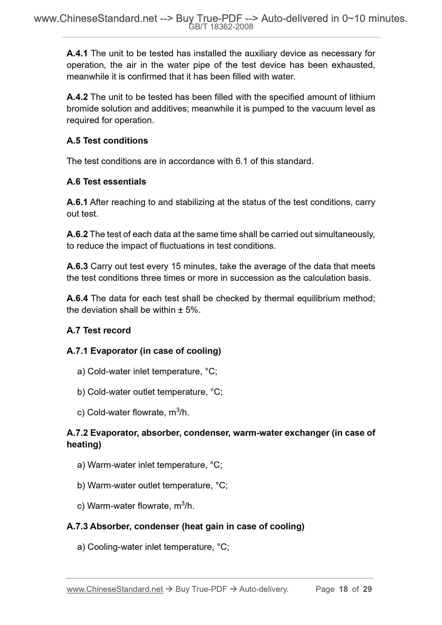
A.4.1 The unit to be tested has installed the auxiliary device as necessary for
operation, the air in the water pipe of the test device has been exhausted,
meanwhile it is confirmed that it has been filled with water.
A.4.2 The unit to be tested has been filled with the specified amount of lithium
bromide solution and additives; meanwhile it is pumped to the vacuum level as
required for operation.
A.5 Test conditions
The test conditions are in accordance with 6.1 of this standard.
A.6 Test essentials
A.6.1 After reaching to and stabilizing at the status of the test conditions, carry
out test.
A.6.2 The test of each data at the same time shall be carried out simultaneously,
to reduce the impact of fluctuations in test conditions.
A.6.3 Carry out test every 15 minutes, take the average of the data that meets
the test conditions three times or more in succession as the calculation basis.
A.6.4 The data for each test shall be checked by thermal equilibrium method;
the deviation shall be within ± 5%.
A.7 Test record
A.7.1 Evaporator (in case of cooling)
a) Cold-water inlet temperature, °C;
b) Cold-water outlet temperature, °C;
c) Cold-water flowrate, m3/h.
A.7.2 Evaporator, absorber, condenser, warm-water exchanger (in case of
heating)
a) Warm-water inlet temperature, °C;
b) Warm-water outlet temperature, °C;
c) Warm-water flowrate, m3/h.
A.7.3 Absorber, condenser (heat gain in case of cooling)
a) Cooling-water inlet temperature, °C;
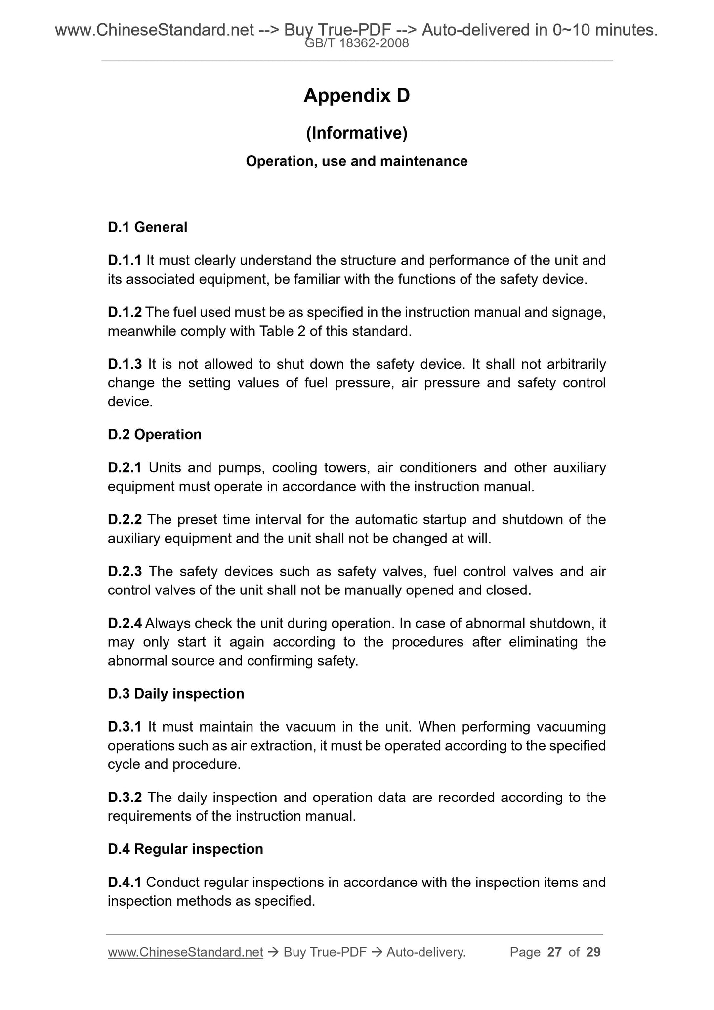
Appendix D
(Informative)
Operation, use and maintenance
D.1 General
D.1.1 It must clearly understand the structure and performance of the unit and
its associated equipment, be familiar with the functions of the safety device.
D.1.2 The fuel used must be as specified in the instruction manual and signage,
meanwhile comply with Table 2 of this standard.
D.1.3 It is not allowed to shut down the safety device. It shall not arbitrarily
change the setting values of fuel pressure, air pressure and safety control
device.
D.2 Operation
D.2.1 Units and pumps, cooling towers, air conditioners and other auxiliary
equipment must operate in accordance with the instruction manual.
D.2.2 The preset time interval for the automatic startup and shutdown of the
auxiliary equipment and the unit shall not be changed at will.
D.2.3 The safety devices such as safety valves, fuel control valves and air
control valves of the unit shall not be manually opened and closed.
D.2.4 Always check the unit during operation. In case of abnorma...
View full details