Skip to product information
1 of 6

PayPal, credit cards. Download editable-PDF and invoice in 1 second!

GB/T 18144-2008 English PDF (GBT18144-2008)

GB/T 18144-2008 English PDF (GBT18144-2008)

Regular price $70.00 USD
Regular price Sale price $70.00 USD
Sale Sold out
Shipping calculated at checkout.
Delivery: 3 seconds. Download true-PDF + Invoice.
Get QUOTATION in 1-minute: Click GB/T 18144-2008
Historical versions: GB/T 18144-2008
Preview True-PDF (Reload/Scroll if blank)

GB/T 18144-2008: Test method for measurement of stress in glass
GB/T 18144-2008
GB
ICS 81.040.20
Q 33
NATIONAL STANDARD
OF THE PEOPLE’S REPUBLIC OF CHINA
Replacing GB/T 18144-2000
Test method for measurement of stress
in glass
ISSUED ON. OCTOBER 15, 2008
IMPLEMENTED ON. JUNE 1, 2009
Issued by.
General Administration of Quality Supervision, Inspection
and Quarantine of the People’s Republic of China;
Standardization Administration of the People’s Republic of
China
Table of Contents
Foreword ... 3
1 Scope ... 4
2 Normative references ... 4
3 Terms and definitions ... 4
4 Test Method ... 5
Foreword
The consistency of this standard with the ASTM standard ASTM C1279-05 Test Method for
Non-Destructive Photoelastic Measurement of Surface and Edge Stresses in Annealed Glass,
Half-Toughened Glass, and Toughened Glass, ASTM C1048-04 Heat-Strengthened Flat
Glass-HS Class, FT Class Coating and Non-Coating Glass , and Japanese industrial
technology standard JIS R3222-2003 Half-Toughened glass IS NOT equivalent.
This standard replaces GB/T 18144-2000 Test method for measurement of stress in glass.
This standard, in comparison with GB/T 18144-2000, has the major changes as follows.
— In Chapter “Scope”, ADD laminated glass used in car’s front windshield and hot
bending glass, DELETE annealed glass;
— ADD nondestructive test method for measurement of edge stress in glass with
coating;
— Specific values of instrument constants of the surface stress meter and edge stress
meter are not described in the standard.
This Standard was proposed by China Building Materials Federation.
This standard shall be centralized by the National Architectural Glass Standardization
Technical Committee.
Drafting organization of this standard. China Building Material Test and Certification Center.
The main drafters of this standard. Xiao Pengjun, Wang Jingjing, and Lu Fan.
The previous version replaced by this standard is as follows.
— GB/T 18144-2000.
Test method for measurement of stress in glass
1 Scope
This standard specifies the definitions and methods related to the tests on surface stress
and edge stress of glass. In this standard, the method of surface stress test is suitable for
toughened glass and half-toughened glass made of float glass. The method of edge
stress test is fit for toughened glass, half-toughened glass, laminated glass of car’s front
windshield, and hot bending glass.
For chemical toughened glass, it may refer to the method of surface stress test in this
standard.
This test method is a nondestructive test method.
2 Normative references
The articles contained in the following documents have become part of this standard when
they are quoted herein. For the dated documents so quoted, all the modifications
(excluding corrections) or revisions made thereafter shall not be applicable to this
Standard. For the undated documents so quoted, the latest edition shall be applicable to
this Standard.
JC/T 632 Road vehicles - Safety glazing materials - Terminology
3 Terms and definitions
For the purpose of this standard, the following terms and definitions and those defined in
JC/T 632 apply.
3.1
Polarizer
A kind of optical device, through which natural light becomes plane-polarized light with a
certain vibration direction, and which is usually placed between the light source and
samples under test.
4.2.3 Sample
Use the finished products as the sample. In order to avoid the generation of thermal stress,
the internal and external temperatures of the sample shall be same to each other and
same as the ambient temperature.
4.2.4 Determination of the edge stress measuring points
Measurement points of edge stress shall take the center position of each side.
4.2.5 Test procedures
a) After connecting to the light source of the instrument, make the polarizer and
analyzer vertical to each other and make it stay at the initial position. At this time,
the observation field shall be uniformly dark.
b) Put the measured sample between the polarizer and 1/4 wave plate. Make the
primary stress direction angulated at 45 degrees to the sample the polarization axial
direction. Under such situation, the light interference figure generated by the stress
can be seen at the edge of the sample in the observation field, as shown in Figure 4
a). There is a bold black stripe parallel to the edge at a certain distance away from
the edge, where the stress is zero. The comprehensive stress in the area under the
black stripe is pressure stress. The comprehensive stress in the area above the
black stripe is pulling stress. The direction of the pressure stress or pulling stress
can also be determined by the rotation direction in the compensation of the analyzer.
The analyzer rotating to "+" means that the testing stress is pulling stress, and
conversely, rotating to "-" means that the testing stress is pressure stress.
c) Rotate the analyzer to "-" to make the center line of the zero order of the black stripe
move to the edge of the sample, as shown in Figure 4 b). At this time, it can obtain
the corresponding turning angle of the maximum edge compressive stress. If the
sample’s edge is grinded or chamfered, and the value of θ cannot be got directly,
measurement can be done at the area with the same distance to the sample’s edge
to get the rotation angle and then to get the value of θ with the extension line (For
example, if the grinded thickness is 0.4 mm away from the edge, measure the
corresponding angles in the areas 0.5 mm, 1.0 mm, 1.5 mm, 2.0 mm and 2.5 mm
away from the edge, connect each point with smooth curve and extend to intersect
a) Switch on the instrument, adjust relative position of the polarizer and the analyzer to
make the incoming light and the reflective light be at a proper angle. And adjust the
illumination diameter on the surface of the glass sample to about 100 mm.
b) Adjust the light axis of the polarizer and analyzer to make them vertical to each other
and at 45° to the direction of the sample’s principal stress.
c) Same as 4.2.5 c) -f).
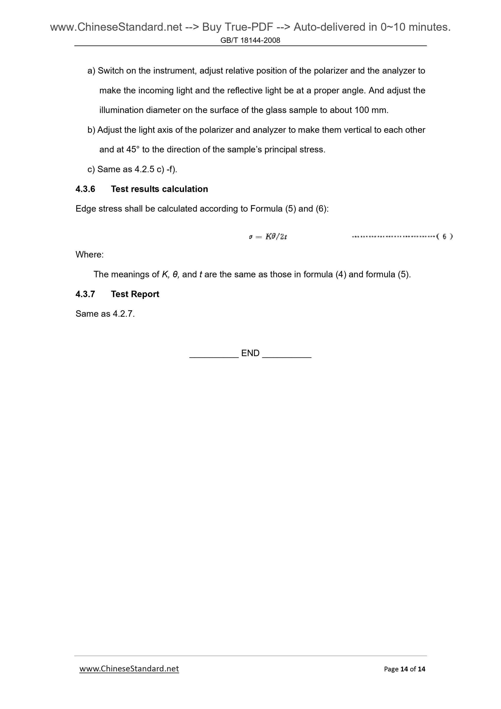
4.3.6 Test results calculation
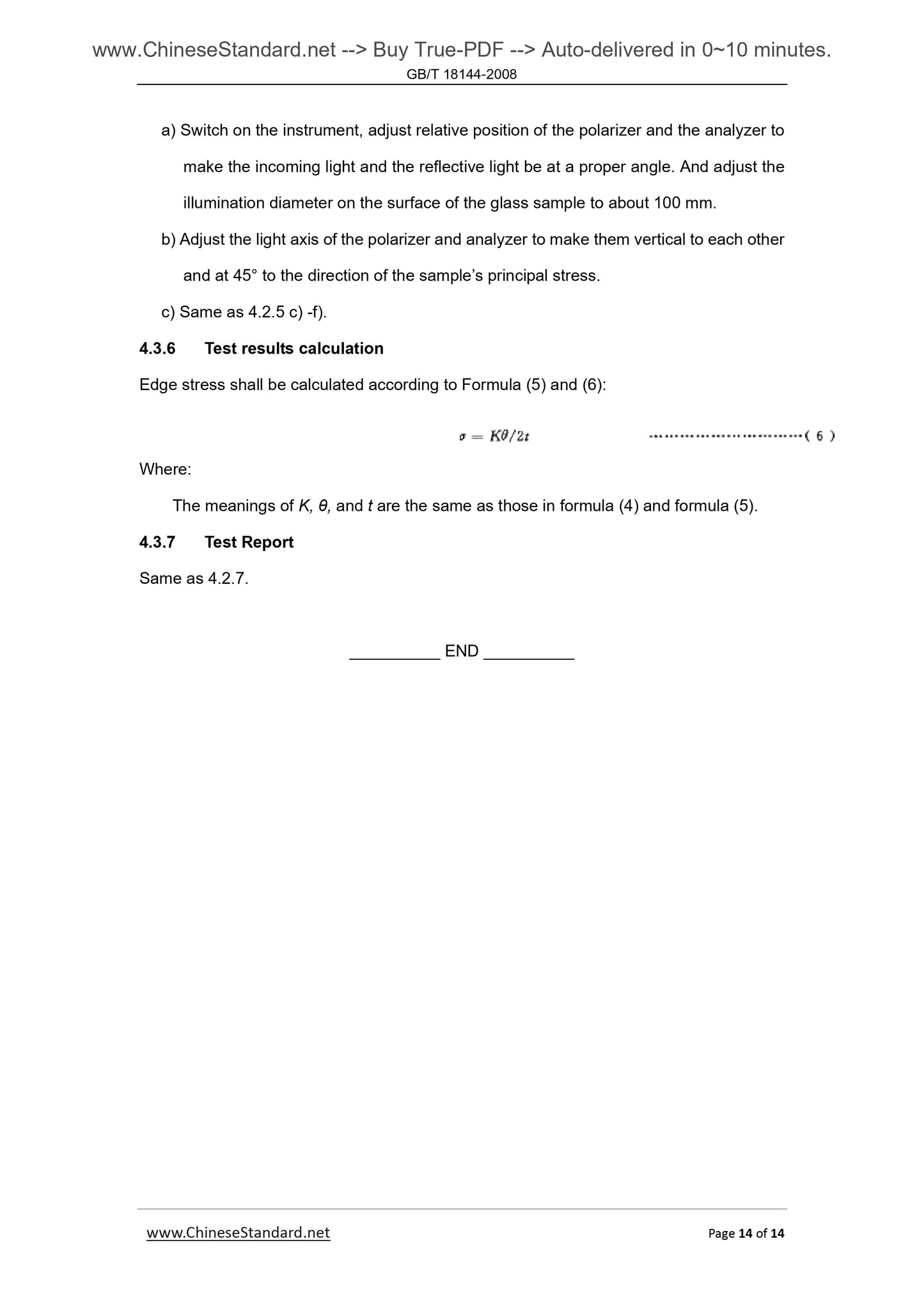
Edge stress shall be calculated according to Formula (5) and (6).
Where.
The meanings of K, θ, and t are the same as those in formula (4) and formula (5).
4.3.7 Test Report
Same as 4.2.7.

View full details