Skip to product information
1 of 12

www.ChineseStandard.us -- Field Test Asia Pte. Ltd.

GB/T 17851-2022 English PDF (GB/T17851-2022)

GB/T 17851-2022 English PDF (GB/T17851-2022)

Regular price $1,145.00
Regular price Sale price $1,145.00
Sale Sold out
Shipping calculated at checkout.
GB/T 17851-2022: Geometrical product specifications (GPS) - Geometrical tolerancing - Datums and datum systems
Delivery: 9 seconds. Download (& Email) true-PDF + Invoice.
Get Quotation: Click GB/T 17851-2022 (Self-service in 1-minute)
Historical versions (Master-website): GB/T 17851-2022
Preview True-PDF (Reload/Scroll-down if blank)

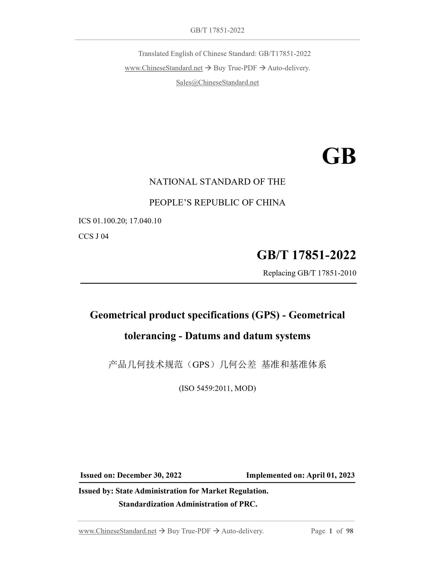
GB/T 17851-2022
GB
NATIONAL STANDARD OF THE
PEOPLE’S REPUBLIC OF CHINA
ICS 01.100.20; 17.040.10
CCS J 04
Replacing GB/T 17851-2010
Geometrical product specifications (GPS) - Geometrical
tolerancing - Datums and datum systems
(ISO 5459:2011, MOD)
ISSUED ON: DECEMBER 30, 2022
IMPLEMENTED ON: APRIL 01, 2023
Issued by: State Administration for Market Regulation.
Standardization Administration of PRC.
Table of Contents
Foreword ... 4
1 Scope ... 8
2 Normative references ... 8
3 Terms and definitions ... 9
4 Symbols ... 16
5 The role of datums ... 17
6 General concepts ... 20
6.1 General... 20
6.2 Intrinsic characteristics of the association surface established by datum features ... 23
6.3 Single datum, common datum, datum system ... 24
7 Graphic language ... 29
7.1 General... 29
7.2 Marking of datum features ... 29
7.3 Specification of datums and datum systems ... 34
7.4 Meaning of annotations and rules ... 34
Appendix A (Normative) Association of datum ... 52
A.1 Basic concepts ... 52
A.2 Association method ... 53
Appendix B (Informative) Invariance class ... 63
Appendix C (Informative) Example 1) ... 65
C.1 Example of single datum ... 65
C.2 Example of common datum ... 77
C.3 Example of datum system ... 84
Appendix D (Informative) Abolished marking method ... 88
D.1 Marking of specific cross-sections of cylinders as datum features ... 88
D.2 Marking of datum target line ... 88
D.3 Marking of common datums ... 89
Appendix E (Informative) Examples of datum systems or common datums established
by contacting features ... 90
E.1 Example 1 ... 90
E.2 Example 2 ... 91
E.3 Example 3 ... 92
E.4 Example 4 ... 93
E.5 Example 5 ... 94
Appendix F (Normative) Relationships and dimensions of graphic symbols ... 95
Appendix G (Informative) Relationship to matrix model ... 96
G.1 Overview ... 96
G.2 Information about standards and their use ... 96
G.3 Location in GPS matrix model ... 96
G.4 Related standards ... 97
References ... 98
Geometrical product specifications (GPS) - Geometrical
tolerancing - Datums and datum systems
1 Scope
This document specifies the terminology, rules and methods related to the marking and
understanding of datums and datum systems in product technical documentation. This
document also provides corresponding explanations of the concepts involved to
facilitate understanding.
This document defines a set of normative operations for establishing datums and datum
systems (see GB/T 24637.2). Its inspection operation set (see GB/T 24637.2) can take
different forms (physical simulation or mathematical association); however, this is not
the content discussed in this document.
Note: GB/T 16671 gives detailed rules on the maximum material requirements and minimum
material requirements of the datum.
This document applies to product geometric technical specifications related to datums
and datum systems.
2 Normative references
The contents of the following documents constitute essential provisions of this
document through normative references in the text. Among them, for dated reference
documents, only the version corresponding to the date applies to this document; for
undated reference documents, the latest version (including all amendments) applies to
this document.
GB/T 1182-2018 Geometrical product specifications (GPS) - Geometrical
tolerancing - Tolerances of form, orientation, location and run-out (ISO 1101:2017,
MOD)
GB/T 16671-2018 Geometrical product specifications (GPS) - Geometrical
tolerancing - Maximum material requirement (MMR), least material requirement
(LMR) and reciprocity requirement (RPR) (ISO 2692:2014, MOD)
GB/T 24637.1 Geometrical product specifications (GPS) - General concepts - Part
1: Model for geometrical specification and verification (GB/T 24637.1-2020, ISO
17450-1:2011, MOD)
- Composite surface (e.g. a free-shaped curved surface).
Each single feature or collection feature belongs to an invariance class (see Appendix
B for explanations of invariance class, degrees of invariance, degrees of freedom).
Association features are established from actual single datum features or extracted
single datum features. Association features can be determined through association,
which include constraints on the feature itself or constraints relative to one or more
other features. The orientation features that constitute the datum are determined by
these association features. See Appendix A for the default association method.
One or more single features can be used to establish a datum. If only a single feature is
used, a single datum is established. If multiple single features are used, these features
may either be considered simultaneously to establish a common datum, OR they may
be established in a defined order to establish a datum system (see 6.3).
All datum features used to establish datums shall be clearly marked.
A single datum (see 6.3.2), a common datum (see 6.3.3) or a datum system (see 6.3.4)
in the geometric specification shall be clearly defined.
For the association, if any additional constraints are required, they shall be defined.
Note 1: Datums and datum systems are geometric features, not coordinate systems. Coordinate
systems can be established on datums.
Note 2: This document does not provide the expression of the coordinate system. This part of
the content may be added in subsequent versions or amendments of GB/T 17851.
Example: The single datum marked in Figure 4 is derived from actual features that are
cylindrical in the nominal state, which is used to orient or locate the tolerance zone. In order to
export this datum, the following shall be done:
- Separation: To determine the actual composition surfaces corresponding to the nominal
features [see Figure 4b)];
- Extraction: To obtain the extracted integral features [see Figure 4c)];
- Filtering: See Appendix A;
- Association: (Association method according to Appendix A) to determine the association
features. (In this example, the association features are of the same type as the nominal
features) Fit features [see Figure 4d)] are established from non-ideal surfaces (in the
specification operation set) or from extracted features (in the inspection operation set).
The datum is the situation feature (axis) of the association cylinder [see Figure 4e)].
The intrinsic characteristics introduced by the combination of features (determining the
relationship between association features), by default, shall maintain their theoretically
correct linear and angular dimensions.
Example: The common datum is established by two parallel cylinders with different axes
(Invariance class: Prismatic). Every single cylinder has one intrinsic characteristic: its diameter.
The combination of these two features also has intrinsic characteristics: the angle determined
by the actual two axes limits the torsion of the datum; the distance between the two axes (see
C.2.4). By default, the diameters of the two cylinders are variable; the torsion angle and distance
between the two cylinders remain theoretically correct.
Note: In special cases, using the modifier [DV], the distance between features can be variable
when combined, see 6.3.3, 7.4.2.7, 7.4.2.9.
6.2.4 A datum system established by two or more single datum features in a
specified order
The intrinsic characteristics of each association feature used to establish the datum
system shall comply with the provisions in 6.2.2.
The intrinsic characteristics introduced by the combination of features (determining the
relationship between association features), by default, shall have variable linear
dimensions; however, the angular dimensions shall remain theoretically correct.
6.3 Single datum, common datum, datum system
6.3.1 General requirements
When a single surface or a collection surface is marked as a datum feature, the
invariance of these surfaces shall be compared and identified in accordance with Table
B.1, to confirm the type of the corresponding situation feature that constitutes the datum
(point, straight line, plane, spiral line, or a combination thereof).
6.3.2 Single datum
A single datum contains one or more situation features; its situation features can be
based on the entirety of a single feature or a part of a single feature.
Note: The single datum of a cone has two situation features: the axis of the cone and a point on
that axis.
If there is only one common datum in the tolerance frame, or the common datum is the
primary datum of the datum system, there are no external orientation constraints and
location constraints in the combination operation of the association features, when
establishing the datum. Therefore, these surfaces (forming the collection surface) are
associated together. For the constraint specification of the common datum as the
"secondary datum" or "tertiary datum", see 6.3.4.
If the primary datum is sufficient to constrain the degrees of freedom of the tolerance
zone, the secondary datum shall not be given.
If the primary datum and the secondary datum are sufficient to constrain the degree of
freedom of the tolerance zone, the tertiary datum shall not be given.
6.3.4 (Examples 1 and 2 illustrate the difference between datum systems and common
datums through examples) and C.2 give examples of common datums.
The supplementary symbol [DV] (meaning "distance variable") is marked after the
common datum letter, to indicate that the distance between the orientation features is
variable, see 7.4.2.9 and E.4.
6.3.4 Datum system
A datum system consists of two or three single datums or common datums in a specified
order. A datum system contains two or three orientation features, which are derived
from the corresponding datum features.
The orientation features for establishing the datum system need to be obtained in the
order specified by the geometric specifications. The associated surfaces maintain the
theoretically correct location and theoretically correct orientation relative to each other.
The order of the datum system determines the orientation and location constraints of
the association operation: the primary datum has orientation and location constraints on
the secondary datum; the secondary datum has orientation and location constraints on
the tertiary datum.
In addition to the primary datum constraining the degrees of freedom of the tolerance
zone, when another datum is required to constrain other degrees of freedom of the
tolerance zone, a secondary datum shall be given.
In addition to the primary datum and the secondary datum constraining the degrees of
freedom of the tolerance zone, when another datum is required to constrain other
degrees of freedom of the tolerance zone, a tertiary datum shall be given.
If the primary datum is sufficient to constrain the degree of freedom of the tolerance
zone, the second or tertiary datum shall not be given. If the primary datum and the
secondary datum are sufficient to constrain the degree of freedom of the tolerance zone,
the tertiary datum shall not be given.
Rules 6 and 7).
7.4.1.4 For a certain datum or each datum that constitutes a datum system, see the
following corresponding rules:
- If the association features are of different classes from the datum features
(contacting features), see Rule 5;
- If the size of the size feature remains fixed or variable, see Rule 2;
- If it needs to delete the constraints given by the datum, see Rules 8 and 9;
- If it needs to use other geometric modifiers ( , or ) to specify the datum,
see Rule 10.
7.4.1.5 To decode the meaning of a datum or datum system, the following steps shall
be followed:
- Read the tolerance frame to determine if a datum is used. If a tolerance frame has
more than two grids, at least one datum is used (see Rule 6).
- For the corresponding single datum or common datum part, read all datum letter
symbols (see Rule 7).
- For each datum letter symbol, identify the corresponding datum feature (see Rule
1).
- Determine whether the datum feature is the entire integral feature (see Rule 3). If
not, read the datum target and its definition (taking into account the theoretically
correct dimensions: see Rule 4).
- Consider how the association operation shall be performed when establishing a
datum (see Rules 2, 5, 6, 7, 8, 9, 10).
7.4.2 Rules
7.4.2.1 Rule 1 - Datum feature (established from a single feature)
Rule 1 is divided into two situations.
a) When the single feature used to establish the datum is a feature of size, datum
identifiers shall be placed to designate the corresponding surface as follows:
- Place it at the extension line of the dimension line [see Figure 18a)];
- Place it on the tolerance grid pointing to the extension of the surface dimension
line [see Figure 18b)];
The theoretically correct dimension as implied by intrinsic characteristics can only be
unmarked 0 mm, 0°, 90°, 180°, 270°.
Note 1: For intrinsic characteristics that maintain theoretically correct dimensions, see C.1.3;
for variable intrinsic characteristics, see C.1.2.
Note 2: GB/T 1804 and GB/T 1184 give more information about general (default) tolerances.
7.4.2.3 Rule 3 - Datum established from the entire feature
If a datum is established from the entire integral feature, only one datum identifier shall
be noted.
Note: See Figure 23a) and C.1.1.
7.4.2.4 Rule 4 - Datum established by one or more datum targets
If a datum target or multiple datum targets on the same surface are used to establish a
datum, the datum code corresponding to the surface shall be repeatedly marked near
the datum identifier, followed by the corresponding serial number (separated by
commas), to define corresponding datum target identifiers (see Figure 20). For each
single datum target, it shall mark the datum target identifier, datum code, serial number
of the datum target; appropriately note the dimensions of the datum target.
Figure 20 -- Datum marking established by datum target
If there is only one datum t...
View full details