1
/
of
5
www.ChineseStandard.us -- Field Test Asia Pte. Ltd.
GB/T 17738.2-2013 English PDF (GB/T17738.2-2013)
Regular price
$150.00
Regular price
Sale price
$150.00
Unit price
/
per
Shipping calculated at checkout.
Couldn't load pickup availability
GB/T 17738.2-2013: Radio frequency and coaxial cable assemblies -- Part 2: Sectional specification for flexible coaxial cable assemblies
Delivery: 9 seconds. Download (& Email) true-PDF + Invoice.
Get Quotation: Click GB/T 17738.2-2013 (Self-service in 1-minute)
Historical versions (Master-website): GB/T 17738.2-2013
Preview True-PDF (Reload/Scroll-down if blank)
GB/T 17738.2-2013
Radio frequency and coaxial cable assemblies.Part 2. Sectional specification for flexible coaxial cable assemblies
ICS 33.120.10
L26
National Standards of People's Republic of China
Replace GB/T 15866-1995
RF coaxial cable assembly
Part 2. sectional specification for flexible coaxial cable assemblies
Part 2. Sectionalspecificationforflexiblecoaxialcableassemblies
(IEC 60966-2-1..2008, IDT)
Released on.2013-12-17
2014-06-15 implementation
General Administration of Quality Supervision, Inspection and Quarantine of the People's Republic of China
China National Standardization Administration issued
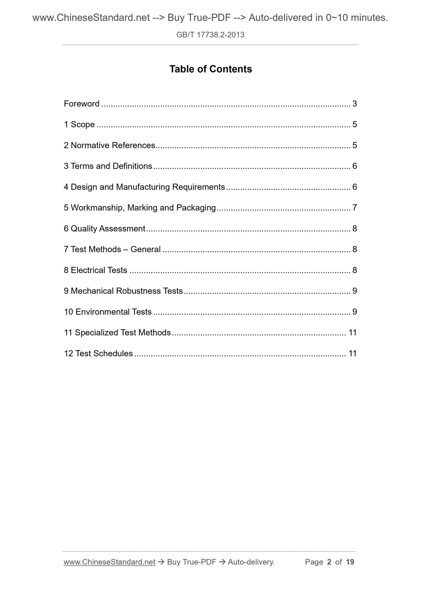
Content
Foreword I
1 range 1
2 Normative references 1
3 Terms and Definitions 1
4 Design and manufacturing requirements 1
5 Processing quality, signs and packaging 2
6 Quality Assessment 3
7 General Test Method 3
8 Electrical test 3
9 Mechanical strength test 4
10 Environmental Test 4
11 Special test methods 5
12 Test List 5
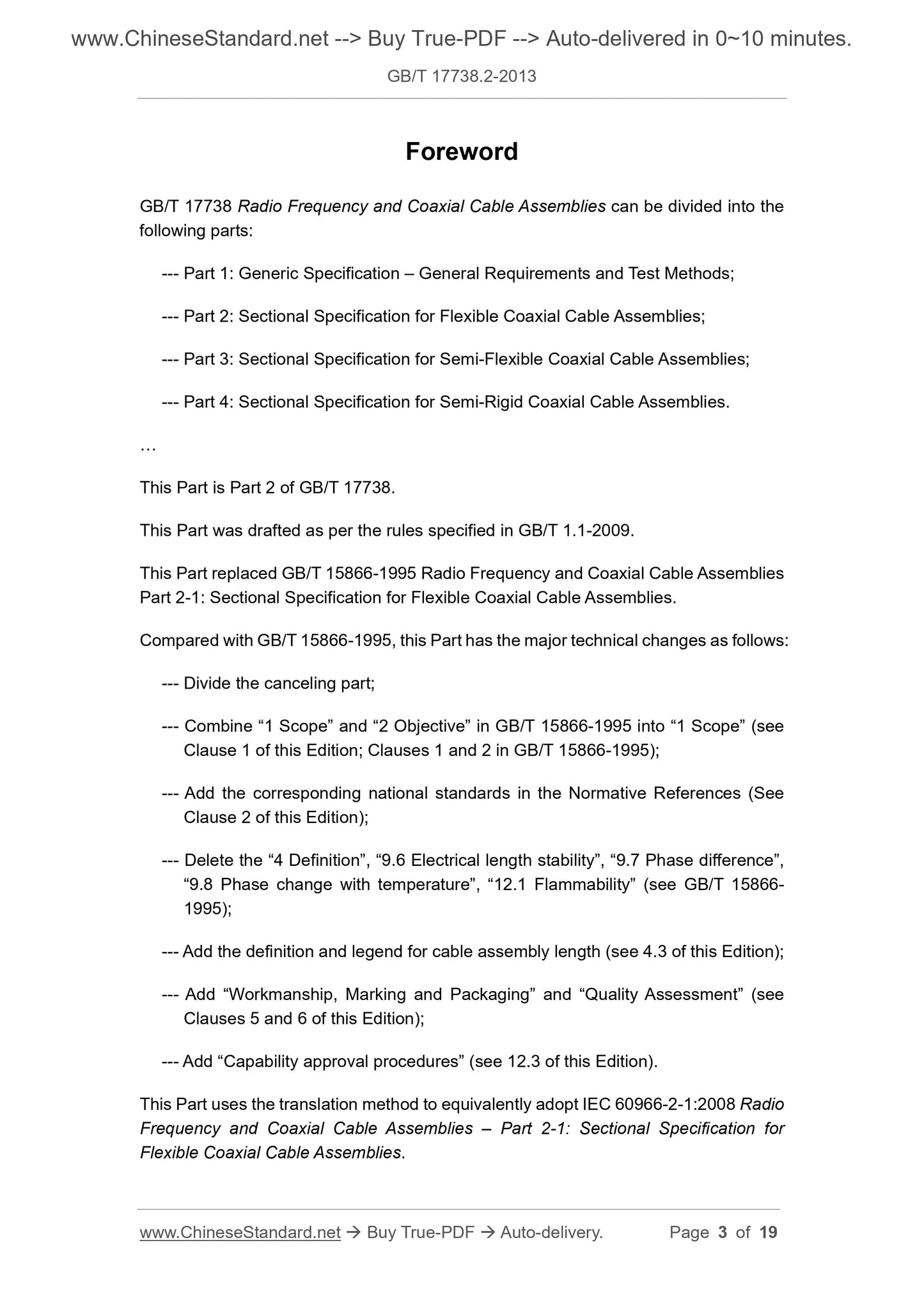
Foreword
GB/T 17738 "RF coaxial cable assembly" is divided into the following parts.
--- Part 1. General requirements and test methods for general specifications;
--- Part 2. Soft coaxial cable assembly sub-specification;
--- Part 3. Sub-standard for semi-flexible coaxial cable assemblies;
--- Part 4. Sub-standards for semi-rigid coaxial cable assemblies;
This part is the second part of GB/T 17738.
This part is drafted in accordance with the rules given in GB/T 1.1-2009.
This part replaces GB/T 15866-1995 "RF coaxial cable assemblies - Part 2-1. Soft RF coaxial cable assemblies.
Fan.
The main technical changes in this section compared with GB/T 15866-1995 are as follows.
--- The division of the withdrawal article;
--- Combine "1 range" and "2 purpose" in GB/T 15866-1995 into "1 range" (see Chapter 1, GB/T 15866-1995
Chapters 1 and 2);
--- The corresponding national standards have been added to the "normative references" (see Chapter 2);
--- Removed the "4 definition", "9.6 electrical length stability", "9.7 phase difference", "9.8 phase change with temperature" repeated with the general specification
", 12.1 flammability" (see GB/T 15866-1995);
--- Added definition and legend of cable assembly length (see 4.3);
--- Added "Processing Quality, Marking and Packaging" and "Quality Assessment" (see Chapters 5 and 6);
--- Added "Capability Approval Process" (see 12.3).
This section uses the translation method equivalent to IEC 60966-2-1.2008 "RF coaxial cable assemblies - Part 2-1. Soft RF coaxial
Cable assembly sub-specification.
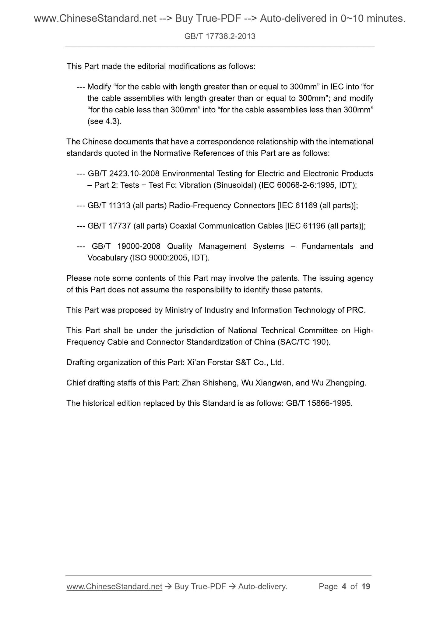
This section has made the following editorial changes.
--- Amend the IEC "for cables longer than or equal to 300mm" to "for electricity with a length greater than or equal to 300mm
"Cable assembly"; "For cables less than 300mm" is amended to "For cable assemblies less than 300mm" (see 4.3).
The documents of our country that have a consistent correspondence with the international documents referenced in this part are as follows.
GB/T 2423.10-2008 Environmental testing for electric and electronic products - Part 2. Test method test Fc. Vibration (sinusoidal)
(IEC 60068-2-6.1995, IDT);
---GB/T 11313 (all parts) RF connector [IEC 61169 (alparts)];
---GB/T 17737 (all parts) RF cable [IEC 61196 (alparts)];
---GB/T 19000-2008 Quality Management System Foundation and Terminology (ISO 9000.2005, IDT).
Please note that some of the content in this section may involve patents. The issuing organization of this section does not assume responsibility for identifying these patents.
This part was proposed by the Ministry of Industry and Information Technology of the People's Republic of China.
This part is under the jurisdiction of the National High-Tech Cable and Connector Standardization Technical Committee for Electronic Equipment (SAC/TC190).
This section drafted by. Xi'an Fujitec Technology Co., Ltd.
The main drafters of this section. Zhan Shisheng, Wu Xiangwen, Wu Zhengping.
The previous versions of the standards replaced by this section are. GB/T 15866-1995.
RF coaxial cable assembly
Part 2. sectional specification for flexible coaxial cable assemblies
1 Scope
This part of GB/T 17738 specifies a flexible coaxial cable assembly consisting of a flexible coaxial cable and a coaxial connector (hereinafter referred to as
Cable assemblies) Uniform requirements for electrical, mechanical and environmental performance testing.
This section applies to flexible coaxial cable assemblies that transmit transverse electromagnetic mode (TEM).
Note 1. This part of the cable assembly is always considered as a unit. All regulations apply to finished components and are not suitable for single, unassembled
Components.
Note 2. This part should be supplemented by detailed specifications, which should specify additional details required for specific applications, and do not require specific requirements for specific applications.
Some trials.
2 Normative references
The following documents are indispensable for the application of this document. For dated references, only dated versions apply to this article.
Pieces. For undated references, the latest edition (including all amendments) applies to this document.
Radio frequency coaxial cable assemblies - Part 1. General specification and test methods (IEC 60966-
1.1999, IDT)
GB/T 19000-2008 Quality Management System - Foundation and Terminology (ISO 9000.2005, IDT)
IEC 60068-2-6 Environmental testing - Part 2-6. Test test Fc. Vibration (sinusoidal) (Environmental testing -
Part 2-6. Tests- TestFc. Vibration(sinusoidal))
IEC 60410 count check sampling plan and program (Samplingplansandproceduresforinspectionbyattrib-
Utes)
IEC 61169 (alparts) RF connectors (Radio-frequencyconnectors)
IEC 61196 (alparts) RF Cables (Coaxialcommunicationcables)
IEC QC001002 (alparts) IEC Electronic Component Quality Assessment System (IEC Q) Rules of Procedure (QualityAssessment
SystemforElectronicComponents(IEC Q-Rulesofprocedure)
3 Terms and definitions
The terms and definitions defined in GB/T 17738.1-1999 apply to this document.
4 Design and manufacturing requirements
Chapter 4 of GB/T 17738.1-2013 is applicable.
Replace the content with.
4.1 Cable design and structure
The cable should comply with IEC 61196. When cable designs other than these standards are required, they should conform to detailed specifications.
Claim.
Manufacturers may use additional protective tubes or cables other than IEC 61196 when required to meet detailed specification requirements.
The materials used for the cable shall be given as engineering data in the detailed specification.
4.2 Connector design and structure
The connector should be in accordance with IEC 61169. When a connector design different from IEC 61169 is required, the interface should conform
The corresponding part of IEC 61169 (when applicable) shall meet the requirements of the detailed specification.
The materials used in the connectors shall be given as engineering data in the detailed specifications.
4.3 Shape and interface dimensions
The shape and interface dimensions shall be in accordance with the detailed specifications of the cable assembly.
The length is defined as the distance between the reference plane of the two connectors and the reference plane, unless otherwise specified in the detailed specification. For right angle connectors, length
It is the axis to the right angle connector (as shown in Figure 1).
If not specified in the detailed specification, the length tolerance is ±1% for cable assemblies with a length greater than or equal to 300 mm; for small
For 300mm cable assemblies, the length tolerance is ±3mm.
Figure 1 Cable assembly length definition
5 Processing quality, marking and packaging
Except as provided below, the provisions of Chapter 5 of GB/T 17738.1-2013 apply.
5.2 Mark
supplement.
The cable assembly manufactured in accordance with this section consists of a length of cable and two connectors. Cable assemblies are also available when specified in the detailed specification
To include the identification of components and interconnects (see Figure 2). Terminal caps and other accessories can also be specified.
Note. Sometimes the cable assembly consists of only a length of cable and a connector.
a When specified.
Figure 2 Cable assembly example
6 Quality assessment
Chapter 6 of GB/T 17738.1-2013 is applicable.
7 general test methods
Chapter 7 of GB/T 17738.1-2013 is applicable.
8 Electrical test
Except as provided below, Chapter 8 of GB/T 17738.1-2013 is applicable.
8.1.4 What should be specified in the detailed specification
supplement.
The return loss (Ar) parameter should be preferred. It is also possible to specify a reflection coefficient (r) or a voltage standing wave ratio (VSWR).
among them.
Ar=-20log10 r
VSWR=
1 r
1 r
8.4 Insertion loss stability
Replace the content with.
8.4.1 Purpose
The change in insertion loss is determined when the cable assemblies are subjected to bending and torsion, respectively.
8.4.2 Procedure
8.4.2.1 Bending
The test is carried out in accordance with 8.6.2.1 of GB/T 17738.1-2013 and the insertion loss (not phase) is tested.
8.4.2.2 Reverse
The test is carried out in accordance with 8.6.2.2 of GB/T 17738.1-2013 and the insertion loss (not phase) is tested.
8.4.4 What should be specified in the detailed specification
Replace the content with.
The following information should be given.
a) The dynamic bending radius of the cable (radius of the mandrel).
b) Perform a bending test according to Method 1 or Method 2.
c) Test frequency.
d) The maximum change in insertion loss.
9 Mechanical strength test
Chapter 9 of GB/T 17738.1-2013 is applicable.
10 Environmental test
Except as provided below, Chapter 10 of GB/T 17738.1-2013 is applicable.
10.2 Vibration, collision, impact
Replace the content with.
10.2.1 Vibration
10.2.1.1 Procedure
This test shall be carried out in accordance with the IEC 60068-2-6 test Fc.
Except as otherwise specified in the detailed specification, the severity of vibration shall be selected from D.2.1 of GB/T 17738.1-2013.
The preferred placement in the vibration test is shown in Figure 3. The cable assembly should be subjected to vibration in each of three vertical directions, one of which
The vertical direction should be parallel to the common axis of the connector. The continuity of the inner and outer conductors should be monitored during the test.
Figure 3 Priority placement in vibration test
10.2.1.2 Requirements
Cable assemblies shall be free from obvious cracks, damage and loose parts, and shall not exceed 1 μs electrical discontinuity.
After the test, the insertion loss and return loss should not exceed the specified limits.
10.2.1.3 What should be specified in the detailed specification
The following information should be given.
a) Installation and fixing details for cable assemblies.
Note. The cable length between the mounting plate and the mounting plate is an important variable related to the diameter. The fixing plate should be steel.
b) The curve and severity of the vibration, including duration, frequency range and acceleration amplitude or displacement amplitude.
10.2.2 Collision
This test shall be specified in the detailed specification when required.
For the recommended severity level, see D.2.2 in GB/T 17738.1-2013.
10.2.3 Impact
This test shall be specified in the detailed specification when required.
For the recommended severity level, see D.2.3 in GB/T 17738.1-2013.
10.3.1 Procedure
supplement.
The severity of the test specified in D.2.4 of GB/T 17738.1-2013 should be preferred.
10.4.1 Procedure
supplement.
The severity of the test is shown in D.2.5 of GB/T 17738.1-2013.
10.5.1 Procedure
supplement.
The severity of the test is shown in D.2.6 of GB/T 17738.1-2013.
11 special test methods
Chapter 11 of GB/T 17738.1-2013 is applicable.
12 test list
Except as provided below, Chapter 12 of GB/T 17738.1-2013 is applicable.
Replace the content with.
12.1 Overview
In addition to the electrical, mechanical and environmental test requirements, the detailed specification shall also specify the test items to be carried out and the corresponding inspection level and
Quality level and cycle. Wherever possible, the complete test group (eg Eb, Ep, Vt) in Table 1 should be specified instead of a single test.
Table 1 Standard test grouping
Recommended test group
Group clause test project
Recommended severity
Period IL AQL nc
Ba
7.2 Visual inspection batch by batch S3 4.0
7.3 Dimensional Inspection Batch by Batch S3 4.0
Eh
8.1 Reflection characteristics batch by batch II 1.0
8.3 Insertion loss by batch II 1.0
8.4 Insertion Loss Stability 3 years S3 4.0
Eb
8.10 Withstand voltage batch by batch II 1.0
8.11 Insulation resistance batch by batch II 1.0
8.12 Inner and outer conductor continuity batch by batch II 1.0
Ez 8.2 Impedance uniformity batch by batch II 1.0
Ep
8.5 Propagation time 100% by batch 2
8.6 Electrical length stability 1 year S3 4.0
8.7 Phase difference batch by batch 100% 2
8.8 Phase change with temperature 3 years a - 3 0 1
Ee 8.9 Shielding efficiency 3 years a - 3 0
Mn
9.1 Tension 3 years a - 3 0 1
9.2 Bending 3 years S3 4.0
9.3 Bending durability 3 years S3 4.0
9.4 Cable Assembly Compression for 3 Years S3 4.0
Vv 10.2 Vibration, collision, impact 3 years a - 3 0
Vc 10.3 Climate sequence 3 years a - 3 0
Vt
10.4 Steady-state damp heat for 3 years a -
10.5 Temperature changes rapidly for 3 years a -
10.6 Solvent resistant and contaminated fluid for 1 year a -
10.8 Salt spray and sulfur dioxide for 1 year a -
Vf
10.7 Immersion for 3 years a -
10.9 Dustproof 3 years a -
10.10 Flammability for 3 years a -
n---the number of test samples;
c---the number of qualified judgments;
IL---check level according to IEC 60410;
AQL---Qualified quality level according to IEC 60410.
Note 1. If the manufacturer wishes to perform separate simulation tests on the connectors and cables instead ...
Share