1
/
of
6
www.ChineseStandard.us -- Field Test Asia Pte. Ltd.
GB/T 17626.5-2019 English PDF (GB/T17626.5-2019)
GB/T 17626.5-2019 English PDF (GB/T17626.5-2019)
Regular price
$560.00
Regular price
Sale price
$560.00
Unit price
/
per
Shipping calculated at checkout.
Couldn't load pickup availability
GB/T 17626.5-2019: Electromagnetic compatibility - Testing and measurement techniques - Surge immunity test
Delivery: 9 seconds. Download (and Email) true-PDF + Invoice.Get Quotation: Click GB/T 17626.5-2019 (Self-service in 1-minute)
Newer / historical versions: GB/T 17626.5-2019
Preview True-PDF
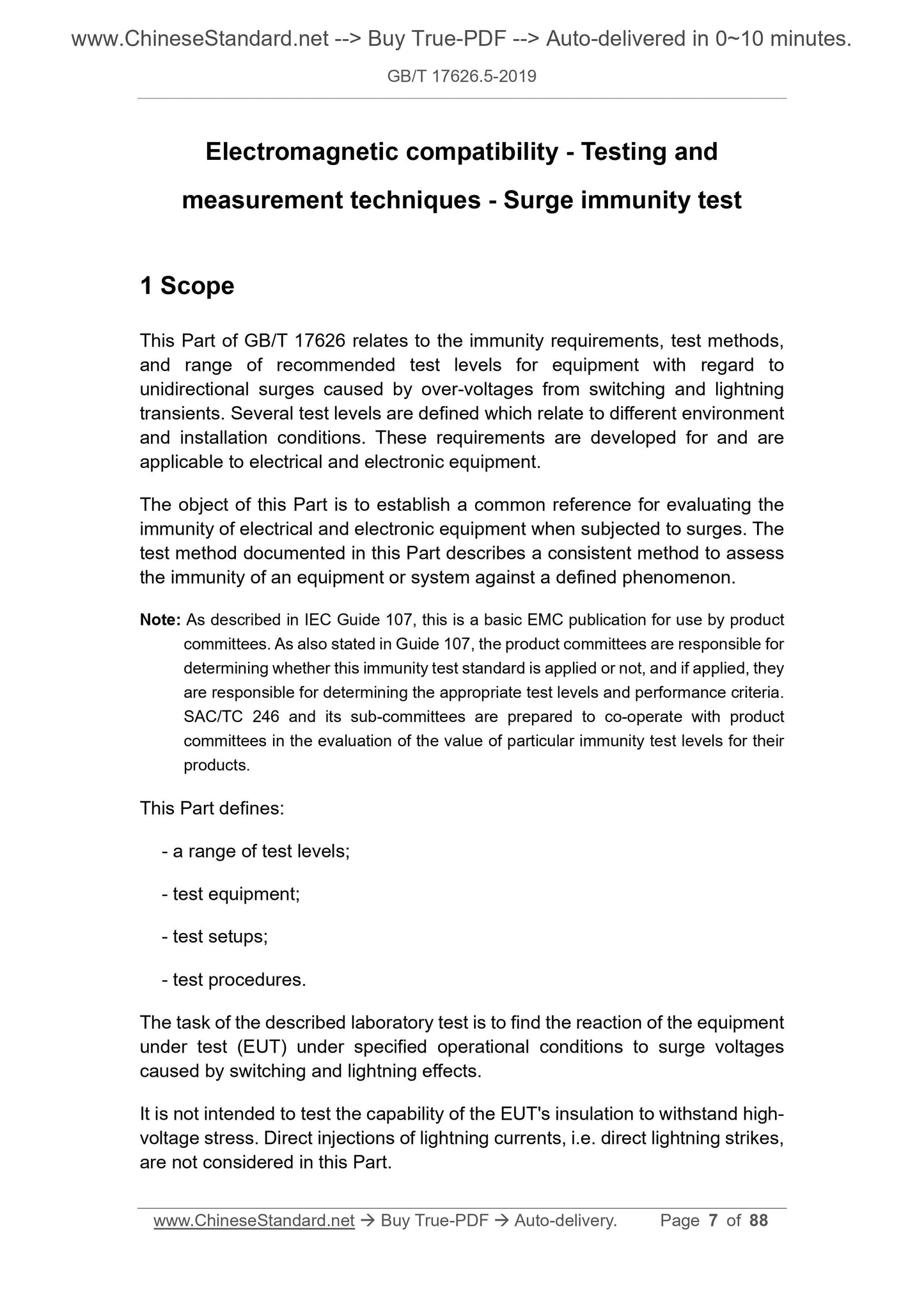
Scope
This Part of GB/T 17626 relates to the immunity requirements, test methods,and range of recommended test levels for equipment with regard to
unidirectional surges caused by over-voltages from switching and lightning
transients. Several test levels are defined which relate to different environment
and installation conditions. These requirements are developed for and are
applicable to electrical and electronic equipment.
Basic Data
| Standard ID | GB/T 17626.5-2019 (GB/T17626.5-2019) |
| Description (Translated English) | Electromagnetic compatibility - Testing and measurement techniques - Surge immunity test |
| Sector / Industry | National Standard (Recommended) |
| Classification of Chinese Standard | L06 |
| Classification of International Standard | 33.100.20 |
| Word Count Estimation | 60,651 |
| Date of Issue | 2019-06-04 |
| Date of Implementation | 2020-01-01 |
| Issuing agency(ies) | State Administration for Market Regulation, China National Standardization Administration |
Share