1
/
of
7
PayPal, credit cards. Download editable-PDF and invoice in 1 second!
GB/T 17626.4-2008 English PDF (GB/T17626.4-2008)
Regular price
$105.00
Regular price
Sale price
$105.00
Unit price
/
per
Shipping calculated at checkout.
Couldn't load pickup availability
GB/T 17626.4-2008: Electromagnetic compatibility -- Testing and measurement techniques -- Electrical fast transient/burst immunity test
Delivery: 9 seconds. Download (and Email) true-PDF + Invoice.
Newer version: (Replacing this standard) GB/T 17626.4-2018
Get Quotation: Click GB/T 17626.4-2008 (Self-service in 1-minute)
Historical versions (Master-website): GB/T 17626.4-2018
Preview True-PDF (Reload/Scroll-down if blank)
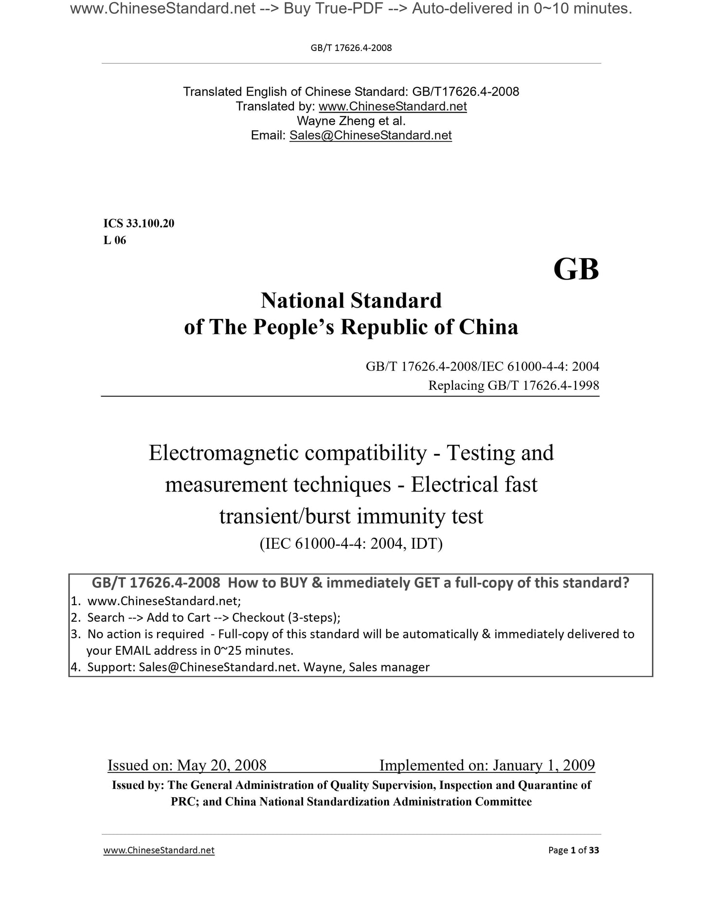
GB/T 17626.4-2008
Electromagnetic compatibility-Testing and measurement techniques-Electrical fast transient/burst immunity test
ICS 33.100.20
L06
National Standards of People's Republic of China
Replacing GB/T 17626.4-1998
Electromagnetic compatibility test and measurement technology
Immunity test of electrical fast transient pulse group
2008-05-20 released
2009-01-01 implementation
General Administration of Quality Supervision, Inspection and Quarantine of the People's Republic of China
Issued by China National Standardization Management Committee
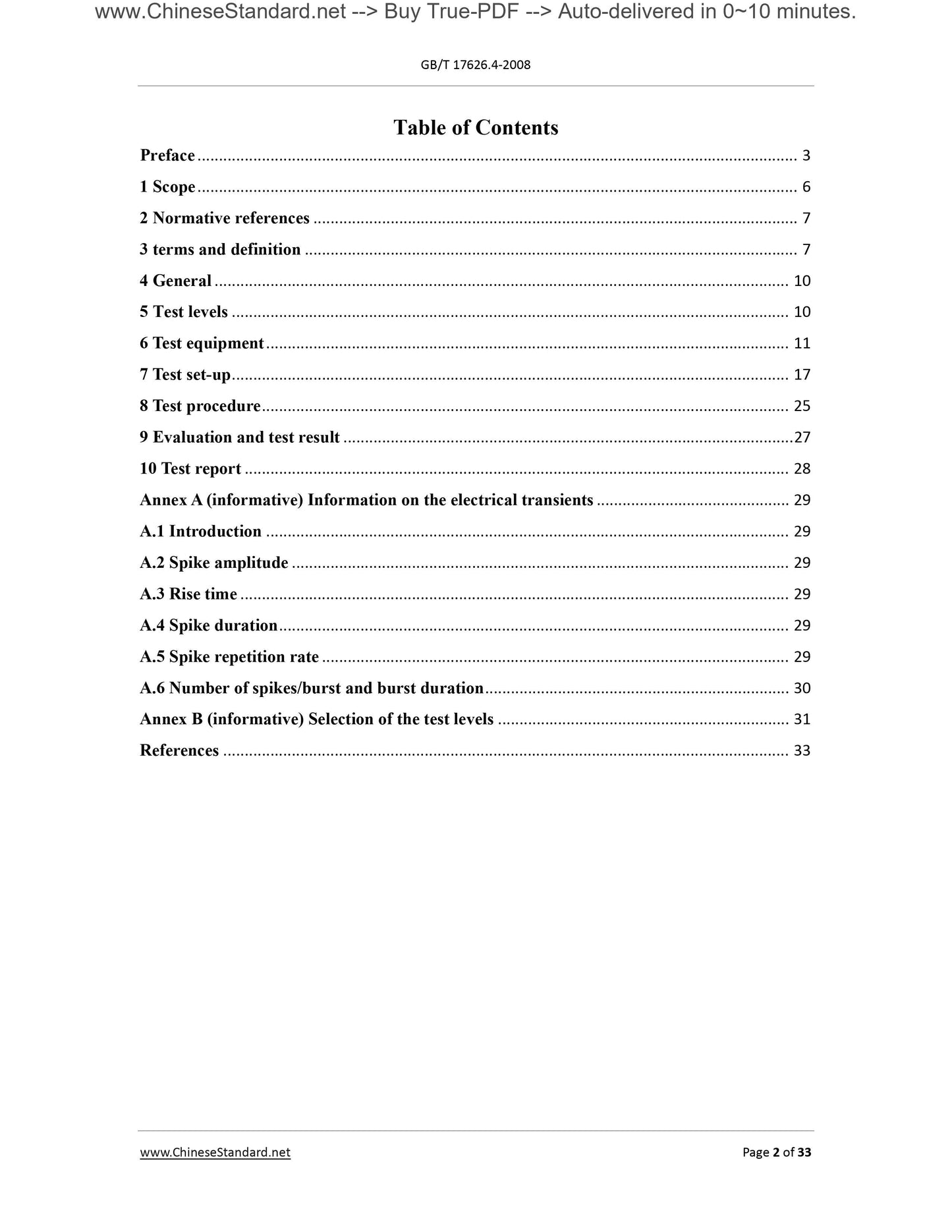
Contents
Foreword Ⅲ
1 Scope 1
2 Normative references 1
3 Terms and definitions 1
4 Overview 3
5 Test level 3
6 Test equipment 4
7 Test configuration 8
8 Test procedure 14
9 Evaluation of test results 16
10 Test report 16
Appendix A (informative appendix) Information on fast electrical transients 17
A. 1 Introduction 17
A. 2 Peak amplitude 17
A. 3 Rise time 17
A. 4 Peak duration 17
A. 5 Peak repetition rate 17
A. 6 Number of spikes/bursts and burst duration 18
Appendix B (Informative Appendix) Selection of Test Level 19
Reference 20
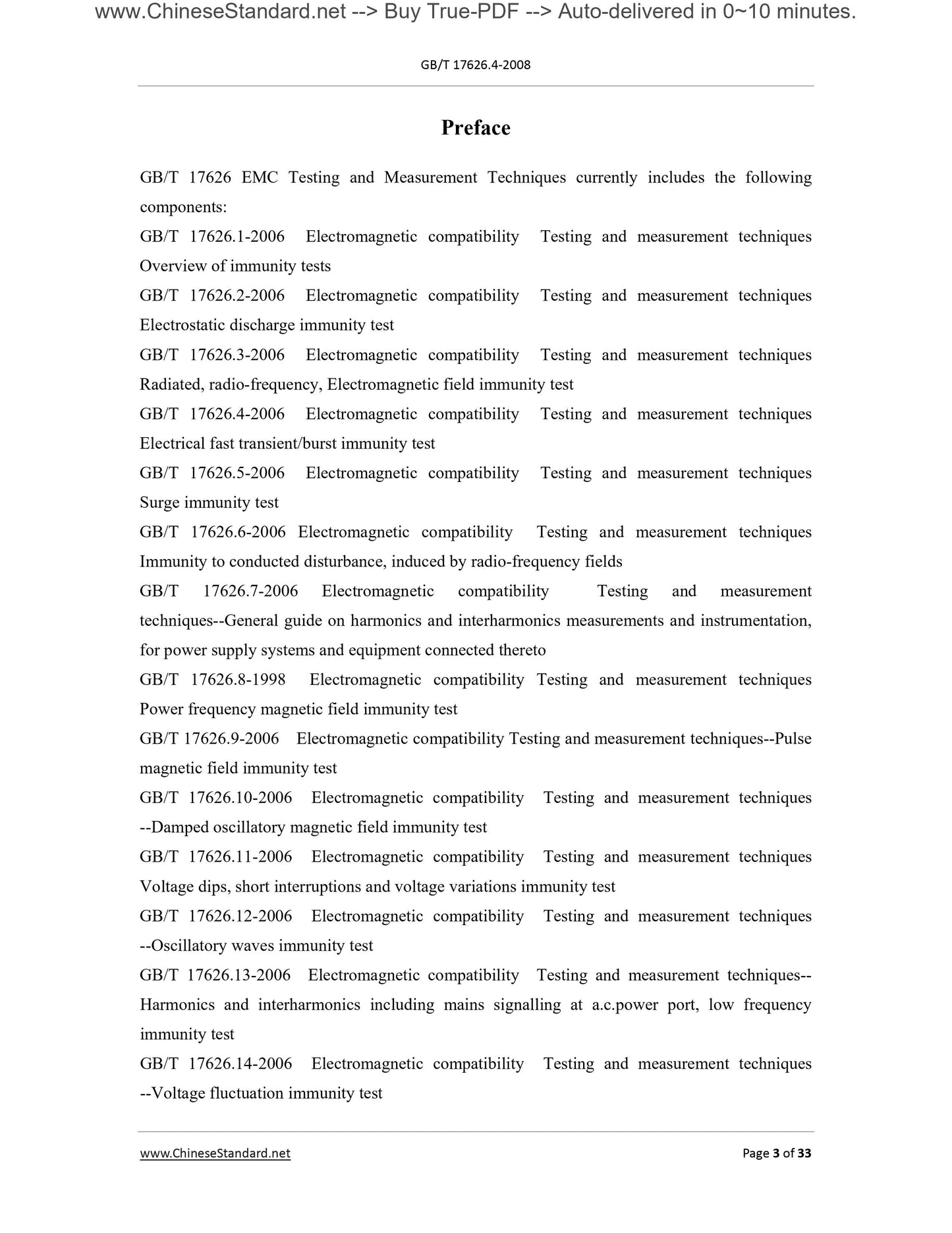
Foreword
GB/T 17626 "Electromagnetic Compatibility Test and Measurement Technology" currently includes the following parts.
GB/T 176266.1-2006 Electromagnetic compatibility test and measurement technology immunity test summary
GB/T 17626.2-2006 Electromagnetic compatibility test and measurement technology Electrostatic discharge immunity test
GB/T 17626.3-2006 Electromagnetic compatibility test and measurement technology RF electromagnetic field radiation immunity test
GB/T 17626.4-2008 Electromagnetic compatibility test and measurement technology Electrical fast transient burst immunity test
GB/T 17626.5-2008 EMC test and measurement technology surge (impact) immunity test
GB/T 17626.6-2008 Electromagnetic compatibility test and measurement technology RF field induced conducted disturbance immunity
GB/T 17626.7-2008 Electromagnetic compatibility test and measurement technology Power supply system and connected equipment Harmonic and interharmonic wave measurement and measurement instrument guide
GB/T 17626.8-2006 EMC test and measurement technology power frequency magnetic field immunity test
GB/T 17626.9-1998 Electromagnetic compatibility test and measurement technology Pulse magnetic field immunity test
GB/T 17626.10-1998 Electromagnetic compatibility test and measurement technology Damped oscillation magnetic field immunity test
GB/T 17626.11-2008 Electromagnetic compatibility test and measurement technology Voltage sag, short interruption and voltage change immunity test
GB/T 17626.12-1998 Electromagnetic compatibility test and measurement technology Oscillation wave immunity test
GB/T 17626.13-2006 Electromagnetic compatibility test and measurement technology Low-frequency immunity test of harmonics, interharmonic waves and power grid signals of AC power ports
GB/T 17626.14-2005 EMC test and measurement technology Voltage fluctuation immunity test
GB/T 17626.16-2007 Electromagnetic Compatibility Test and Measurement Technology 0Hz ~ 150kHz Common Mode Conducted Disturbance Immunity Test
GB/T 17626.17-2005 EMC test and measurement technology DC power input port ripple immunity test
GB/T 17626.27-2006 EMC test and measurement technology Three-phase voltage unbalance immunity test
GB/T 17626.28-2006 EMC test and measurement technology power frequency frequency change immunity test
GB/T 17626.29-2006 EMC test and measurement technology DC power input port voltage sag, short interruption and
Voltage change immunity test
This part is Part 4 of GB/T 17626.
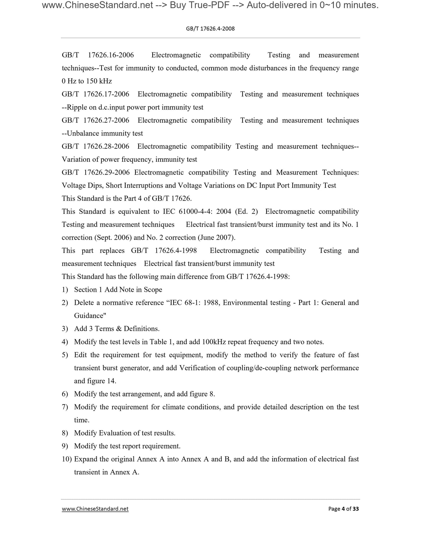
This part is equivalent to adopting the international standard IEC 61000-4-4..2004 (2nd edition) "Electromagnetic Compatibility Test and Measurement Technology
"Variable Pulse Group Immunity Test" and its Errata No. 1 (August.2006) and Errata No. 2 (June.2007).
This part replaces GB/T 17626.4-1998 "Electromagnetic Compatibility Test and Measurement Technology Electrical Fast Transient Pulse Group Immunity Test".
The main differences between this part and GB/T 17626.4-1998 are as follows.
1) Added a note to the scope of Chapter 1.
2) The reference standard IEC 68-1. 1988 "Environmental Test Part 1. General Rules and Guidelines" has been deleted.
3) Added 3 terms and definitions.
4) The test level in Table 1 has been modified to add a repetition rate of 100 kHz and two notes.
5) The requirements for test equipment have been modified, the method for verifying the characteristics of the fast transient burst generator has been modified, and the coupling/decoupling has been added.
Coupling network performance verification content, add Figure 14.
6) The test configuration was modified and Figure 8 was added.
7) Modified the requirements for climatic conditions and described the test time in detail.
8) Modified the evaluation method of the test results.
9) Modified the test report requirements.
10) Expand the original Appendix A to Appendix A and Appendix B, and add Appendix A information about fast electrical transients.
Appendix A and Appendix B of this section are informative appendices.
This part is proposed and managed by the National Electromagnetic Compatibility Standardization Technical Committee (SAC/TC246).
This section is responsible for drafting units. Shanghai Industrial Automation Instrumentation Institute, State Grid Wuhan High Voltage Research Institute.
The main drafters of this section. Wang Ying, Yang Yan, Chen Nan, Wan Baoquan, Weng Haifeng, Hong Jiye.
The release of this part instead of the previous versions of the standard is.
--- GB 13926.4-1992;
--- GB/T 17626.4-1998.
Electromagnetic compatibility test and measurement technology
Immunity test of electrical fast transient pulse group
1 Scope
This part of GB/T 17626 relates to the immunity requirements and test methods of electrical and electronic equipment for repetitive electrical fast transients. In addition,
It also stipulates the range of test grades and determines the test procedures.
The purpose of this section is to evaluate the power supply ports, signal, control and ground ports of electrical and electronic equipment that are subject to rapid electrical transients.
(Pulse group) The performance during interference determines a common reproducible evaluation basis. The test methods specified in this section describe an evaluation
A consistent method for the immunity of a prepared or system to a defined phenomenon.
Note. This part is part of the basic standards of electromagnetic compatibility of the National Electromagnetic Compatibility Standardization Technical Committee. The professional standardization technical committee is responsible for determining this
Whether the standard part of the immunity test is applicable. If applicable, the professional standardization technical committee is responsible for determining the appropriate test level and performance criteria. negative
The standardization technical committee responsible for this part is willing to cooperate with the professional standardization technical committee in the evaluation of the special immunity test values of their products.
This section specifies the following items.
--- Test voltage waveform;
--- The scope of the test level;
--- Test equipment;
--- Verification procedure of test equipment;
--- Test configuration;
--- Test procedures.
This section gives technical specifications for laboratory tests and post-installation tests.
2 Normative references
The clauses in the following documents become the clauses of this part by quoting this part of GB/T 17626. All quotes with dates
Documents, all subsequent amendments or revisions do not apply to this section, however, encourage parties to reach an agreement under this section to study whether
The latest version of these files can be used. For the cited documents without date, the latest version applies to this section.
GB/T 4365-2003 Electrotechnical term Electromagnetic compatibility (IEC 60050 (161)..1990, IDT)
IEC 60050-300..2001 International Electrotechnical Vocabulary Electrical and Electronic Measuring and Measuring Instruments Part 311. Related to Measurement
General terms; Part 312. General terms related to electrical measurement; Part 313. Types of electrical measuring instruments; Part 314. Root
Specific terms based on instrument type
3 Terms and definitions
GB/T 4365 established and the following terms and definitions apply to this part of GB/T 17626.
Note. In the following definitions, there are several most relevant terms and definitions from GB/T 4365.
3.1
A limited number of clearly identifiable pulse sequences or oscillations of limited duration.
3.2
In accordance with the relevant standards, a series of operations to establish the relationship between the indicated value and the measurement result under the prescribed conditions.
GB/T 17626.4-2008/IEC 61000-4-4..2004
[IEC 60050 (311). 311-001-09 as defined in.2001]
Note 1. The term is based on the "uncertainty" method.
Note 2. In principle, the relationship between the indication and the measurement result can be represented by a calibration chart.
3.3
The interaction between the lines transfers energy from one line to another.
3.4
Simultaneously couple all wires to the ground reference plane.
3.5
Without any electrical connection to the line under test, the disturbance signal is coupled to the line under test in a common mode with a specified size and
A feature of equipment.
3.6
A circuit used to transfer energy from one line to another.
3.7
It is used to prevent the electrical fast transient voltage applied to the equipment under test from affecting the circuits of other devices, equipment and systems that are not tested.
3.8
The undesirable deviation of the working performance of the device, equipment or system from the normal performance.
Note. The term "reduced" can be used for temporary or permanent failure.
[2.1 in GB/T 4365-2003]
3.9
Electrical fast transient burst.
3.10
The equipment or system can work normally in its electromagnetic environment and does not constitute unbearable electromagnetic disturbance to anything in the environment
ability.
[2.1 in GB/T 4365-2003]
3.11
The device under test.
3.12
A conductive plane whose potential is used as a common reference potential.
[2.4 in GB/T 4365-2003]
3.13
The ability of a device, equipment or system to face electromagnetic disturbances without reducing performance.
[2.1 in GB/T 4365-2003]
3.14
Special interface between the equipment under test and the external electromagnetic environment.
3.15
The time it takes for the pulse instantaneous value to rise from 10% to 90% of the pulse amplitude for the first time.
[2.2 in GB/T 4365-2003]
3.16
The change time of a physical quantity or physical phenomenon that changes between two adjacent stable states is less than the time scale of interest.
[2.2 in GB/T 4365-2003]
3.17
Used to check test equipment systems (for example, test signal generators and interconnecting cables) to verify that the test system is functionally compliant with Chapter 6 regulations
A series of operations carried out in accordance with the established specifications.
Note 1. The calibration method may be different from the calibration method.
Note 2. These two items 6.1.2 and 6.2.2 are a guide for ensuring the normal operation of the test signal generator, while the other clauses are used to establish the test configuration
Apply the expected waveform to the device under test.
Note 3. For basic electromagnetic compatibility standards, this definition is different from the definition in IEC 311-13.
4 Overview
Repetitive fast transient test is a kind of coupling a pulse group composed of many fast transient pulses to the power supply terminal of electrical and electronic equipment
Port, control port, signal port and ground port. The main points of the test are the high amplitude of the transient, short rise time, high repetition rate and low
energy.
The purpose of this test is to verify that electrical and electronic equipment is subjected to transient processes such as switching (switching off inductive loads, relay contact bounces, etc.)
The immunity of various types of transient disturbances.
5 Test level
Table 1 lists the test levels that should be used first when conducting electrical fast transient tests on the power, ground, signal and control ports of the equipment.
Table 1 Test grade
6 Test equipment
The verification procedures of 6.1.2 and 6.2.2 are used as a guide to ensure the correct operation of the test configuration consisting of the test generator, coupling/decoupling network, etc.
Set so that the expected waveform is correctly applied to the device under test.
6.1 Burst generator
The circuit diagram of the generator is given in Figure 1. Through the selected circuit components Cc, Rs, Rm and Cd, the generator is opened and connected
A fast transient is generated under the condition of 50Ω resistive load. The effective output impedance of the signal generator should be 50Ω.
6.1.1 Performance characteristics of fast transient burst generator
The characteristics of the fast transient burst generator are as follows.
--- Output voltage range of at least 0.25 kV to 4 kV at a load of 1000 Ω;
-The output voltage range of at least 50Ω load is from 0.125kV to 2kV.
The generator should be able to work under short circuit conditions.
6.1.2 Verification of the characteristics of fast transient burst generator
In order to establish a common reference for all generators, the characteristics of the test generator should be verified. Therefore, the following procedure should be adopted.
The output of the test generator is connected to a 50Ω and 1000Ω coaxial terminal, and an oscilloscope is used to monitor the voltage. measuring equipment
The -3dB bandwidth of the test load impedance should be at least 400MHz. For a test load of 1000Ω, the impedance may be a composite
GB/T 17626.4-2008/IEC 61000-4-4..2004
The internet. The pulse rise time, duration and repetition frequency, pulse group duration and pulse group period in a pulse group should be monito...
Share