Skip to product information
1 of 4

www.ChineseStandard.us -- Field Test Asia Pte. Ltd.

GB/T 17213.18-2015 English PDF (GB/T17213.18-2015)

GB/T 17213.18-2015 English PDF (GB/T17213.18-2015)

Regular price $180.00
Regular price Sale price $180.00
Sale Sold out
Shipping calculated at checkout.
GB/T 17213.18-2015: Industrial-process control valves -- Part 9: Test procedure for response measurements form step inputs
Delivery: 9 seconds. Download (& Email) true-PDF + Invoice.
Get Quotation: Click GB/T 17213.18-2015 (Self-service in 1-minute)
Historical versions (Master-website): GB/T 17213.18-2015
Preview True-PDF (Reload/Scroll-down if blank)

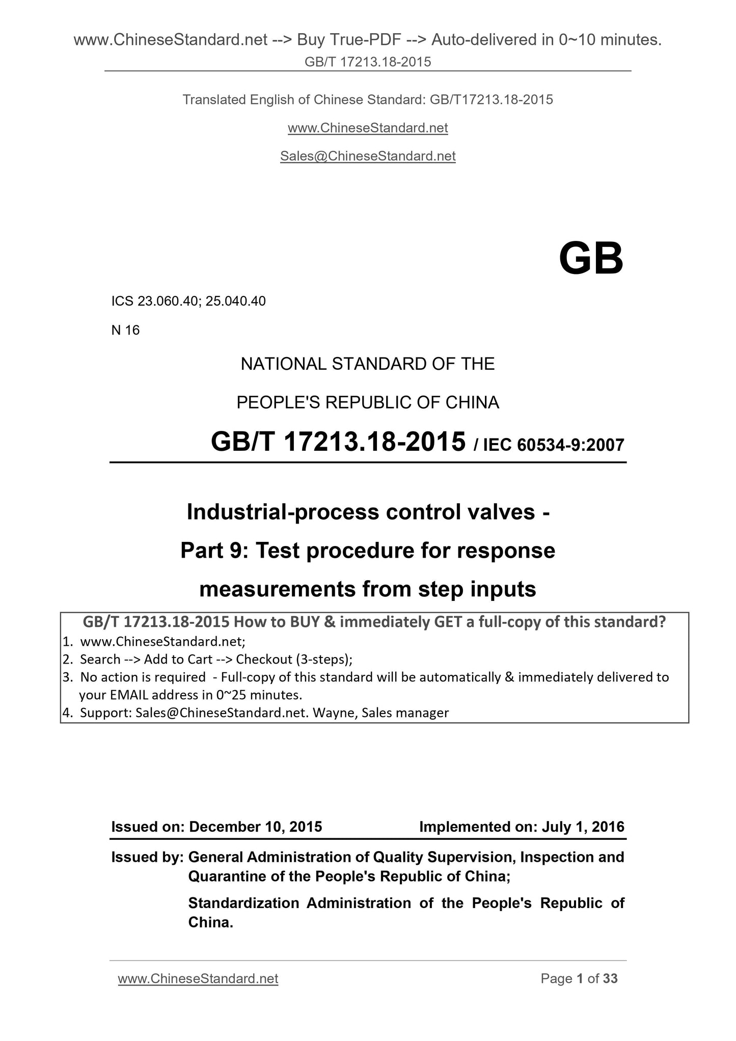
GB/T 17213.18-2015
GB
ICS 23.060.40; 25.040.40
N 16
NATIONAL STANDARD OF THE
PEOPLE'S REPUBLIC OF CHINA
GB/T 17213.18-2015 / IEC 60534-9.2007
Industrial-process control valves -
Part 9. Test procedure for response
measurements from step inputs
工业过程控制阀
(IEC 60534-9.2007, IDT)
ISSUED ON. DECEMBER 10, 2015
IMPLEMENTED ON. JULY 1, 2016
Issued by. General Administration of Quality Supervision, Inspection and
Quarantine of the People's Republic of China;
Standardization Administration of the People's Republic of
China.
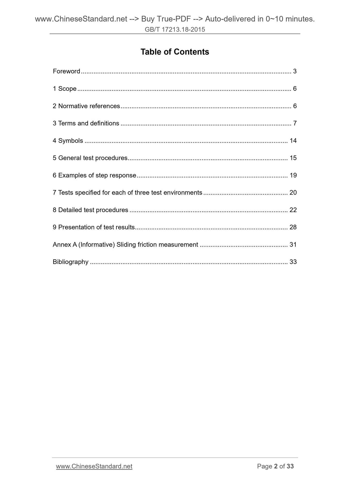
Table of Contents
Foreword ... 3 
1 Scope ... 6 
2 Normative references ... 6 
3 Terms and definitions ... 7 
4 Symbols ... 14 
5 General test procedures ... 15 
6 Examples of step response ... 19 
7 Tests specified for each of three test environments ... 20 
8 Detailed test procedures ... 22 
9 Presentation of test results ... 28 
Annex A (Informative) Sliding friction measurement ... 31 
Bibliography ... 33 
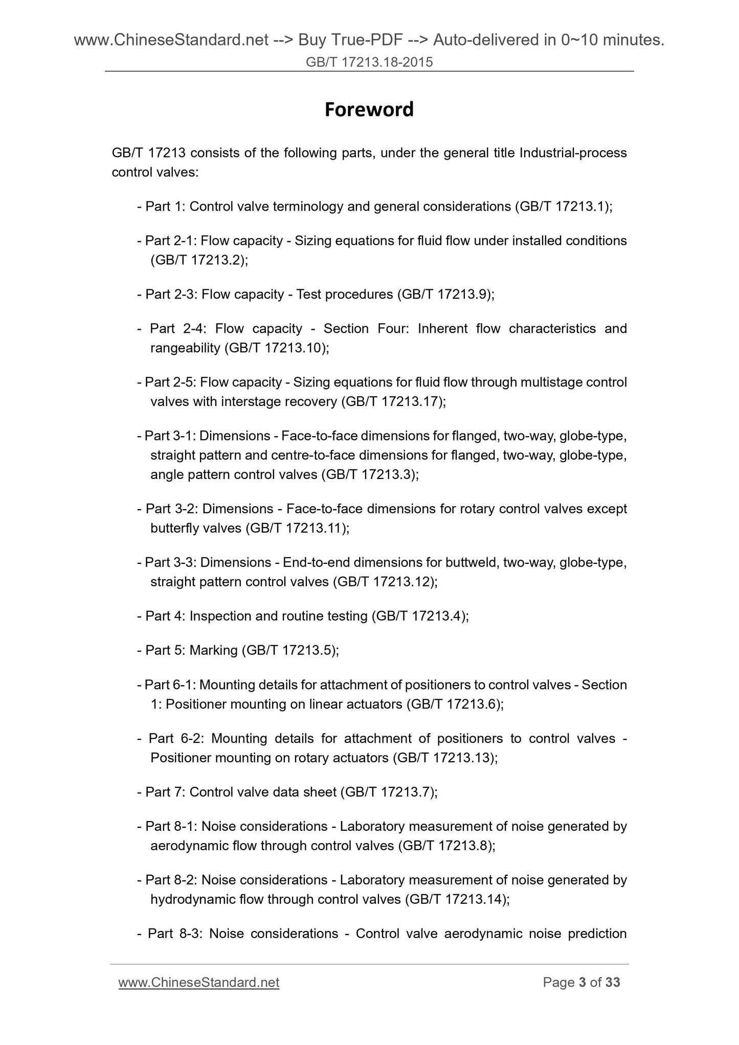
Foreword 
GB/T 17213 consists of the following parts, under the general title Industrial-process
control valves.
- Part 1. Control valve terminology and general considerations (GB/T 17213.1);
- Part 2-1. Flow capacity - Sizing equations for fluid flow under installed conditions
(GB/T 17213.2);
- Part 2-3. Flow capacity - Test procedures (GB/T 17213.9);
- Part 2-4. Flow capacity - Section Four. Inherent flow characteristics and
rangeability (GB/T 17213.10);
- Part 2-5. Flow capacity - Sizing equations for fluid flow through multistage control
valves with interstage recovery (GB/T 17213.17);
- Part 3-1. Dimensions - Face-to-face dimensions for flanged, two-way, globe-type,
straight pattern and centre-to-face dimensions for flanged, two-way, globe-type,
angle pattern control valves (GB/T 17213.3);
- Part 3-2. Dimensions - Face-to-face dimensions for rotary control valves except
butterfly valves (GB/T 17213.11);
- Part 3-3. Dimensions - End-to-end dimensions for buttweld, two-way, globe-type,
straight pattern control valves (GB/T 17213.12);
- Part 4. Inspection and routine testing (GB/T 17213.4);
- Part 5. Marking (GB/T 17213.5);
- Part 6-1. Mounting details for attachment of positioners to control valves - Section
1. Positioner mounting on linear actuators (GB/T 17213.6);
- Part 6-2. Mounting details for attachment of positioners to control valves -
Positioner mounting on rotary actuators (GB/T 17213.13);
- Part 7. Control valve data sheet (GB/T 17213.7);
- Part 8-1. Noise considerations - Laboratory measurement of noise generated by
aerodynamic flow through control valves (GB/T 17213.8);
- Part 8-2. Noise considerations - Laboratory measurement of noise generated by
hydrodynamic flow through control valves (GB/T 17213.14);
- Part 8-3. Noise considerations - Control valve aerodynamic noise prediction
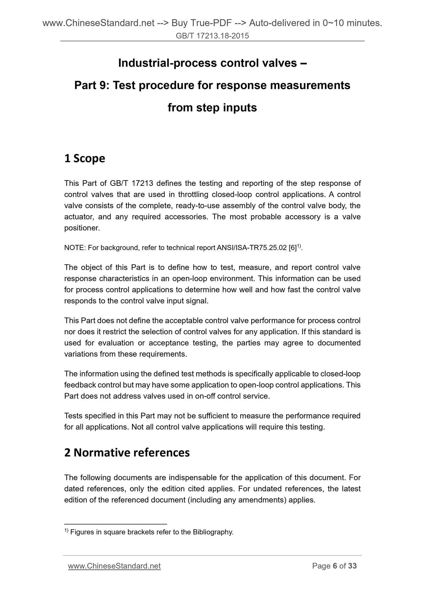
Industrial-process control valves –
Part 9. Test procedure for response measurements
from step inputs
1 Scope 
This Part of GB/T 17213 defines the testing and reporting of the step response of
control valves that are used in throttling closed-loop control applications. A control
valve consists of the complete, ready-to-use assembly of the control valve body, the
actuator, and any required accessories. The most probable accessory is a valve
positioner.
NOTE. For background, refer to technical report ANSI/ISA-TR75.25.02 [6]1).
The object of this Part is to define how to test, measure, and report control valve
response characteristics in an open-loop environment. This information can be used
for process control applications to determine how well and how fast the control valve
responds to the control valve input signal.
This Part does not define the acceptable control valve performance for process control
nor does it restrict the selection of control valves for any application. If this standard is
used for evaluation or acceptance testing, the parties may agree to documented
variations from these requirements.
The information using the defined test methods is specifically applicable to closed-loop
feedback control but may have some application to open-loop control applications. This
Part does not address valves used in on-off control service.
Tests specified in this Part may not be sufficient to measure the performance required
for all applications. Not all control valve applications will require this testing.
2 Normative references 
The following documents are indispensable for the application of this document. For
dated references, only the edition cited applies. For undated references, the latest
edition of the referenced document (including any amendments) applies.
        
1) Figures in square brackets refer to the Bibliography.

View full details