Skip to product information
1 of 6

PayPal, credit cards. Download editable-PDF and invoice in 1 second!

GB/T 16865-2013 English PDF (GBT16865-2013)

GB/T 16865-2013 English PDF (GBT16865-2013)

Regular price $185.00 USD
Regular price Sale price $185.00 USD
Sale Sold out
Shipping calculated at checkout.
Delivery: 3 seconds. Download true-PDF + Invoice.Newer version: (Replacing this standard) GB/T 16865-2023
Get QUOTATION in 1-minute: Click GB/T 16865-2013
Historical versions: GB/T 16865-2013
Preview True-PDF (Reload/Scroll if blank)

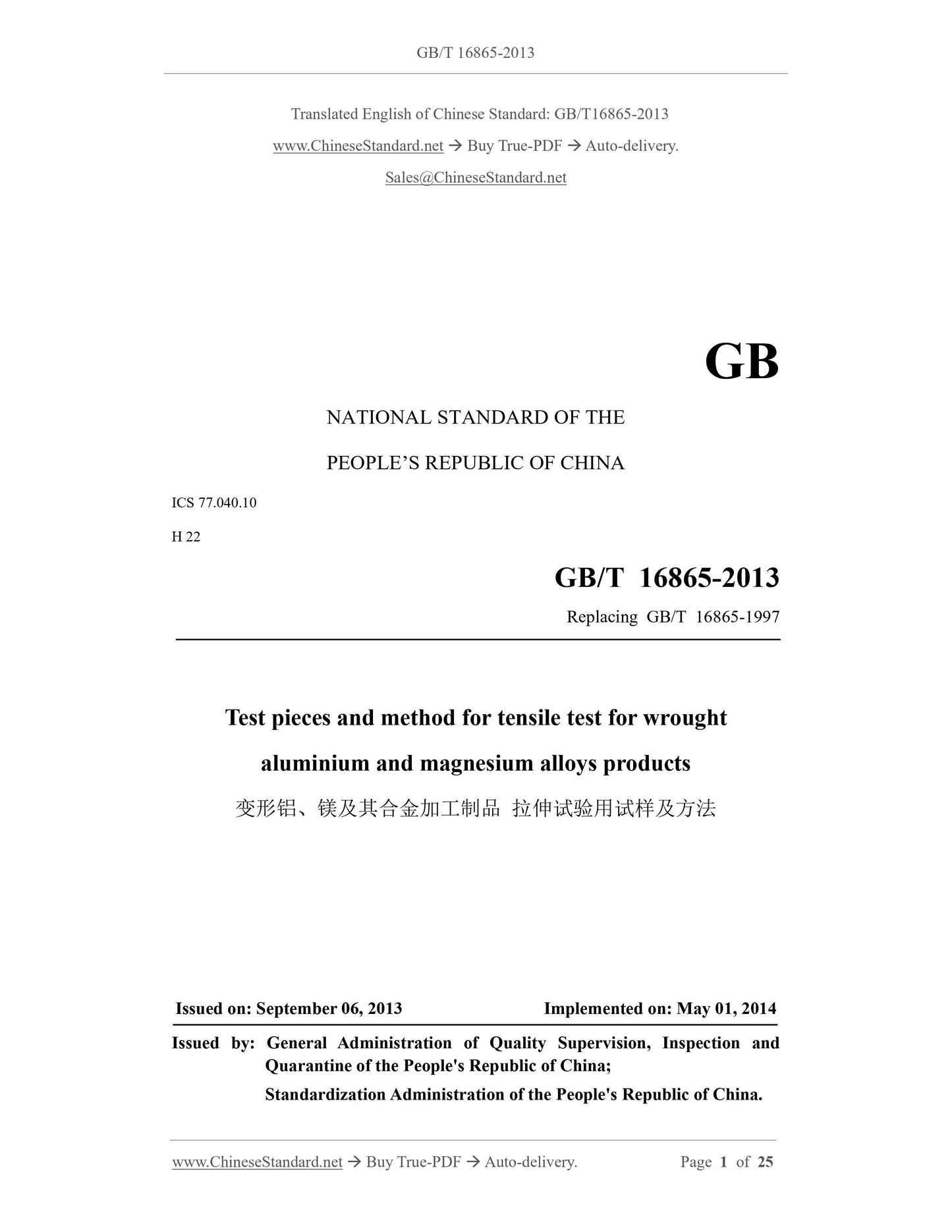
GB/T 16865-2013: Test pieces and method for tensile test for wrought aluminium and magnesium alloys products
GB/T 16865-2013
GB
NATIONAL STANDARD OF THE
PEOPLE’S REPUBLIC OF CHINA
ICS 77.040.10
H 22
Replacing GB/T 16865-1997
Test pieces and method for tensile test for wrought
aluminium and magnesium alloys products
ISSUED ON: SEPTEMBER 06, 2013
IMPLEMENTED ON: MAY 01, 2014
Issued by: General Administration of Quality Supervision, Inspection and
Quarantine of the People's Republic of China;
Standardization Administration of the People's Republic of China.
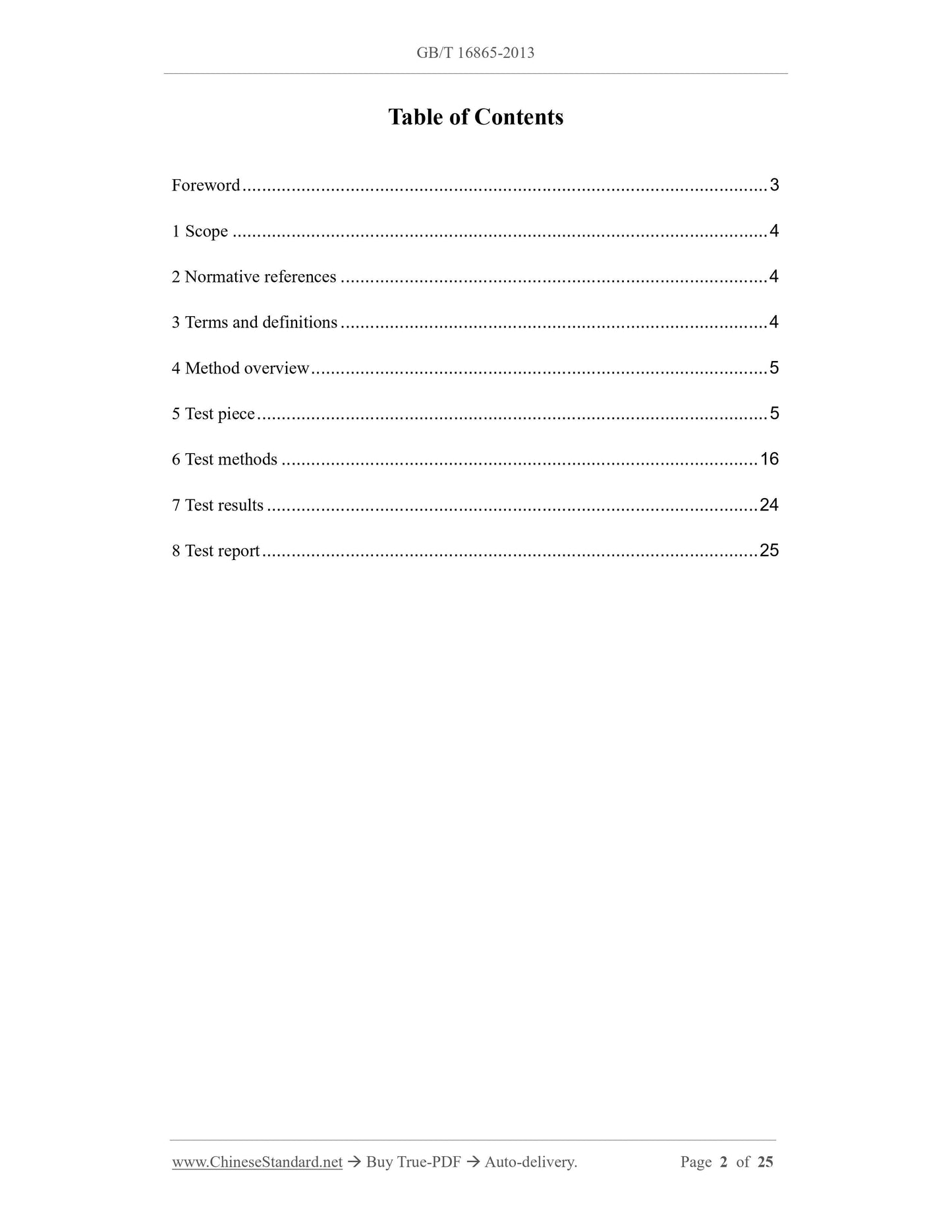
Table of Contents
Foreword ... 3 
1 Scope ... 4 
2 Normative references ... 4 
3 Terms and definitions ... 4 
4 Method overview ... 5 
5 Test piece ... 5 
6 Test methods ... 16 
7 Test results ... 24 
8 Test report ... 25 
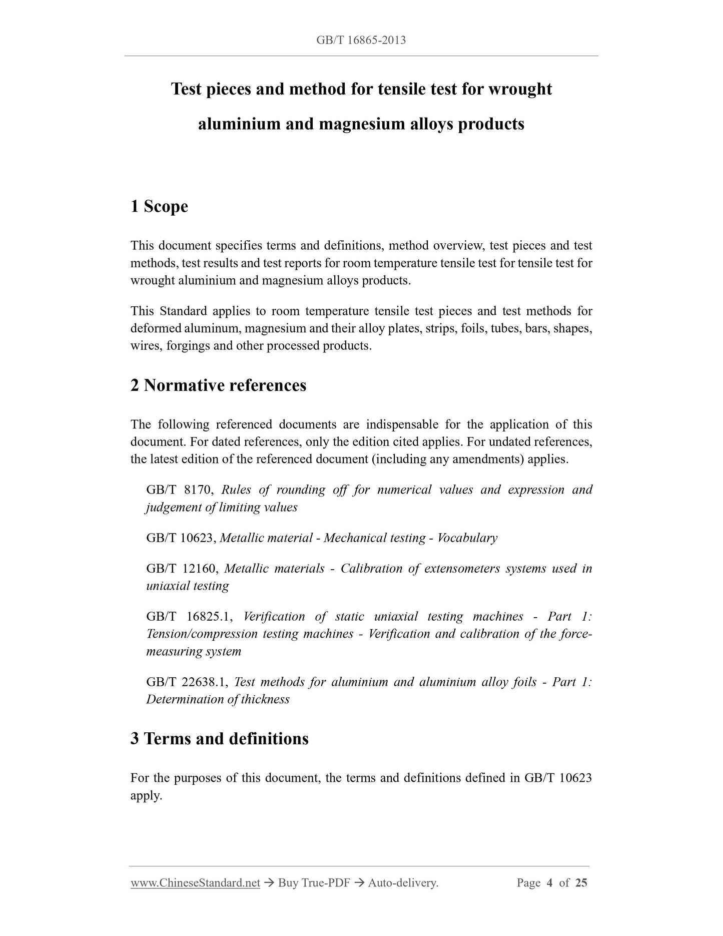
Test pieces and method for tensile test for wrought
aluminium and magnesium alloys products
1 Scope
This document specifies terms and definitions, method overview, test pieces and test
methods, test results and test reports for room temperature tensile test for tensile test for
wrought aluminium and magnesium alloys products.
This Standard applies to room temperature tensile test pieces and test methods for
deformed aluminum, magnesium and their alloy plates, strips, foils, tubes, bars, shapes,
wires, forgings and other processed products.
2 Normative references
The following referenced documents are indispensable for the application of this
document. For dated references, only the edition cited applies. For undated references,
the latest edition of the referenced document (including any amendments) applies.
GB/T 8170, Rules of rounding off for numerical values and expression and
judgement of limiting values
GB/T 10623, Metallic material - Mechanical testing - Vocabulary
GB/T 12160, Metallic materials - Calibration of extensometers systems used in
uniaxial testing
GB/T 16825.1, Verification of static uniaxial testing machines - Part 1:
Tension/compression testing machines - Verification and calibration of the force-
measuring system
GB/T 22638.1, Test methods for aluminium and aluminium alloy foils - Part 1:
Determination of thickness
3 Terms and definitions
For the purposes of this document, the terms and definitions defined in GB/T 10623
apply.
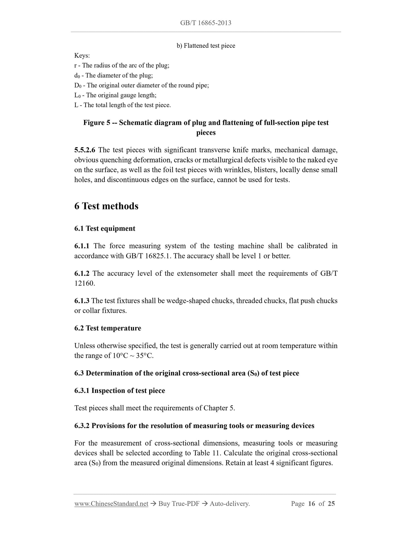
b) Flattened test piece
Keys:
r - The radius of the arc of the plug;
d0 - The diameter of the plug;
D0 - The original outer diameter of the round pipe;
L0 - The original gauge length;
L - The total length of the test piece.
Figure 5 -- Schematic diagram of plug and flattening of full-section pipe test
pieces
5.5.2.6 The test pieces with significant transverse knife marks, mechanical damage,
obvious quenching deformation, cracks or metallurgical defects visible to the naked eye
on the surface, as well as the foil test pieces with wrinkles, blisters, locally dense small
holes, and discontinuous edges on the surface, cannot be used for tests.
6 Test methods
6.1 Test equipment
6.1.1 The force measuring system of the testing machine shall be calibrated in
accordance with GB/T 16825.1. The accuracy shall be level 1 or better.
6.1.2 The accuracy level of the extensometer shall meet the requirements of GB/T
12160.
6.1.3 The test fixtures shall be wedge-shaped chucks, threaded chucks, flat push chucks
or collar fixtures.
6.2 Test temperature
Unless otherwise specified, the test is generally carried out at room temperature within
the range of 10°C ~ 35°C.
6.3 Determination of the original cross-sectional area (S0) of test piece
6.3.1 Inspection of test piece
Test pieces shall meet the requirements of Chapter 5.
6.3.2 Provisions for the resolution of measuring tools or measuring devices
For the measurement of cross-sectional dimensions, measuring tools or measuring
devices shall be selected according to Table 11. Calculate the original cross-sectional
area (S0) from the measured original dimensions. Retain at least 4 significant figures.
S0 - The original cross-sectional area of the test piece, in square millimeters (mm2);
m - The mass of the test piece, in grams (g). The measurement accuracy is 0.5%;
ρ - The density of test piece material, in grams per cubic centimeter (g/cm3). Take three
significant figures;
L - The total length of the test piece, in millimeters (mm). The measurement accuracy
is 0.1mm.
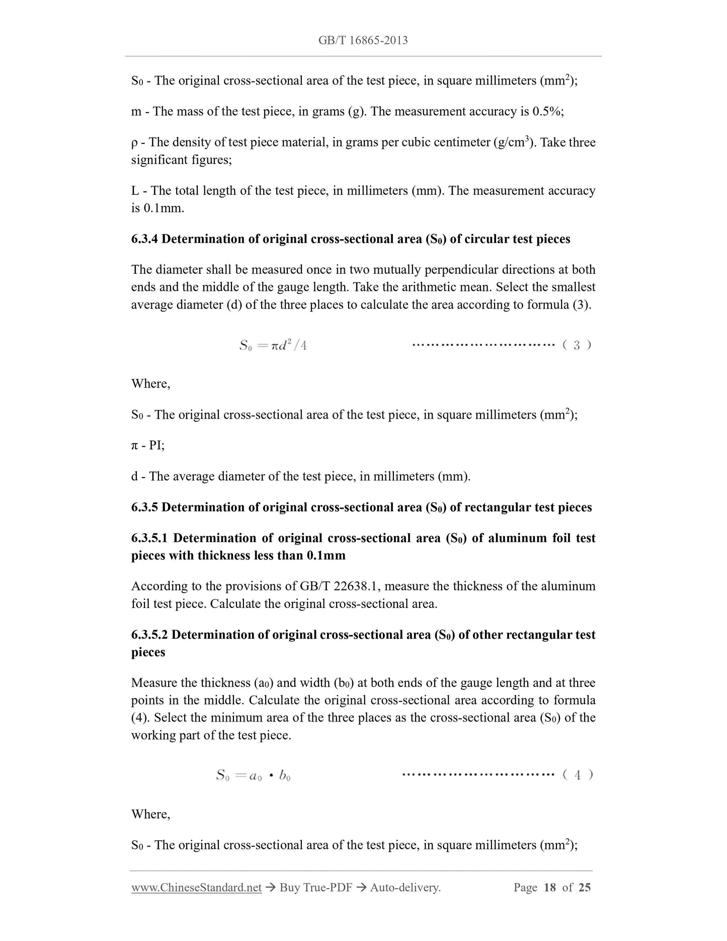
6.3.4 Determination of original cross-sectional area (S0) of circular test pieces
The diameter shall be measured once in two mutually perpendicular directions at both
ends and the middle of the gauge length. Take the arithmetic mean. Select the smallest
average diameter (d) of the three places to calculate the area according to formula (3).
Where,
S0 - The original cross-sectional area of the test piece, in square millimeters (mm2);
π - PI;
d - The average diameter of the test piece, in millimeters (mm).
6.3.5 Determination of original cross-sectional area (S0) of rectangular test pieces
6.3.5.1 Determination of original cross-sectional area (S0) of aluminum foil test
pieces with thickness less than 0.1mm
According to the provisions of GB/T 22638.1, measure the thickness of the aluminum
foil test piece. Calculate the original cross-sectional area.
6.3.5.2 Determination of original cross-sectional area (S0) of other rectangular test
pieces
Measure the thickness (a0) and width (b0) at both ends of the gauge length and at three
points in the middle. Calculate the original cross-sectional area according to formula
(4). Select the minimum area of the three places as the cross-sectional area (S0) of the
working part of the test piece.
Where,
S0 - The original cross-sectional area of the test piece, in square millimeters (mm2);
6.4.2 For proportional test pieces, the calculated value of the original gauge length shall
be rounded to the nearest multiple of 5. The median value is rounded to the larger side.
6.4.3 The original gauge length shall be marked to within ±1%.
6.5 Fixture selection
Select the appropriate fixture in 6.3 according to the test piece specification. Install on
a testing machine that meets the requirements of 6.1.
6.6 Setting of test force zero point
After the test loading chain is assembled, before both ends of the test piece are clamped,
the zero point of the force measurement system shall be set. Once the force value zero
is set, the force measurement system cannot be changed during the test.
6.7 Clamping of test piece
Clamp the test piece on the testing machine. Make sure that the clamped test piece is
under axial tension. To obtain a straight test piece and to ensure that the test piece is
aligned with the chuck, a pretension force not exceeding 5% of the specified strength
can be applied.
6.8 Test rate
6.8.1 Rate selection
During the test, the strain rate or stress rate can be selected according to the equipment
capacity.
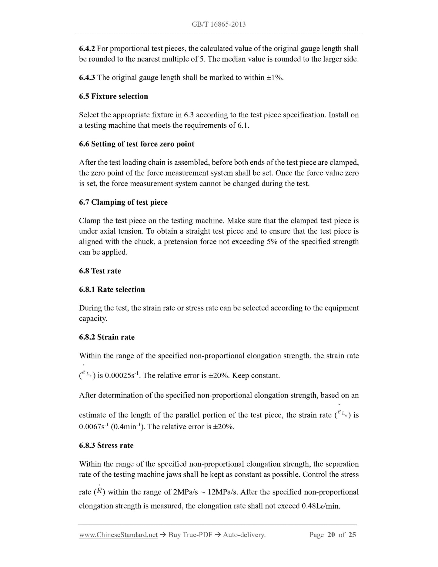
6.8.2 Strain rate
Within the range of the specified non-proportional elongation strength, the strain rate
( ) is 0.00025s-1. The relative error is ±20%. Keep constant.
After determination of the specified non-proportional elongation strength, based on an
estimate of the length of the parallel portion of the test piece, the strain rate ( ) is
0.0067s-1 (0.4min-1). The relative error is ±20%.
6.8.3 Stress rate
Within the range of the specified non-proportional elongation strength, the separation
rate of the testing machine jaws shall be kept as constant as possible. Control the stress
rate ( ) within the range of 2MPa/s ~ 12MPa/s. After the specified non-p...
View full details