GB/T 16508.3-2022 English PDF (GBT16508.3-2022)
Regular price
$1,055.00 USD
Regular price
Sale price
$1,055.00 USD
Unit price
/
per
Delivery: 3 seconds. Download true-PDF + Invoice.
Get QUOTATION in 1-minute: Click GB/T 16508.3-2022
Historical versions: GB/T 16508.3-2022
Preview True-PDF (Reload/Scroll if blank)
GB/T 16508.3-2022: Shell boilers - Part 3: Design and strength calculation
GB/T 16508.3-2022
GB
NATIONAL STANDARD OF THE
PEOPLE’S REPUBLIC OF CHINA
ICS 27.060.30
CCS J 98
Replacing GB/T 16508.3-2013
Shell boilers - Part 3: Design and strength calculation
ISSUED ON: JULY 11, 2022
IMPLEMENTED ON: FEBRUARY 01, 2023
Issued by: State Administration for Market Regulation;
Standardization Administration of the People's Republic of China.
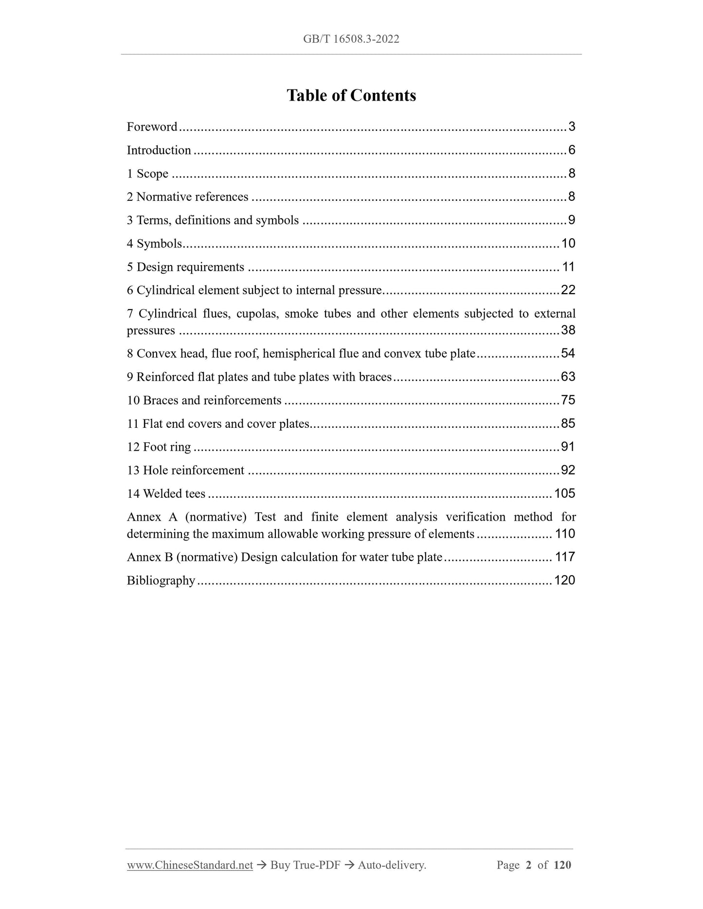
Table of Contents
Foreword ... 3
Introduction ... 6
1 Scope ... 8
2 Normative references ... 8
3 Terms, definitions and symbols ... 9
4 Symbols ... 10
5 Design requirements ... 11
6 Cylindrical element subject to internal pressure ... 22
7 Cylindrical flues, cupolas, smoke tubes and other elements subjected to external
pressures ... 38
8 Convex head, flue roof, hemispherical flue and convex tube plate ... 54
9 Reinforced flat plates and tube plates with braces ... 63
10 Braces and reinforcements ... 75
11 Flat end covers and cover plates ... 85
12 Foot ring ... 91
13 Hole reinforcement ... 92
14 Welded tees ... 105
Annex A (normative) Test and finite element analysis verification method for
determining the maximum allowable working pressure of elements ... 110
Annex B (normative) Design calculation for water tube plate ... 117
Bibliography ... 120
Shell boilers - Part 3: Design and strength calculation
1 Scope
This document specifies the design requirements and strength calculation methods for
pressure elements of shell boilers. It also specifies the test and finite element analysis
verification methods for determining the maximum allowable working pressure of
elements.
This document is applicable to the design of pressure elements of shell boilers defined
in GB/T 16508.1 [including cylindrical elements bearing internal (external) pressure,
heads, tube plates, end covers, foot rings, etc.] and braces.
2 Normative references
The following referenced documents are indispensable for the application of this
document. For dated references, only the edition cited applies. For undated references,
the latest edition of the referenced document (including any amendments) applies.
GB/T 150.3, Pressure vessels - Part 3: Design
GB/T 985.1, Recommended joint preparation for gas welding, manual metal arc
welding, gas-shield arc welding and beam welding
GB/T 985.2, Recommended joint preparation for submerged arc welding
GB/T 1576, Water quality for industrial boilers
GB/T 2900.48, Electrotechnical terminology of boilers
GB/T 9252, Method for pressure cycling test of gas cylinders
GB/T 12145, Quality criterion of water and steam for power plant and steam-
generating equipment
GB/T 16507.3, Water-tube boilers - Part 3: Structure design
GB/T 16508.1, Shell boilers - Part 1: General requirements
GB/T 16508.2, Shell boilers - Part 2: Materials
GB/T 16508.4, Shell boilers - Part 4: Fabrication, inspection and acceptance
JB/T 6734, Calculation method of strength of boiler fillet welding seam
be considered:
1) Internal or external pressure of water or steam;
2) Liquid column static pressure;
3) Working fluid flow resistance;
4) Set pressure of safety valve;
5) The following loads shall also be considered when necessary:
• Self-weight load of pressure element and built-in self-weight load;
• Gravity load of attached equipment;
• Wind, snow loads and seismic loads;
• Other forces of connecting piping (thrust and moment of the piping, etc.);
• Forces caused by temperature gradients and differences in thermal expansion;
• Impact loads when the pressure fluctuates sharply;
• Forces during transport and lifting.
b) The following loads shall be considered when designing load-bearing non-
pressure elements:
1) Permanent loads, including supporting gravity, thermal expansion thrust;
2) Transient loads, including safety valve exhaust reaction force and other short-
term forces.
5.1.3 The design shall ensure that the wall temperature of the element does not exceed
the allowable temperature of the material used. Consider factors such as the temperature
difference between the inner and outer walls of the tube on the heating surface and the
inner wall's resistance to steam oxidation.
5.1.4 The design of the boiler structure shall be convenient for installation, operation,
maintenance and cleaning inside and outside.
5.1.5 The design shall be in accordance with the relevant strength calculation formula
or stress analysis calculation formula and regulations in this document. Determine the
minimum required thickness of the pressure element.
5.1.6 Special-shaped compression elements or structures that cannot be calculated
according to the provisions of Chapters 6 to 14 and Annex B within the scope of this
document can be according to the test and finite element analysis verification methods
specified in Annex A. Determine the maximum allowable working pressure of the
element.
5.1.7 The strength calculation of boiler fillet welds shall comply with the provisions of
JB/T 6734.
5.2 Structural requirements
5.2.1 General requirements
5.2.1.1 The main pressure elements of the shell boiler include boiler shell, header,
piping, centralized descending tube, flue, backfire chamber, tube plate (head), flue roof
and foot ring, etc.
5.2.1.2 Pressure elements shall have sufficient strength. The form of the structure of the
pressure elements, the layout of the openings and welds shall avoid or reduce the
combined stress and stress concentration as far as possible.
5.2.2 Wall thickness and length of boiler shell and flue
5.2.2.1 When the inner diameter of the boiler shell is greater than 1000 mm, the wall
thickness of the boiler shell cylinder shall not be less than 6 mm. When the inner
diameter of the boiler shell is not greater than 1000 mm, the wall thickness of the boiler
shell cylinder shall not be less than 4 mm.
5.2.2.2 The wall thickness of the boiler shell cylinder and tube plate connected by
expansion joints shall not be less than 12 mm. Tubes with an outer diameter greater
than 89 mm shall not be connected by expansion joints.
5.2.2.3 The inner diameter of the flue shall not exceed 1800 mm. The flue wall thickness
meets the following requirements:
a) When the flue inner diameter is less than or equal to 1800 mm and greater than
400 mm, its wall thickness shall not be less than 8 mm and not greater than 22
mm.
b) When the flue inner diameter is less than or equal to 400 mm, the wall thickness
shall not be less than 6 mm.
5.2.2.4 For the backfire chamber of a horizontal internal combustion boiler, the wall
thickness of the cylinder shall be not less than 10 mm and not more than 35 mm.
5.2.2.5 The calculated length of the horizontal flat flue shall not exceed 2000 mm. When
the two ends of the flue are connected to the flange of the tube plate, the calculated
length of the straight flue can be enlarged to 3000 mm.
5.2.3 Safe water level
5.2.3.1 The minimum and maximum safe water levels of boilers shall be indicated on
the boiler drawings.
5.2.3.2 The minimum safe water level of the boiler during normal operation shall be
100 mm higher than the highest fire line. For a horizontal shell boiler with an inner
diameter of the shell not greater than 1500 mm, the minimum safe water level shall be
75 mm higher than the highest fire line.
5.2.3.3 When the water supply to the boiler is stopped, it will continue to run under the
rated load of the boiler. The time for the boiler water level to drop from the lowest ...