Skip to product information
1 of 7

PayPal, credit cards. Download editable-PDF and invoice in 1 second!

GB/T 15335-2019 English PDF (GB/T15335-2019)

GB/T 15335-2019 English PDF (GB/T15335-2019)

Regular price $130.00
Regular price Sale price $130.00
Sale Sold out
Shipping calculated at checkout.
GB/T 15335-2019: Determination of leakage rate and specific resistance for air duct
Delivery: 9 seconds. Download (& Email) true-PDF + Invoice.
Get Quotation: Click GB/T 15335-2019 (Self-service in 1-minute)
Historical versions (Master-website): GB/T 15335-2019
Preview True-PDF (Reload/Scroll-down if blank)

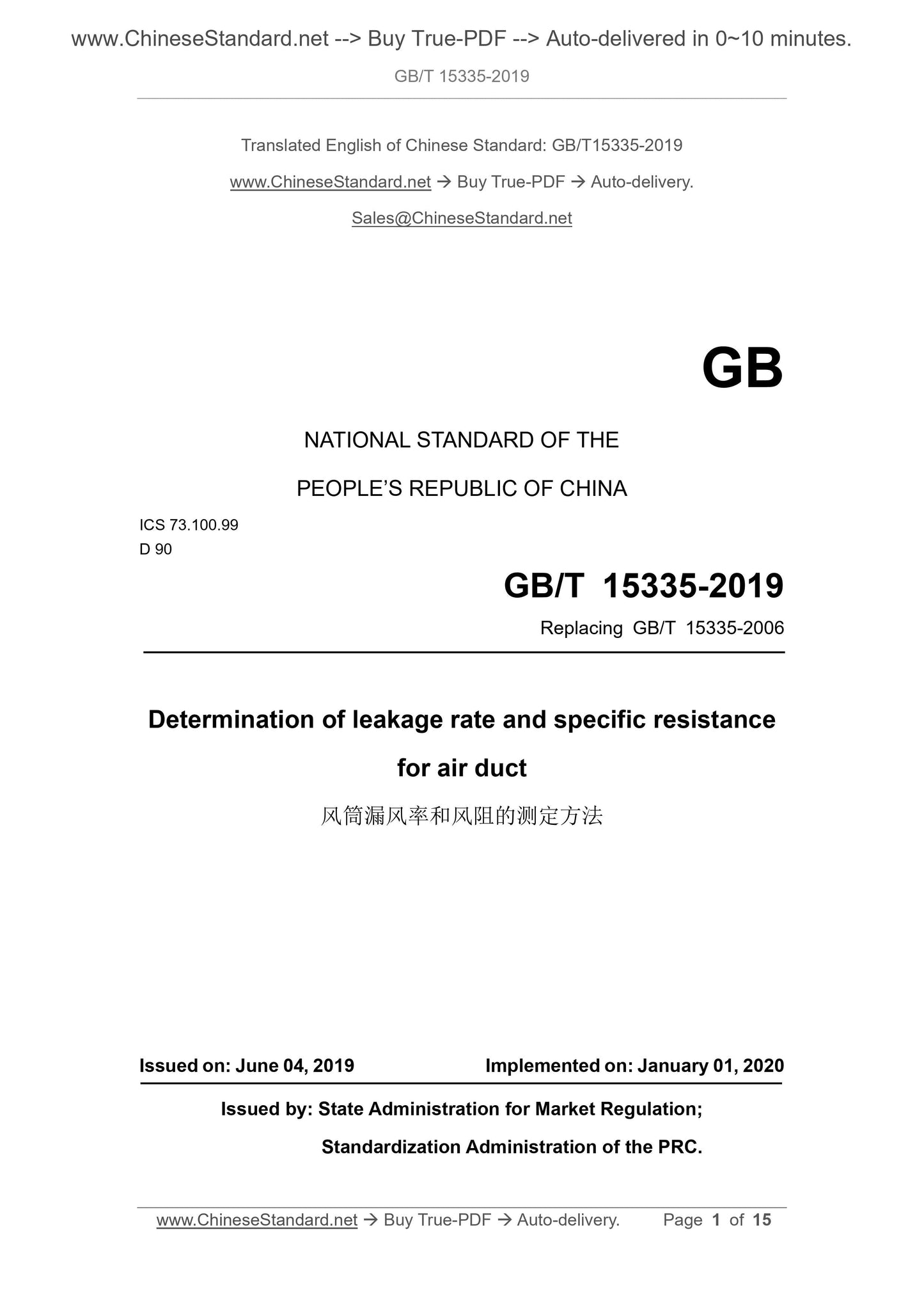
GB/T 15335-2019
NATIONAL STANDARD OF THE
PEOPLE’S REPUBLIC OF CHINA
ICS 73.100.99
D 90
Replacing GB/T 15335-2006
Determination of leakage rate and specific resistance
for air duct
ISSUED ON: JUNE 04, 2019
IMPLEMENTED ON: JANUARY 01, 2020
Issued by: State Administration for Market Regulation;
Standardization Administration of the PRC.
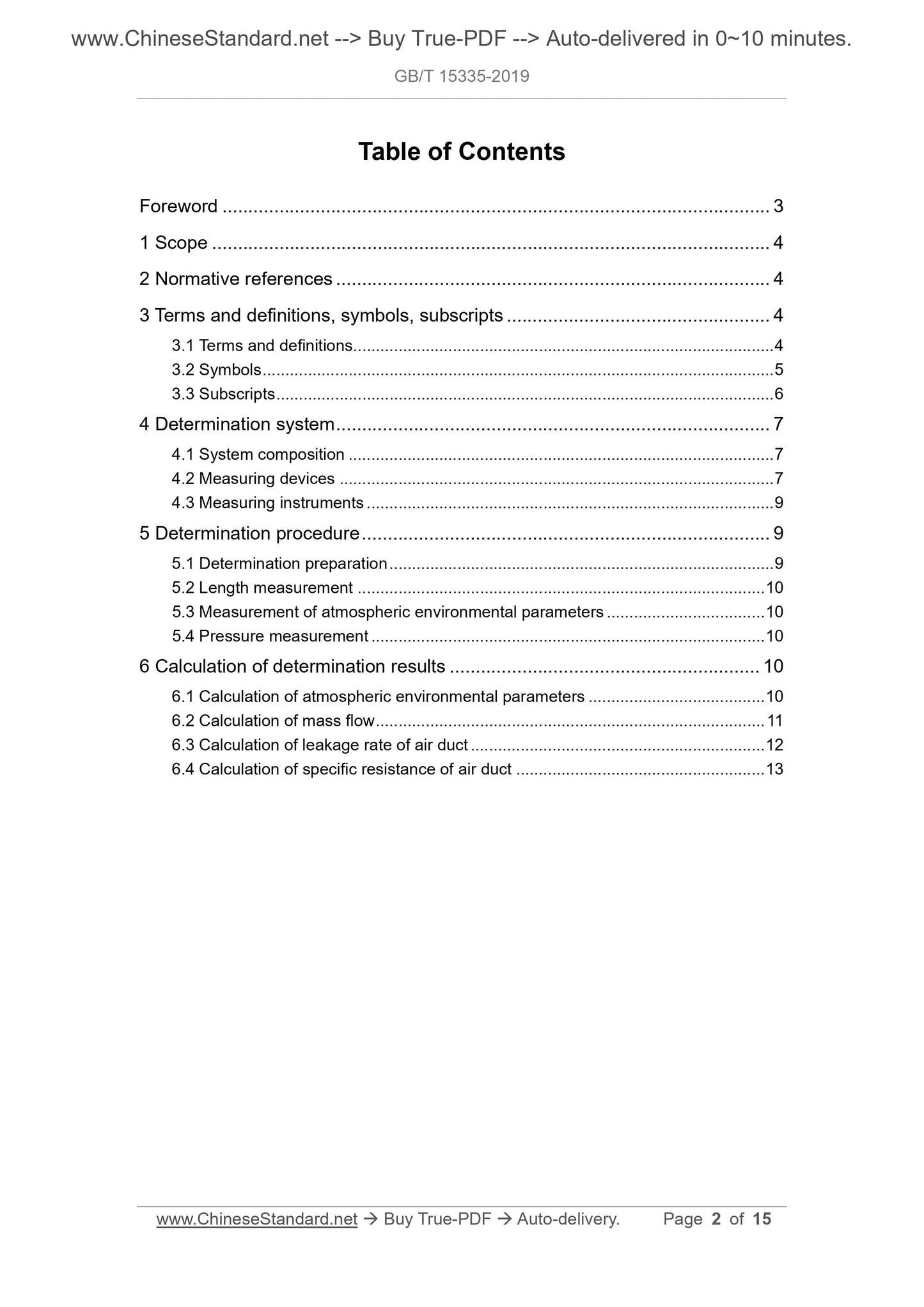
Table of Contents
Foreword ... 3 
1 Scope ... 4 
2 Normative references ... 4 
3 Terms and definitions, symbols, subscripts ... 4 
3.1 Terms and definitions ... 4 
3.2 Symbols ... 5 
3.3 Subscripts ... 6 
4 Determination system ... 7 
4.1 System composition ... 7 
4.2 Measuring devices ... 7 
4.3 Measuring instruments ... 9 
5 Determination procedure ... 9 
5.1 Determination preparation ... 9 
5.2 Length measurement ... 10 
5.3 Measurement of atmospheric environmental parameters ... 10 
5.4 Pressure measurement ... 10 
6 Calculation of determination results ... 10 
6.1 Calculation of atmospheric environmental parameters ... 10 
6.2 Calculation of mass flow ... 11 
6.3 Calculation of leakage rate of air duct ... 12 
6.4 Calculation of specific resistance of air duct ... 13 
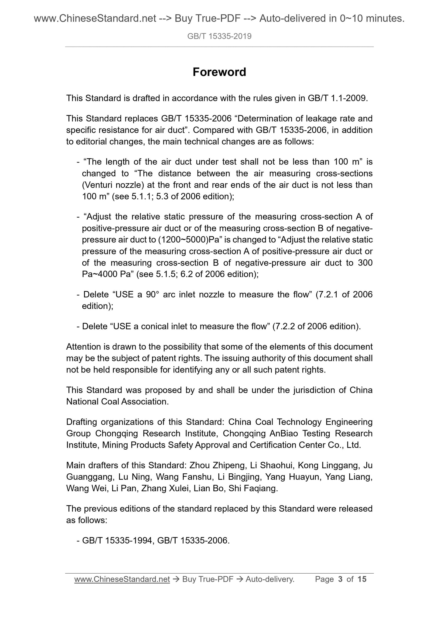
Foreword
This Standard is drafted in accordance with the rules given in GB/T 1.1-2009.
This Standard replaces GB/T 15335-2006 “Determination of leakage rate and
specific resistance for air duct”. Compared with GB/T 15335-2006, in addition
to editorial changes, the main technical changes are as follows:
- “The length of the air duct under test shall not be less than 100 m” is
changed to “The distance between the air measuring cross-sections
(Venturi nozzle) at the front and rear ends of the air duct is not less than
100 m” (see 5.1.1; 5.3 of 2006 edition);
- “Adjust the relative static pressure of the measuring cross-section A of
positive-pressure air duct or of the measuring cross-section B of negative-
pressure air duct to (1200~5000)Pa” is changed to “Adjust the relative static
pressure of the measuring cross-section A of positive-pressure air duct or
of the measuring cross-section B of negative-pressure air duct to 300
Pa~4000 Pa” (see 5.1.5; 6.2 of 2006 edition);
- Delete “USE a 90° arc inlet nozzle to measure the flow” (7.2.1 of 2006
edition);
- Delete “USE a conical inlet to measure the flow” (7.2.2 of 2006 edition).
Attention is drawn to the possibility that some of the elements of this document
may be the subject of patent rights. The issuing authority of this document shall
not be held responsible for identifying any or all such patent rights.
This Standard was proposed by and shall be under the jurisdiction of China
National Coal Association.
Drafting organizations of this Standard: China Coal Technology Engineering
Group Chongqing Research Institute, Chongqing AnBiao Testing Research
Institute, Mining Products Safety Approval and Certification Center Co., Ltd.
Main drafters of this Standard: Zhou Zhipeng, Li Shaohui, Kong Linggang, Ju
Guanggang, Lu Ning, Wang Fanshu, Li Bingjing, Yang Huayun, Yang Liang,
Wang Wei, Li Pan, Zhang Xulei, Lian Bo, Shi Faqiang.
The previous editions of the standard replaced by this Standard were released
as follows:
- GB/T 15335-1994, GB/T 15335-2006.
Determination of leakage rate and specific resistance
for air duct
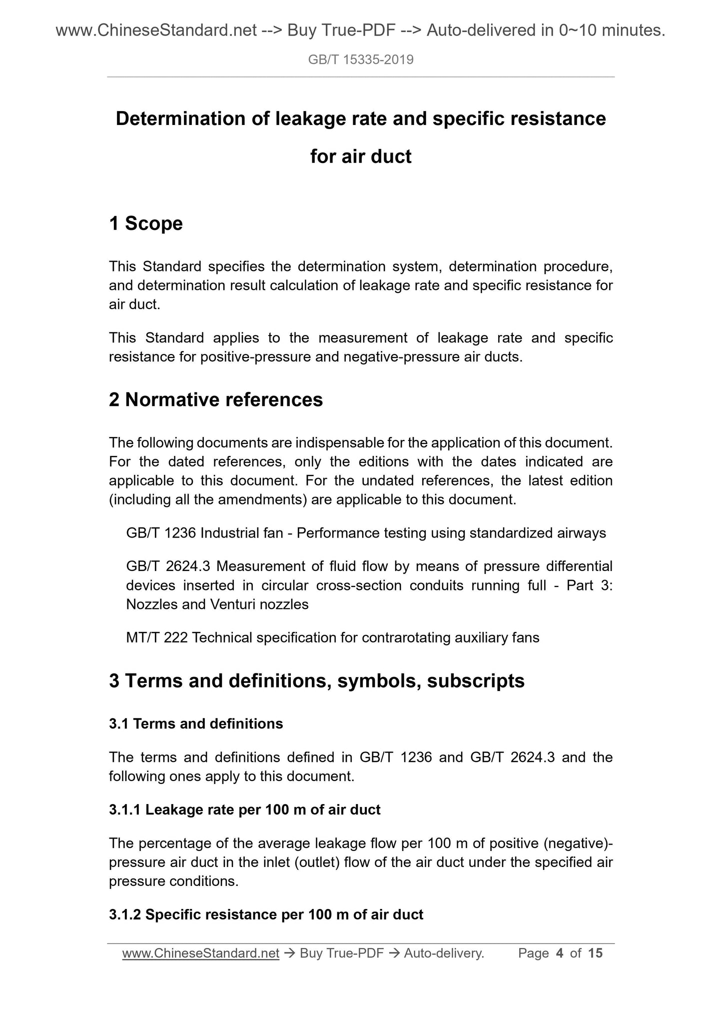
1 Scope
This Standard specifies the determination system, determination procedure,
and determination result calculation of leakage rate and specific resistance for
air duct.
This Standard applies to the measurement of leakage rate and specific
resistance for positive-pressure and negative-pressure air ducts.
2 Normative references
The following documents are indispensable for the application of this document.
For the dated references, only the editions with the dates indicated are
applicable to this document. For the undated references, the latest edition
(including all the amendments) are applicable to this document.
GB/T 1236 Industrial fan - Performance testing using standardized airways
GB/T 2624.3 Measurement of fluid flow by means of pressure differential
devices inserted in circular cross-section conduits running full - Part 3:
Nozzles and Venturi nozzles
MT/T 222 Technical specification for contrarotating auxiliary fans
3 Terms and definitions, symbols, subscripts
3.1 Terms and definitions
The terms and definitions defined in GB/T 1236 and GB/T 2624.3 and the
following ones apply to this document.
3.1.1 Leakage rate per 100 m of air duct
The percentage of the average leakage flow per 100 m of positive (negative)-
pressure air duct in the inlet (outlet) flow of the air duct under the specified air
pressure conditions.
3.1.2 Specific resistance per 100 m of air duct
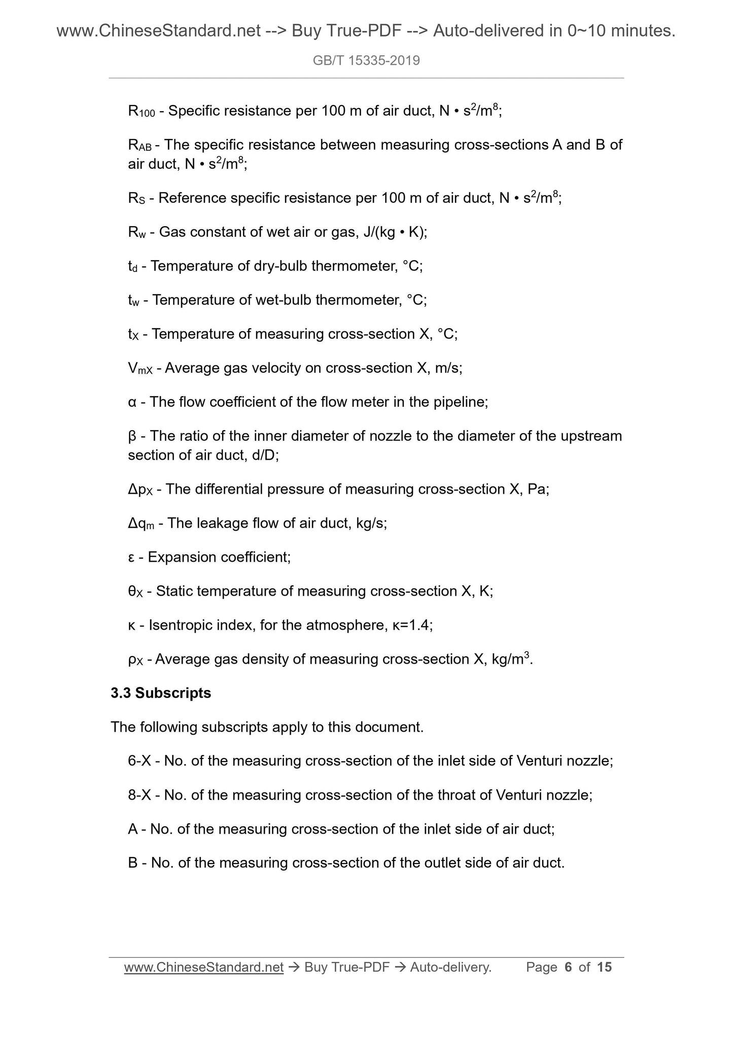
R100 - Specific resistance per 100 m of air duct, N • s2/m8;
RAB - The specific resistance between measuring cross-sections A and B of
air duct, N • s2/m8;
RS - Reference specific resistance per 100 m of air duct, N • s2/m8;
Rw - Gas constant of wet air or gas, J/(kg • K);
td - Temperature of dry-bulb thermometer, °C;
tw - Temperature of wet-bulb thermometer, °C;
tX - Temperature of measuring cross-section X, °C;
VmX - Average gas velocity on cross-section X, m/s;
α - The flow coefficient of the flow meter in the pipeline;
β - The ratio of the inner diameter of nozzle to the diameter of the upstream
section of air duct, d/D;
ΔpX - The differential pressure of measuring cross-section X, Pa;
Δqm - The leakage flow of air duct, kg/s;
ε - Expansion coefficient;
θX - Static temperature of measuring cross-section X, K;
κ - Isentropic index, for the atmosphere, κ=1.4;
ρX - Average gas density of measuring cross-section X, kg/m3.
3.3 Subscripts
The following subscripts apply to this document.
6-X - No. of the measuring cross-section of the inlet side of Venturi nozzle;
8-X - No. of the measuring cross-section of the throat of Venturi nozzle;
A - No. of the measuring cross-section of the inlet side of air duct;
B - No. of the measuring cross-section of the outlet side of air duct.
the measuring cross-section A of positive-pressure air duct or of the measuring
cross-section B of negative-pressure air duct to 300 Pa~4000 Pa.
5.2 Length measurement
5.2.1 MEASURE the distance LAB of the two measuring cross-sections A and B
of the air duct under test determined according to 4.2.4.1.
5.2.2 MEASURE the length L of the air duct under test.
5.3 Measurement of atmospheric environmental parameters
5.3.1 At the center height of the test system, MEASURE the ambient
atmospheric pressure pa.
5.3.2 MEASURE the test ambient temperature, wet-bulb temperature or relative
air humidity. MEASURE the temperature, wet-bulb temperature or relative air
humidity of each measuring cross-section.
5.4 Pressure measurement
5.4.1 INSERT the pitot tube perpendicular to the airflow direction into the two
measuring cross-sections A and B of the air duct under test determined by
4.2.4.1. Connect the pressure gauge to the static pressure port of the pitot tube
through the pressure measuring pipeline. MEASURE the relative static
pressure peA and peB at the cross-sections A and B respectively.
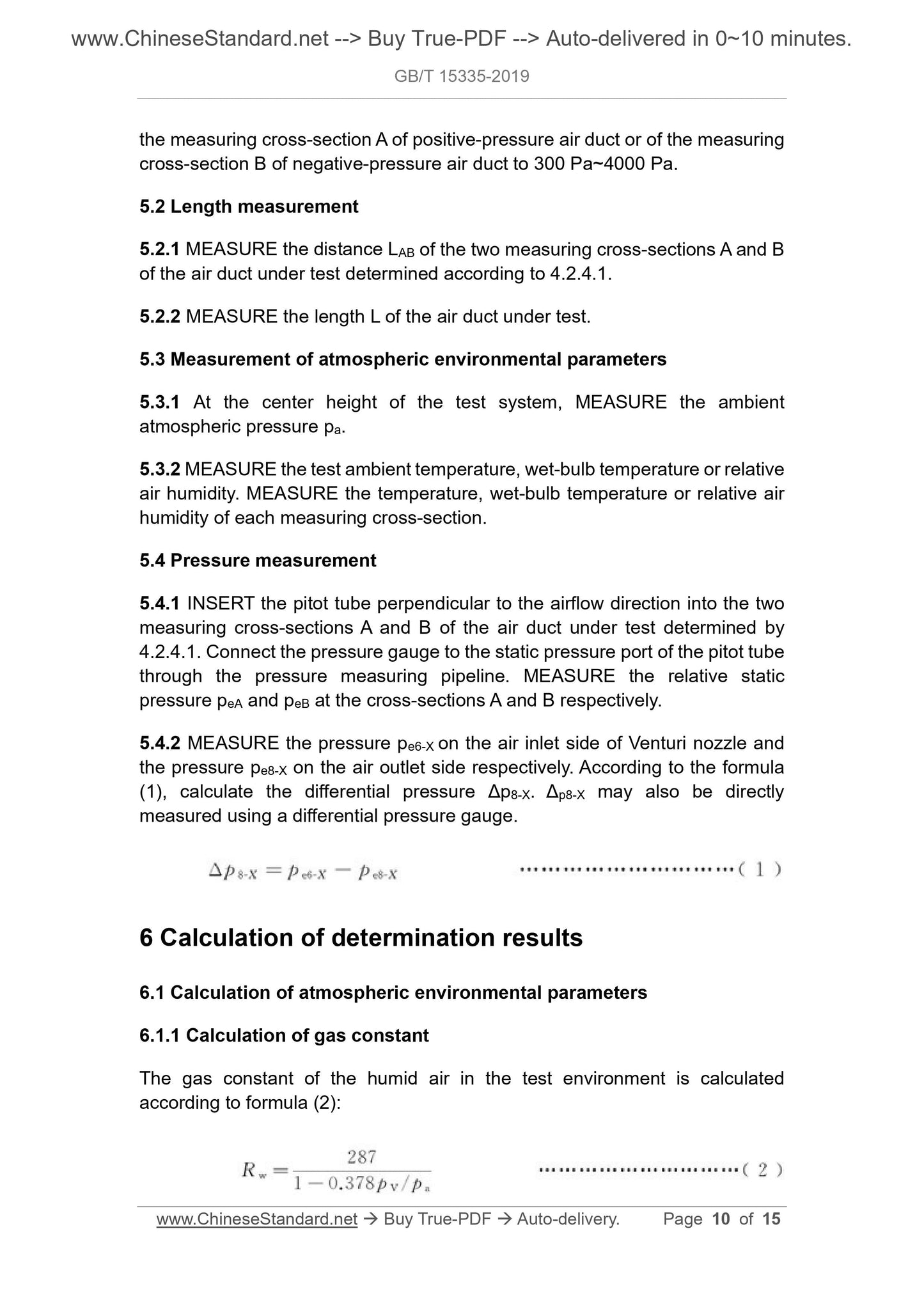
5.4.2 MEASURE the pressure pe6-X on the air inlet side of Venturi nozzle and
the pressure pe8-X on the air outlet side respectively. According to the formula
(1), calculate the differential pressure Δp8-X. Δp8-X may also be directly
measured using a differential pressure gauge.
6 Calculation of determination results
6.1 Calculation of atmospheric environmental parameters
6.1.1 Calculation of gas constant
The gas constant of the humid air in the test environment is calculated
according to formula (2):
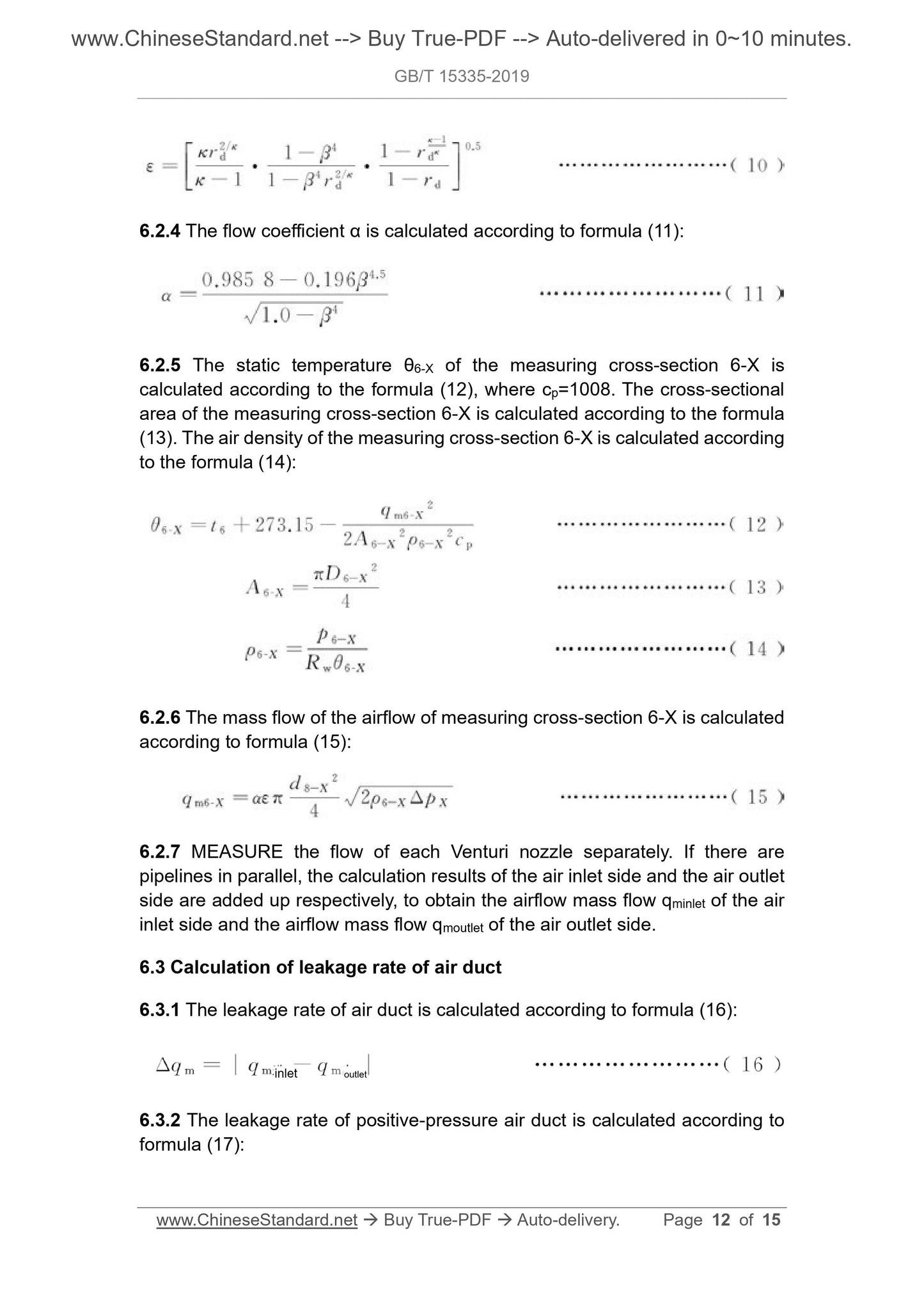
6.2.4 The flow coefficient α is calculated according to formula (11):
6.2.5 The static temperature θ6-X of the measuring cross-section 6-X is
calculated according to the formula (12), where cp=1008. The cross-sectional
area of the measuring cross-section 6-X is calculated according to the formula
(13). The air density of the measuring cross-section 6-X is calculated according
to the formula (14):
6.2.6 The mass flow of the airflow of measuring cross-section 6-X is calculated
according to formula (15):
6.2.7 MEASURE the flow of each Venturi nozzle separately. If there are
pipelines in parallel, the calculation results of the air inlet side and the air outlet
side are added up respectively, to obtain the airflow mass flow qminlet of the air
inlet side and the airflow mass flow qmoutlet of the air outlet side.
6.3 Calculation of leakage rate of air duct
6.3.1 The leakage rate of air duct is calculated according to formula (16):
6.3.2 The leakage rate of positive-pressure air duct is calculated according to
formula (17):
inlet outlet
GB/T 15335-2019
NATIONAL STANDARD OF THE
PEOPLE’S REPUBLIC OF CHINA
ICS 73.100.99
D 90
Replacing GB/T 15335-2006
Determination of leakage rate and specific resistance
for air duct
ISSUED ON: JUNE 04, 2019
IMPLEMENTED ON: JANUARY 01, 2020
Issued by: State Administration for Market Regulation;
Standardization Administration of the PRC.
Table of Contents
Foreword ... 3 
1 Scope ... 4 
2 Normative references ... 4 
3 Terms and definitions, symbols, subscripts ... 4 
3.1 Terms and definitions ... 4 
3.2 Symbols ... 5 
3.3 Subscripts ... 6 
4 Determination system ... 7 
4.1 System composition ... 7 
4.2 Measuring devices ... 7 
4.3 Measuring instruments ... 9 
5 Determination procedure ... 9 
5.1 Determination preparation ... 9 
5.2 Length measurement ... 10 
5.3 Measurement of atmospheric environmental parameters ... 10 
5.4 Pressure measurement ... 10 
6 Calculation of determination results ... 10 
6.1 Calculation of atmospheric environmental parameters ... 10 
6.2 Calculation of mass flow ... 11 
6.3 Calculation of leakage rate of air duct ... 12 
6.4 Calculation of specific resistance of air duct ... 13 
Foreword
This Standard is drafted in accordance with the rules given in GB/T 1.1-2009.
This Standard replaces GB/T 15335-2006 “Determination of leakage rate and
specific resistance for air duct”. Compared with GB/T 15335-2006, in addition
to editorial changes, the main technical changes are as follows:
- “The length of the air duct under test shall not be less than 100 m” is
changed to “The distance between the air measuring cross-sections
(Venturi nozzle) at the front and rear ends of the air duct is not less than
100 m” (see 5.1.1; 5.3 of 2006 edition);
- “Adjust the relative static pressure of the measuring cross-section A of
positive-pressure air duct or of the measuring cross-section B of negative-
pressure air duct to (1200~5000)Pa” is changed to “Adjust the relative static
pressure of the measuring cross-section A of positive-pressure air duct or
of the measuring cross-section B of negative-pressure air duct to 300
Pa~4000 Pa” (see 5.1.5; 6.2 of 2006 edition);
- Delete “USE a 90° arc inlet nozzle to measure the flow” (7.2.1 of 2006
edition);
- Delete “USE a conical inlet to measure the flow” (7.2.2 of 2006 edition).
Attention is drawn to the possibility that some of the elements of this document
may be the subject of patent rights. The issuing authority of this document shall
not be held responsible for identifying any or all such patent rights.
This Standard was proposed by and shall be under the jurisdiction of China
National Coal Association.
Drafting organizations of this Standard: China Coal Technology Engineering
Group Chongqing Research Institute, Chongqing AnBiao Testing Research
Institute, Mining Products Safety Approval and Certification Center Co., Ltd.
Main drafters of this Standard: Zhou Zhipeng, Li Shaohui, Kong Linggang, Ju
Guanggang, Lu Ning, Wang Fanshu, Li Bingjing, Yang Huayun, Yang Liang,
Wang Wei, Li Pan, Zhang Xulei, Lian Bo, Shi Faqiang.
The previous editions of the standard replaced by this Standard were released
as follows:
- GB/T 15335-1994, GB/T 15335-2006.
Determination of leakage rate and specific resistance
for air duct
1 Scope
This Standard specifies the determination system, determination procedure,
and determination result calculation of leakage rate and specific resistance for
air duct.
This Standard applies to the measurement of leakage rate and specific
resistance for positive-pressure and negative-pressure air ducts.
2 Normative references
The following documents are indispensable for the application of this document.
For the dated references, only the editions with the dates indicated are
applicable to this document. For the undated references, the latest edition
(including all the amendments) are applicable to this document.
GB/T 1236 Industrial fan - Performance testing using standardized airways
GB/T 2624.3 Measurement of fluid flow by means of pressure differential
devices inserted in circular cross-section conduits running full - Part 3:
Nozzles and Venturi nozzles
MT/T 222 Technical specification for contrarotating auxiliary fans
3 Terms and definitions, symbols, subscripts
3.1 Terms and definitions
The terms and definitions defined in GB/T 1236 and GB/T 2624.3 and the
following ones apply to this document.
3.1.1 Leakage rate per 100 m of air duct
The percentage of the average leakage flow per 100 m of positive (negative)-
pressure air duct in the inlet (outlet) flow of the air duct under the specified air
pressure conditions.
3.1.2 Specific resistance per 100 m of air duct
R100 - Specific resistance per 100 m of air duct, N • s2/m8;
RAB - The specific resistance between measuring cross-sections A and B of
air duct, N • s2/m8;
RS - Reference specific resistance per 100 m of air duct, N • s2/m8;
Rw - Gas constant of wet air or gas, J/(kg • K);
td - Temperature of dry-bulb thermometer, °C;
tw - Temperature of wet-bulb thermometer, °C;
tX - Temperature of measuring cross-section X, °C;
VmX - Average gas velocity on cross-section X, m/s;
α - The flow coefficient of the flow meter in the pipeline;...
View full details