Skip to product information
1 of 9

PayPal, credit cards. Download editable-PDF and invoice in 1 second!

GB/T 14230-2021 English PDF (GBT14230-2021)

GB/T 14230-2021 English PDF (GBT14230-2021)

Regular price $565.00 USD
Regular price Sale price $565.00 USD
Sale Sold out
Shipping calculated at checkout.
Delivery: 3 seconds. Download true-PDF + Invoice.
Get QUOTATION in 1-minute: Click GB/T 14230-2021
Historical versions: GB/T 14230-2021
Preview True-PDF (Reload/Scroll if blank)

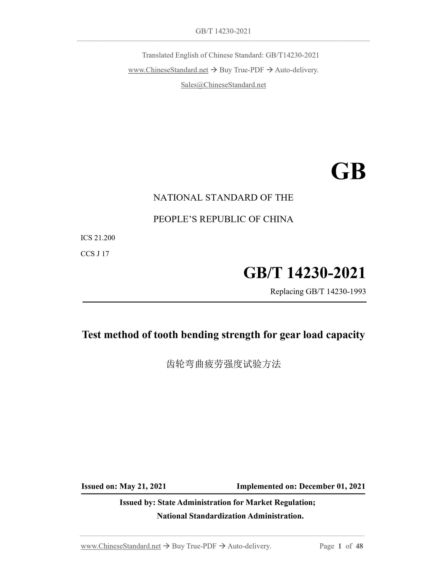
GB/T 14230-2021: Test method of tooth bending strength for gear load capacity
GB/T 14230-2021
GB
NATIONAL STANDARD OF THE
PEOPLE’S REPUBLIC OF CHINA
ICS 21.200
CCS J 17
Replacing GB/T 14230-1993
Test method of tooth bending strength for gear load capacity
ISSUED ON. MAY 21, 2021
IMPLEMENTED ON. DECEMBER 01, 2021
Issued by. State Administration for Market Regulation;
National Standardization Administration.
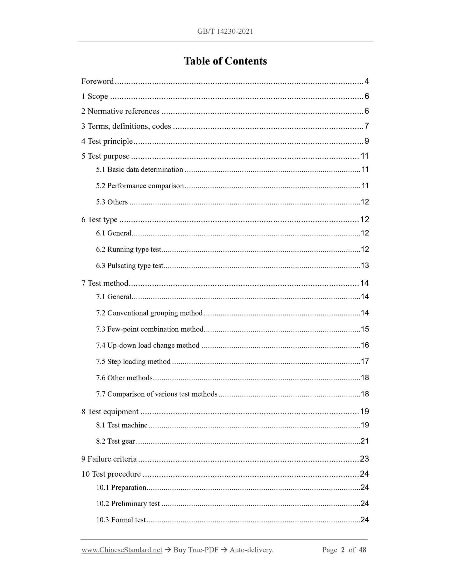
Table of Contents
Foreword... 4
1 Scope... 6
2 Normative references... 6
3 Terms, definitions, codes... 7
4 Test principle... 9
5 Test purpose... 11
5.1 Basic data determination... 11
5.2 Performance comparison... 11
5.3 Others... 12
6 Test type... 12
6.1 General... 12
6.2 Running type test... 12
6.3 Pulsating type test... 13
7 Test method... 14
7.1 General... 14
7.2 Conventional grouping method... 14
7.3 Few-point combination method... 15
7.4 Up-down load change method... 16
7.5 Step loading method... 17
7.6 Other methods... 18
7.7 Comparison of various test methods... 18
8 Test equipment... 19
8.1 Test machine... 19
8.2 Test gear... 21
9 Failure criteria... 23
10 Test procedure... 24
10.1 Preparation... 24
10.2 Preliminary test... 24
10.3 Formal test... 24
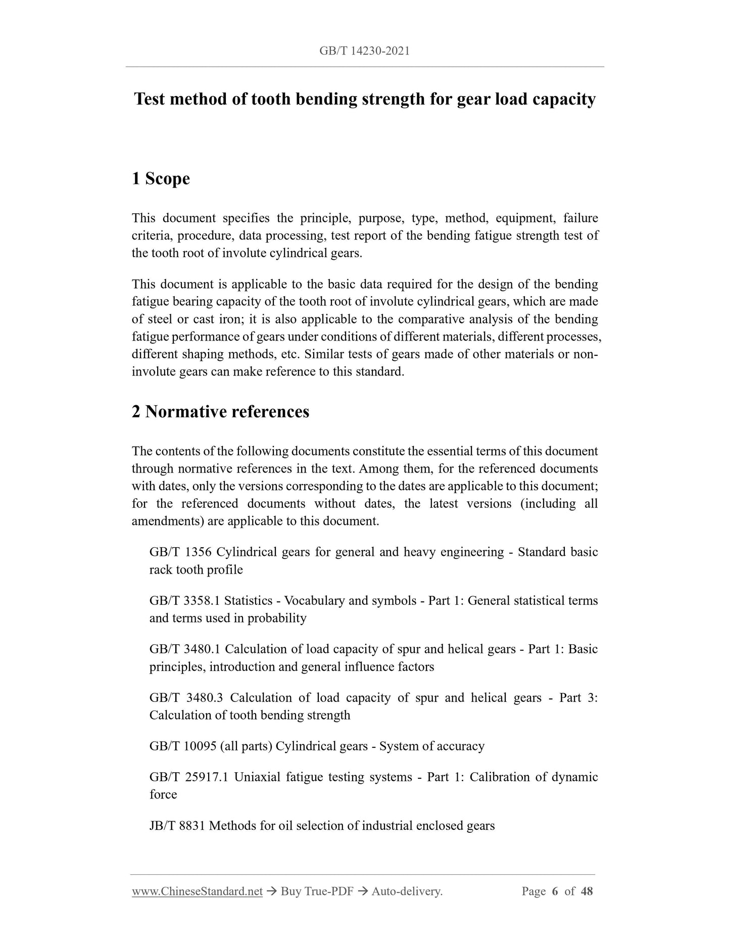
Test method of tooth bending strength for gear load capacity
1 Scope
This document specifies the principle, purpose, type, method, equipment, failure
criteria, procedure, data processing, test report of the bending fatigue strength test of
the tooth root of involute cylindrical gears.
This document is applicable to the basic data required for the design of the bending
fatigue bearing capacity of the tooth root of involute cylindrical gears, which are made
of steel or cast iron; it is also applicable to the comparative analysis of the bending
fatigue performance of gears under conditions of different materials, different processes,
different shaping methods, etc. Similar tests of gears made of other materials or non-
involute gears can make reference to this standard.
2 Normative references
The contents of the following documents constitute the essential terms of this document
through normative references in the text. Among them, for the referenced documents
with dates, only the versions corresponding to the dates are applicable to this document;
for the referenced documents without dates, the latest versions (including all
amendments) are applicable to this document.
GB/T 1356 Cylindrical gears for general and heavy engineering - Standard basic
rack tooth profile
GB/T 3358.1 Statistics - Vocabulary and symbols - Part 1.General statistical terms
and terms used in probability
GB/T 3480.1 Calculation of load capacity of spur and helical gears - Part 1.Basic
principles, introduction and general influence factors
GB/T 3480.3 Calculation of load capacity of spur and helical gears - Part 3.
Calculation of tooth bending strength
GB/T 10095 (all parts) Cylindrical gears - System of accuracy
GB/T 25917.1 Uniaxial fatigue testing systems - Part 1.Calibration of dynamic
force
JB/T 8831 Methods for oil selection of industrial enclosed gears
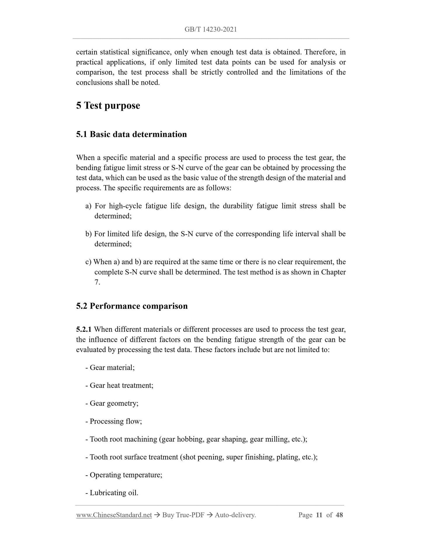
certain statistical significance, only when enough test data is obtained. Therefore, in
practical applications, if only limited test data points can be used for analysis or
comparison, the test process shall be strictly controlled and the limitations of the
conclusions shall be noted.
5 Test purpose
5.1 Basic data determination
When a specific material and a specific process are used to process the test gear, the
bending fatigue limit stress or S-N curve of the gear can be obtained by processing the
test data, which can be used as the basic value of the strength design of the material and
process. The specific requirements are as follows.
a) For high-cycle fatigue life design, the durability fatigue limit stress shall be
determined;
b) For limited life design, the S-N curve of the corresponding life interval shall be
determined;
c) When a) and b) are required at the same time or there is no clear requirement, the
complete S-N curve shall be determined. The test method is as shown in Chapter
7.
5.2 Performance comparison
5.2.1 When different materials or different processes are used to process the test gear,
the influence of different factors on the bending fatigue strength of the gear can be
evaluated by processing the test data. These factors include but are not limited to.
- Gear material;
- Gear heat treatment;
- Gear geometry;
- Processing flow;
- Tooth root machining (gear hobbing, gear shaping, gear milling, etc.);
- Tooth root surface treatment (shot peening, super finishing, plating, etc.);
- Operating temperature;
- Lubricating oil.
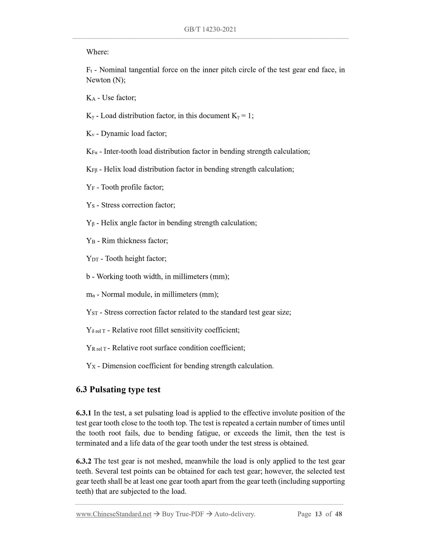
Where.
Ft - Nominal tangential force on the inner pitch circle of the test gear end face, in
Newton (N);
KA - Use factor;
Kγ - Load distribution factor, in this document Kγ = 1;
Kv - Dynamic load factor;
KFα - Inter-tooth load distribution factor in bending strength calculation;
KFβ - Helix load distribution factor in bending strength calculation;
YF - Tooth profile factor;
YS - Stress correction factor;
Yβ - Helix angle factor in bending strength calculation;
YB - Rim thickness factor;
YDT - Tooth height factor;
b - Working tooth width, in millimeters (mm);
mn - Normal module, in millimeters (mm);
YST - Stress correction factor related to the standard test gear size;
Yδ rel T - Relative root fillet sensitivity coefficient;
YR rel T - Relative root surface condition coefficient;
YX - Dimension coefficient for bending strength calculation.
6.3 Pulsating type test
6.3.1 In the test, a set pulsating load is applied to the effective involute position of the
test gear tooth close to the tooth top. The test is repeated a certain number of times until
the tooth root fails, due to bending fatigue, or exceeds the limit, then the test is
terminated and a life data of the gear tooth under the test stress is obtained.
6.3.2 The test gear is not meshed, meanwhile the load is only applied to the test gear
teeth. Several test points can be obtained for each test gear; however, the selected test
gear teeth shall be at least one gear tooth apart from the gear teeth (including supporting
teeth) that are subjected to the load.
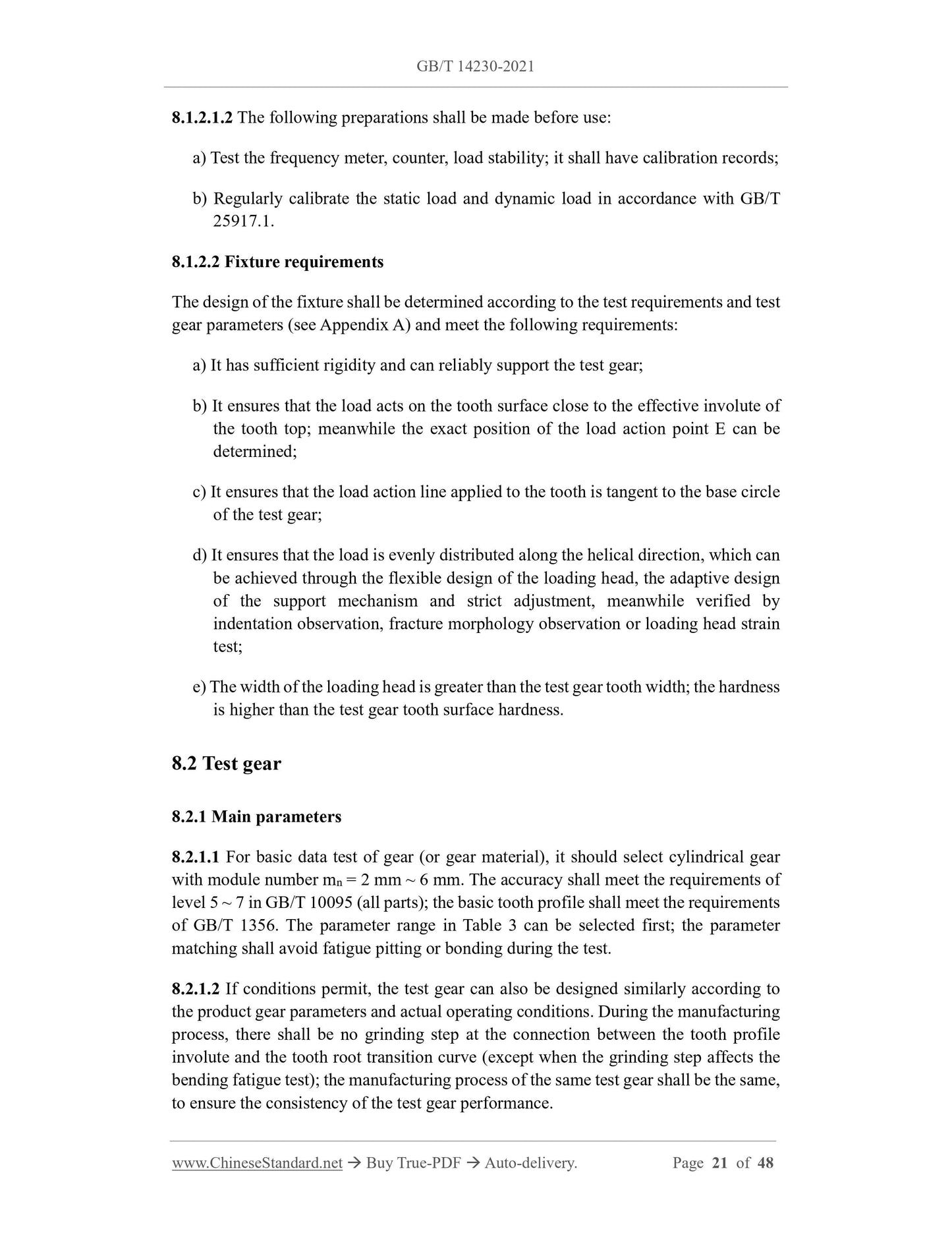
8.1.2.1.2 The following preparations shall be made before use.
a) Test the frequency meter, counter, load stability; it shall have calibration records;
b) Regularly calibrate the static load and dynamic load in accordance with GB/T
25917.1.
8.1.2.2 Fixture requirements
The design of the fixture shall be determined according to the test requirements and test
gear parameters (see Appendix A) and meet the following requirements.
a) It has sufficient rigidity and can reliably support the test gear;
b) It ensures that the load acts on the tooth surface close to the effective involute of
the tooth top; meanwhile the exact position of the load action point E can be
determined;
c) It ensures that the load action line applied to the tooth is tangent to the base circle
of the test gear;
d) It ensures that the load is evenly distributed along the helical direction, which can
be achieved through the flexible design of the loading head, the adaptive design
of the support mechanism and strict adjustment, meanwhile verified by
indentation observation, fracture morphology observation or loading head strain
test;
e) The width of the loading head is greater than the test gear tooth width; the hardness

View full details