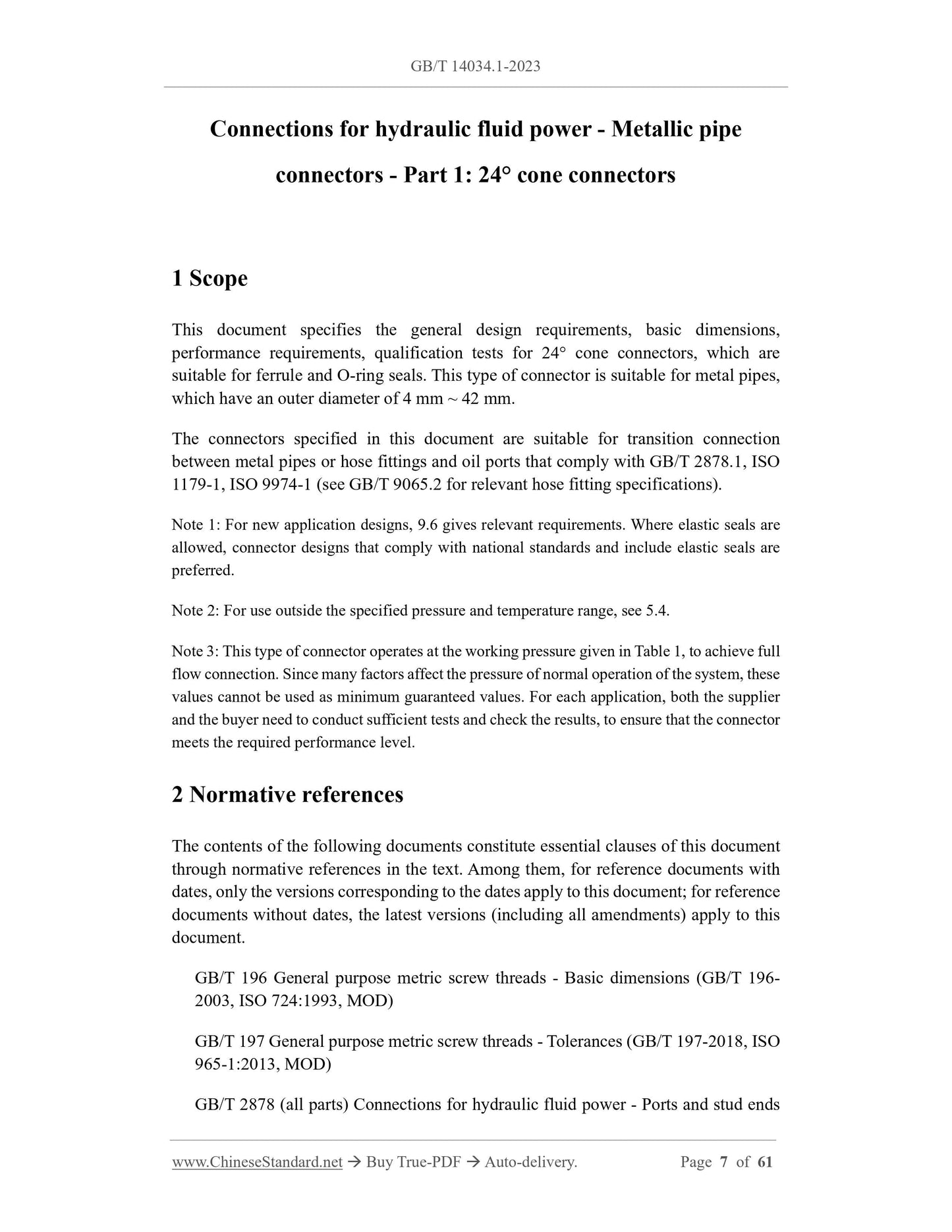
This document specifies the general design requirements, basic dimensions, performance requirements, qualification tests for 24° cone connectors, which are suitable for ferrule and O-ring seals. This type of connector is suitable for metal pipes, which have an outer diameter of 4 mm ~ 42 mm.
Basic Data
Standard ID
GB/T 14034.1-2023 (GB/T14034.1-2023)
Description (Translated English)
Connections for hydraulic fluid power - Metallic tube connectors - Part 1: 24�� cone connectors
Sector / Industry
National Standard (Recommended)
Classification of Chinese Standard
J20
Classification of International Standard
23.100.40
Word Count Estimation
54,574
Date of Issue
2023-08-06
Date of Implementation
2023-08-06
Older Standard (superseded by this standard)
GB/T 14034.1-2010
Issuing agency(ies)
State Administration for Market Regulation, China National Standardization Administration