Skip to product information
1 of 7

PayPal, credit cards. Download editable-PDF & invoice In 1 second!

GB/T 13871.1-2022 English PDF (GBT13871.1-2022)

GB/T 13871.1-2022 English PDF (GBT13871.1-2022)

Regular price $320.00 USD
Regular price Sale price $320.00 USD
Sale Sold out
Shipping calculated at checkout.
Delivery: 3 seconds. Download true-PDF + Invoice.
Get QUOTATION in 1-minute: Click GB/T 13871.1-2022
Historical versions: GB/T 13871.1-2022
Preview True-PDF (Reload/Scroll if blank)

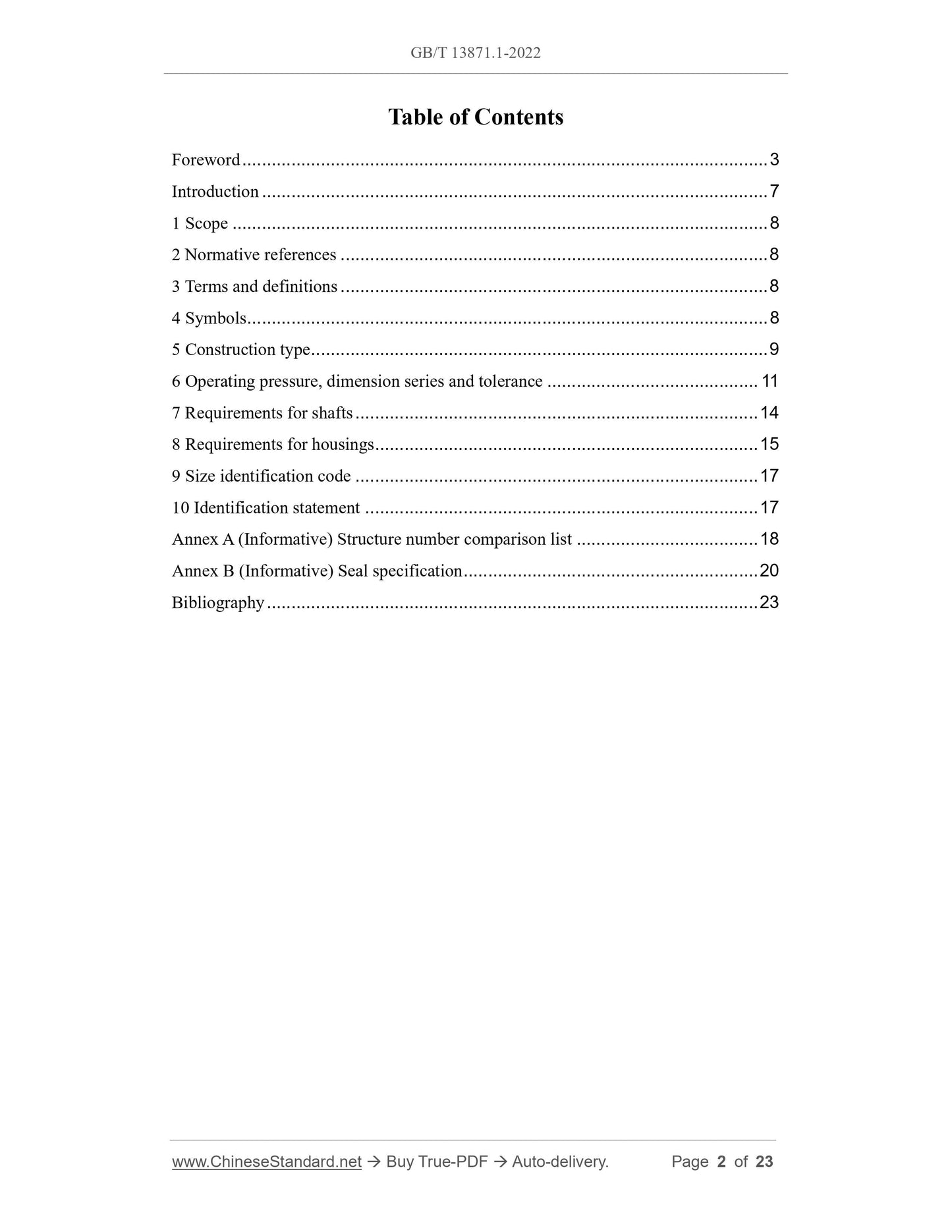
GB/T 13871.1-2022: Rotary shaft lip-type seals incorporatingelastomeric sealing elements - Part 1: Dimensions and tolerances
GB/T 13871.1-2022
GB
NATIONAL STANDARD OF THE
PEOPLE’S REPUBLIC OF CHINA
ICS 83.140.50;23.100.60
CCS G 43
Replacing GB/T 13871.1-2007
Rotary shaft lip-type seals incorporating elastomeric sealing
elements - Part 1: Dimensions and tolerances
(ISO 6194-1:2007, Rotary shaft lip-type seals incorporating elastomeric sealing
elements - Part 1: Nominal dimensions and tolerances, MOD)
ISSUED ON: OCTOBER 12, 2022
IMPLEMENTED ON: MAY 01, 2023
Issued by: State Administration for Market Regulation;
Standardization Administration of the People’s Republic of China.
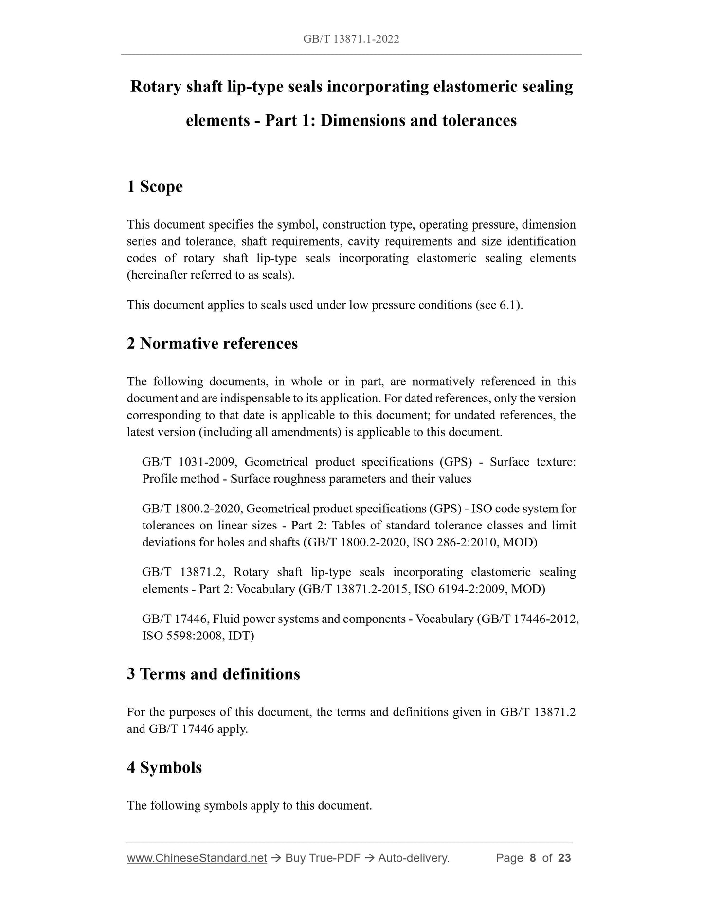
Table of Contents
Foreword ... 3
Introduction ... 7
1 Scope ... 8
2 Normative references ... 8
3 Terms and definitions ... 8
4 Symbols ... 8
5 Construction type ... 9
6 Operating pressure, dimension series and tolerance ... 11
7 Requirements for shafts ... 14
8 Requirements for housings ... 15
9 Size identification code ... 17
10 Identification statement ... 17
Annex A (Informative) Structure number comparison list ... 18
Annex B (Informative) Seal specification ... 20
Bibliography ... 23
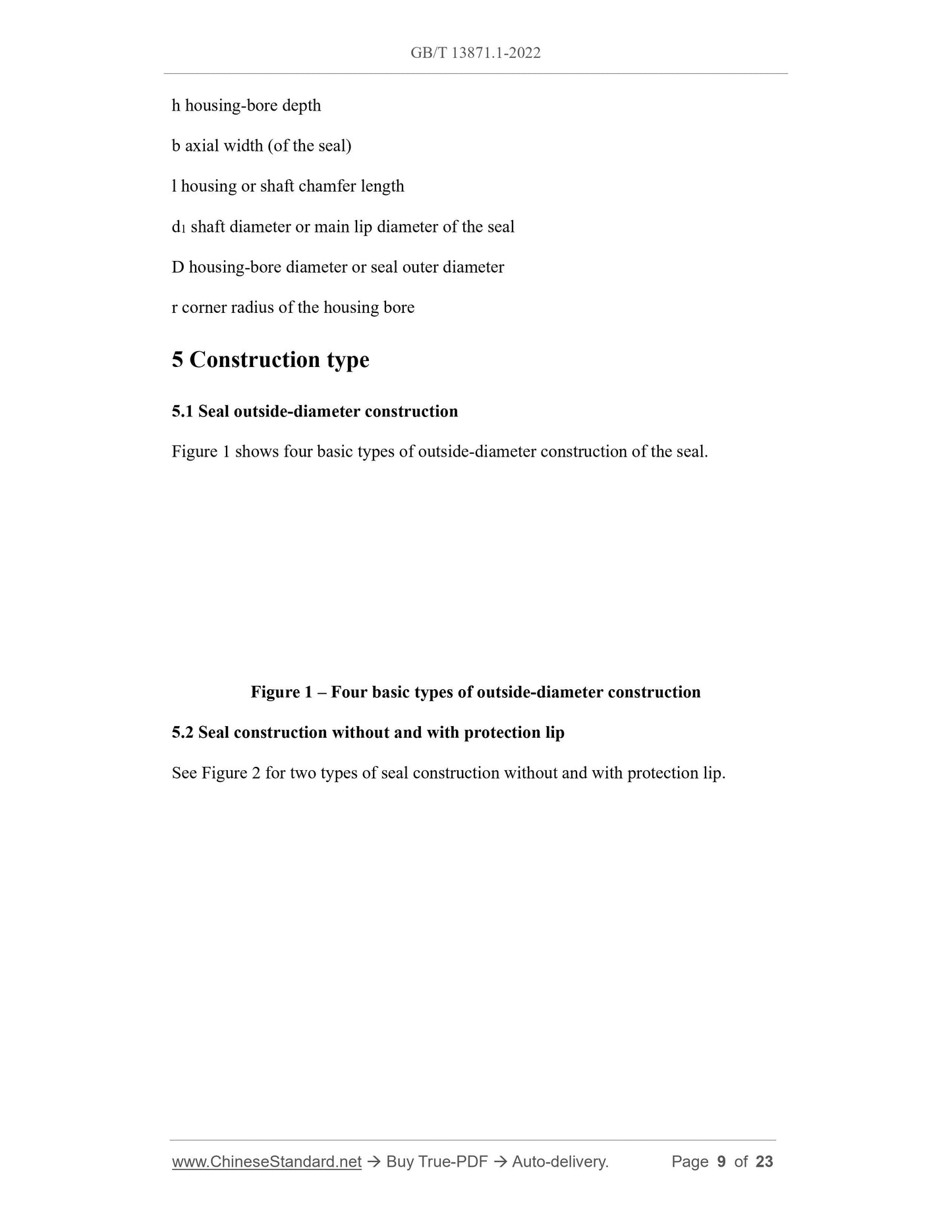
Rotary shaft lip-type seals incorporating elastomeric sealing
elements - Part 1: Dimensions and tolerances
1 Scope
This document specifies the symbol, construction type, operating pressure, dimension
series and tolerance, shaft requirements, cavity requirements and size identification
codes of rotary shaft lip-type seals incorporating elastomeric sealing elements
(hereinafter referred to as seals).
This document applies to seals used under low pressure conditions (see 6.1).
2 Normative references
The following documents, in whole or in part, are normatively referenced in this
document and are indispensable to its application. For dated references, only the version
corresponding to that date is applicable to this document; for undated references, the
latest version (including all amendments) is applicable to this document.
GB/T 1031-2009, Geometrical product specifications (GPS) - Surface texture:
Profile method - Surface roughness parameters and their values
GB/T 1800.2-2020, Geometrical product specifications (GPS) - ISO code system for
tolerances on linear sizes - Part 2: Tables of standard tolerance classes and limit
deviations for holes and shafts (GB/T 1800.2-2020, ISO 286-2:2010, MOD)
GB/T 13871.2, Rotary shaft lip-type seals incorporating elastomeric sealing
elements - Part 2: Vocabulary (GB/T 13871.2-2015, ISO 6194-2:2009, MOD)
GB/T 17446, Fluid power systems and components - Vocabulary (GB/T 17446-2012,
ISO 5598:2008, IDT)
3 Terms and definitions
For the purposes of this document, the terms and definitions given in GB/T 13871.2
and GB/T 17446 apply.
4 Symbols
The following symbols apply to this document.
h housing-bore depth
b axial width (of the seal)
l housing or shaft chamfer length
d1 shaft diameter or main lip diameter of the seal
D housing-bore diameter or seal outer diameter
r corner radius of the housing bore
5 Construction type
5.1 Seal outside-diameter construction
Figure 1 shows four basic types of outside-diameter construction of the seal.
Figure 1 – Four basic types of outside-diameter construction
5.2 Seal construction without and with protection lip
See Figure 2 for two types of seal construction without and with protection lip.
See Figure 3 for the schematic diagram of the common construction of air-side surface
of the sealing lip.
Figure 3 – Construction of air-side surface of the sealing lip
5.4 Construction of the rubber-covered metal-cased seal
See Figure 4 for the schematic diagram of the common construction of the rubber-
covered metal-cased seal.
5.5 Construction code of the seal
The various constructions shown in Figure 1, Figure 2, and Figure 3 can be combined
and applied with each other, and the construction codes could be as follows:
-- Single letters W, Z and B (see Figure 1) indicate the seal construction without
protection lip and without wave-profile;
-- Two-letters FB, FW and FZ, starting with F, indicate the seal construction with
protection lip and without wave-profile; F indicates the existing of a protection
lip, and the second letter indicates the outside-diameter construction (see Figure
1);
-- Two-letters WL, ZL, BL, WR, ZR and BR, not beginning with F, indicate the seal
construction without protection lip and with wave-profile; the first letter indicates
the outside-diameter construction (see Figure 1), and the second letter indicates
the direction of the wave-profile (see Figure 3);
-- Three-letters FBL, FWL, FZL, FBR, FWR and FZR indicate the seal construction
with protection lip and with wave-profile; the first letter F indicates the existing
of the protection lip, the second letter indicates the outside-diameter construction
(see Figure 1), and the third letter indicates the direction of the wave-profile (see
Figure 3).
The design of the sealing lip is mainly carried out by the manufacturer (to ensure
sealing); it can also be agreed between the manufacturer and the buyer.
Note: The constructions shown are only representative examples of the basic types. For
the specific design details, refer to GB/T 9877-2008.
6 Operating pressure, dimension series and tolerance
6.1 Operating pressure
Seals are normally used with atmospheric pressure on the air side, and sealing fluids at
pressures of 0 kPa ~ 50 kPa above atmospheric pressure. The user shall consult the seal
manufacturer regarding use at other pressures.
6.2 Dimension series
The assembling diagram of the seal is shown in Figure 5 and the dimension series are
given in Table 1.
7.2 Diametral tolerance
The shaft shall have a diametral tolerance not greater than h11 as specified in GB/T
1800.2-2020.
7.3 Surface roughness and hardness
7.3.1 Surface roughness
The seal contact surface of a ground shaft shall be finished to a surface roughness,
measured in the axial direction of Ra 0.2 μm ~ Ra 0.8 μm, or Rz 0.8 μm ~ Rz 3.2 μm,
as specified in GB/T 1031-2009.
If the surface roughness value of the shaft does not fall within the limits given in this
document, it shall be determined between the user and the seal manufacturer.
7.3.2 Surface hardness
The surface hardness of the shaft shall be a minimum of HRC30. If the surface hardness
of the shaft is less than HRC30, it shall be subject to agreement between the user and
the seal manufacturer.
8 Requirements for housings
8.1 Dimensions
8.1.1 Where the housing is a rigid fully machined ferrous part, the housing bore shall
conform to 8.2 and 8.3.
8.1.2 The housing bore shall be provided with a lead-in chamfer, free from burrs, as
shown in Figure 7 and specified in Table 6.

View full details