1
/
of
12
PayPal, credit cards. Download editable-PDF and invoice in 1 second!
GB/T 13286-2021 English PDF (GB/T13286-2021)
Regular price
$380.00 USD
Regular price
Sale price
$380.00 USD
Unit price
/
per
Shipping calculated at checkout.
Couldn't load pickup availability
Delivery: 3 seconds. Download true-PDF + Invoice.
Get Quotation: Click GB/T 13286-2021 (Self-service in 1-minute)
Historical versions (Master-website): GB/T 13286-2021
Preview True-PDF (Reload/Scroll-down if blank)
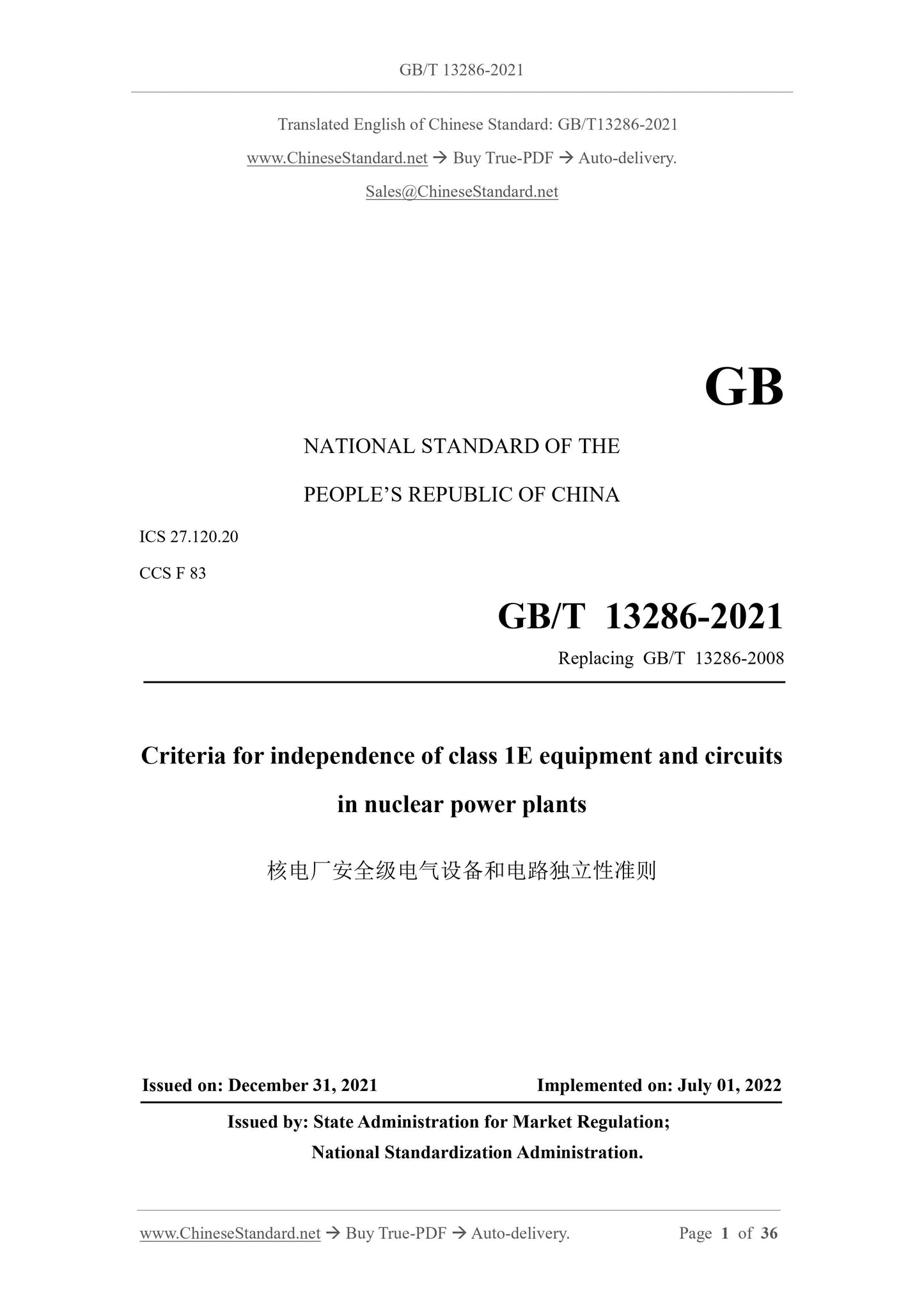
GB/T 13286-2021: Criteria for independence of class 1E equipment and circuits in nuclear power plants
GB/T 13286-2021
GB
NATIONAL STANDARD OF THE
PEOPLE’S REPUBLIC OF CHINA
ICS 27.120.20
CCS F 83
Replacing GB/T 13286-2008
Criteria for independence of class 1E equipment and circuits
in nuclear power plants
ISSUED ON: DECEMBER 31, 2021
IMPLEMENTED ON: JULY 01, 2022
Issued by: State Administration for Market Regulation;
National Standardization Administration.
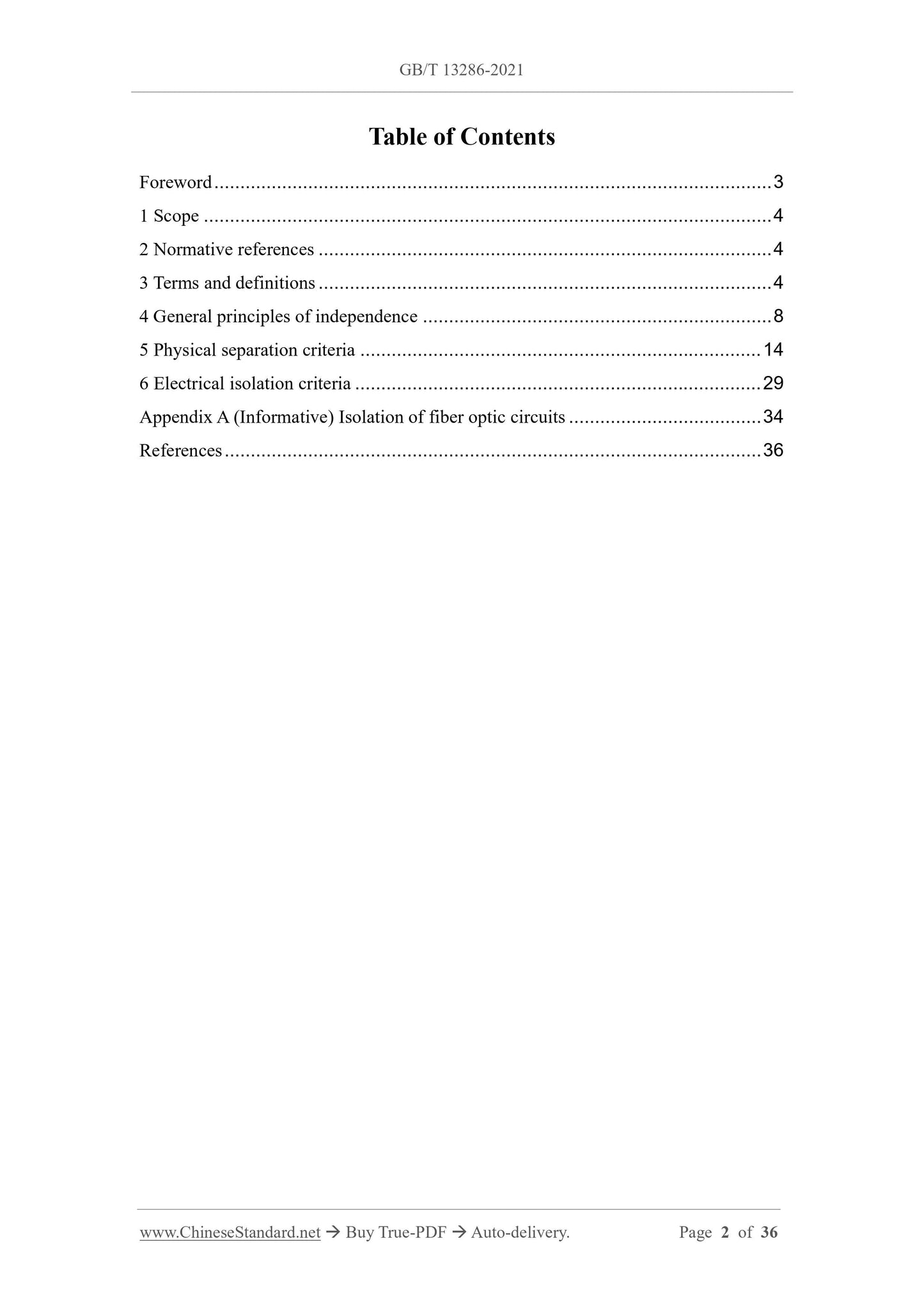
Table of Contents
Foreword ... 3
1 Scope ... 4
2 Normative references ... 4
3 Terms and definitions ... 4
4 General principles of independence ... 8
5 Physical separation criteria ... 14
6 Electrical isolation criteria ... 29
Appendix A (Informative) Isolation of fiber optic circuits ... 34
References ... 36
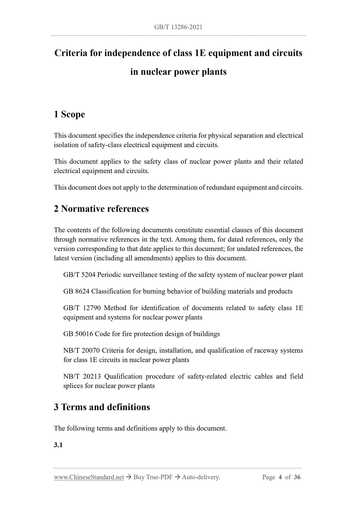
Criteria for independence of class 1E equipment and circuits
in nuclear power plants
1 Scope
This document specifies the independence criteria for physical separation and electrical
isolation of safety-class electrical equipment and circuits.
This document applies to the safety class of nuclear power plants and their related
electrical equipment and circuits.
This document does not apply to the determination of redundant equipment and circuits.
2 Normative references
The contents of the following documents constitute essential clauses of this document
through normative references in the text. Among them, for dated references, only the
version corresponding to that date applies to this document; for undated references, the
latest version (including all amendments) applies to this document.
GB/T 5204 Periodic surveillance testing of the safety system of nuclear power plant
GB 8624 Classification for burning behavior of building materials and products
GB/T 12790 Method for identification of documents related to safety class 1E
equipment and systems for nuclear power plants
GB 50016 Code for fire protection design of buildings
NB/T 20070 Criteria for design, installation, and qualification of raceway systems
for class 1E circuits in nuclear power plants
NB/T 20213 Qualification procedure of safety-related electric cables and field
splices for nuclear power plants
3 Terms and definitions
The following terms and definitions apply to this document.
3.1
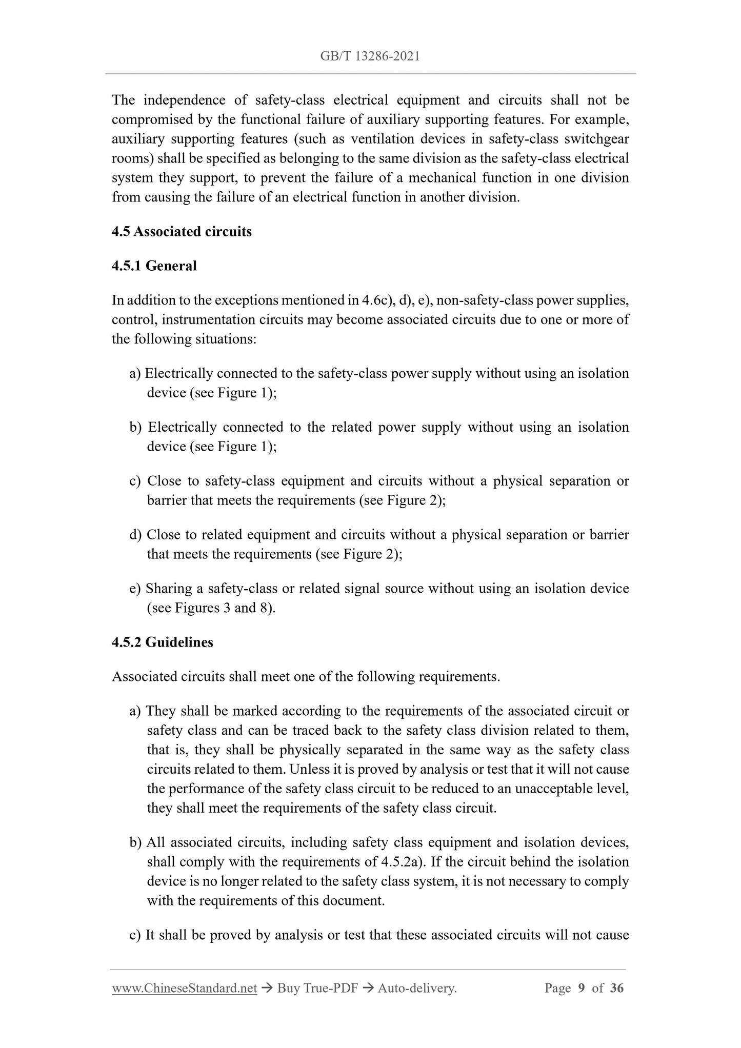
The independence of safety-class electrical equipment and circuits shall not be
compromised by the functional failure of auxiliary supporting features. For example,
auxiliary supporting features (such as ventilation devices in safety-class switchgear
rooms) shall be specified as belonging to the same division as the safety-class electrical
system they support, to prevent the failure of a mechanical function in one division
from causing the failure of an electrical function in another division.
4.5 Associated circuits
4.5.1 General
In addition to the exceptions mentioned in 4.6c), d), e), non-safety-class power supplies,
control, instrumentation circuits may become associated circuits due to one or more of
the following situations:
a) Electrically connected to the safety-class power supply without using an isolation
device (see Figure 1);
b) Electrically connected to the related power supply without using an isolation
device (see Figure 1);
c) Close to safety-class equipment and circuits without a physical separation or
barrier that meets the requirements (see Figure 2);
d) Close to related equipment and circuits without a physical separation or barrier
that meets the requirements (see Figure 2);
e) Sharing a safety-class or related signal source without using an isolation device
(see Figures 3 and 8).
4.5.2 Guidelines
Associated circuits shall meet one of the following requirements.
a) They shall be marked according to the requirements of the associated circuit or
safety class and can be traced back to the safety class division related to them,
that is, they shall be physically separated in the same way as the safety class
circuits related to them. Unless it is proved by analysis or test that it will not cause
the performance of the safety class circuit to be reduced to an unacceptable level,
they shall meet the requirements of the safety class circuit.
b) All associated circuits, including safety class equipment and isolation devices,
shall comply with the requirements of 4.5.2a). If the circuit behind the isolation
device is no longer related to the safety class system, it is not necessary to comply
with the requirements of this document.
c) It shall be proved by analysis or test that these associated circuits will not cause
2) Through analysis, it is proved that the non-safety circuit will not cause the
performance of the safety circuit to be degraded to an unacceptable level. The
analysis shall evaluate the category of the non-safety circuit and its possible
energy.
e) Non-safety fiber optic loops do not need to be physically isolated from safety
circuits or associated circuits. Electrical isolation is an inherent characteristic of
fiber optic loops. Because fiber optic loops do not cause the safety circuit to
degrade, they can be treated as non-safety circuits rather than associated circuits.
4.7 Mechanical system
Safety-class circuits shall be laid or protected in a manner that prevents failure of a
division of mechanical equipment from causing failure of safety-class circuits or
equipment necessary for redundant systems or equipment to perform their safety
functions. When safety-class equipment or circuits are used to mitigate the
consequences of a mechanical system failure or misoperation, the impact of these
failures or mis-operations on the division itself shall be evaluated. At the same time, the
impact of pipe swing, jet impact, water spray, flooding, radiation, pressurization,
temperature rise or moisture on redundant electrical systems, as caused by mechanical
system failure, misoperation or operation, shall be evaluated. In addition, the potential
hazards of flying objects caused by rotating equipment or high-energy system failures
shall also be evaluated.
4.8 Structures and equipment
Safety-class electrical systems shall maintain their independence and redundancy
during and after the failure of structures and equipment that have not been identified
for design basis events.
4.9 Fire protection system
When redundant division equipment and circuits are arranged within the range of the
same fixed fire protection system, the design of these equipment and circuits shall be
coordinated with the fire protection system, so that the independence of the safety-class
electrical system is not impaired; the impact of false operation of the fire protection
system on equipment rooms and cable channels shall be evaluated.
4.10 Fire
4.10.1 An electrical fire occurring within a safety class division shall not cause the loss
of function of its redundant division.
4.10.2 Redundant safety class equipment and circuits shall maintain independence; a
fire in a fire hazardous area shall not prevent its redundant equipment and circuits from
performing safety functions.
4.11 Electromagnetic interference/Radio frequency interference
The possibility of electromagnetic interference/radio frequency interference affecting
the independence of redundant safety class equipment and circuits shall be evaluated.
Corrective measures to mitigate electromagnetic interference/radio frequency
interference interactions may include the following: grounding, use of low-voltage
components, physical separation, isolation devices, shielding of susceptible equipment
or circuits, shielding of electromagnetic interference sources, etc., see Appendix B of
GB/T 13284.1-2008.
The following interactions of EMI/RFI shall be evaluated:
a) EMI/RFI generated by a safety class division shall not reduce the ability of
redundant safety class equipment or circuits to perform safety functions;
b) EMI/RFI generated outside the safety class circuit (such as non-safety class
circuits and equipment, broadcasting, telephone) shall not reduce the ability of
safety class equipment and circuits to perform safety functions.
5 Physical separation criteria
5.1 Cable and wiring channels
5.1.1 General
5.1.1.1 Grading of areas
The cable laying and equipment areas of the safety class and its associated circuits shall
be reviewed, to find out whether there are potential hazards such as high-energy
pipelines, flying objects, flammable materials, ignition sources and flooding. These
areas shall be divided as follows:
a) Non-hazardous areas (see 5.1.3);
b) Low-hazard areas (see 5.1.4);
c) Hazardous areas (see 5.1.5).
In the early stages of design, a separation equivalent to the degree of potential hazardous
damage shall be provided through separate rooms, barriers and other facilities. If there
is sufficient heat dissipation capacity, the sides of the room or area can also be used as
a partition.
5.1.1.2 Minimum separation distance
5.1.1.2.1 Subject to the following criteria, the minimum separation distances specified
in 5.1.3 ~ 5.1.5 and 5.1.9 can be used to obtain a physical separation that meets the
the consequences (such as spraying devices) shall be evaluated.
5.1.2 Marking
Exposed safety-class and associated circuit cable wiring channels shall be permanently
marked at the entrances and exits of the enclosed area and at intervals of no more than
5 m on the channel. The marking shall be set before the cable is installed. Cables laid
in the wiring channel shall be permanently marked at intervals of no more than 3 m, so
that it can be verified from the beginning whether their laying meets the separation
criteria. The marking shall be set before or during the cable laying.
Cables of safety class and associated circuits shall be permanently marked at each end
in accordance with the requirements of the design drawings or cable lists.
To meet the above requirements, the marking method adopted shall be able to easily
distinguish between redundant safety class divisions, safety class and non-safety class
divisions, associated cables of different redundant safety class divisions. If no
separation is required between optical fiber loops, a single method can be used for
identification.
5.1.3 Non-hazardous area
5.1.3.1 Area requirements
The basis for determining the minimum separation distance applicable to this area is
limited to internal faults of electrical equipment and cables.
The area that meets the following requirements is defined as a non-hazardous area:
a) There are no high-energy equipment (such as switchgear, transformers, rotating
equipment) in this area, nor are there any potential hazards such as missiles,
pipeline damage or fire;
b) The circuits in this area shall be limited to instrumentation and control functions,
as well as power equipment and cables that only serve the equipment in this area;
c) The power cables in this area shall be installed in closed wiring channels;
d) The introduction of potential hazards shall be limited and controlled through
administrative measures for operation and maintenance activities.
5.1.3.2 Boundary of non-hazardous areas
The boundary of non-hazardous areas meets the following requirements:
a) The area shall be separated from other adjacent areas by a fire barrier, which shall
have a fire resistance equivalent to the possible fire hazard, or shall have a fire
resistance rating of 3 h;
In the hazardous area, comprehensive measures such as restrictions on cable laying or
special physical separation shall be adopted according to the requirements of 5.1.6 ~
5.1.8, to keep the independence of the redundant division of the safety class system
within an acceptable level.
The minimum distance between the non-safety class and the safety class or associated
circuits shall meet the requirements of 5.1.4.
5.1.6 Pipeline damage hazardous area
5.1.6.1 Area requirements
If there are pipelines operating normally at high or medium energy in a certain area, the
area shall be defined as a pipeline damage dangerous area.
For medium energy pipelines, it is not necessary to consider pipeline swing and jet
impact, but the impact on the surrounding area and the environment shall be evaluated.
5.1.6.2 Area boundary
Barriers, constraints, separation distances or appropriate combinations thereof shall be
used to protect non-hazardous areas and low-hazardous areas from the hazards of
pipeline damage hazardous areas.
5.1.6.3 Laying requirements
In the pipeline damage hazardous area, it shall be possible to prove that the pipeline
damage does not affect the ability of the safety-class equipment and circuits to perform
their safety functions. Otherwise, the laying of cables or wiring channels for safety-
class or associated circuits shall meet the following requirements.
a) If the relevant pipeline does not belong to a single division and has been qualified
by the design basis event, meanwhile no protective action is required for the
impact caused by its damage, the cables or wiring channels for the safety-class or
associated circuits laid in the area shall be limited to a single division.
b) If protective action is required for the impact caused by the damage to the pipeline,
except for the cables that shall be terminated to the devices or loads in the area
[special measures (such as increasing redundancy or diversity) may be required
for these cables to meet the single failure criterion], cables or wiring channels for
other safety-class or associated circuits shall not be laid in the area.
c) If the relevant pipeline belongs to a single division and has been qualified by the
design basis event, meanwhile no protective action is required for the impact
caused by its damage, the cables or wiring channels for the safety-class or
associated circuits laid in the area shall be limited to the same division as the
pipeline.
d) If the relevant pipeline has not been identified for design basis events, cables or
wiring channels of other safety-class or associated circuits shall not be laid in the
area, except for cables that shall be terminated to devices or loads in the area.
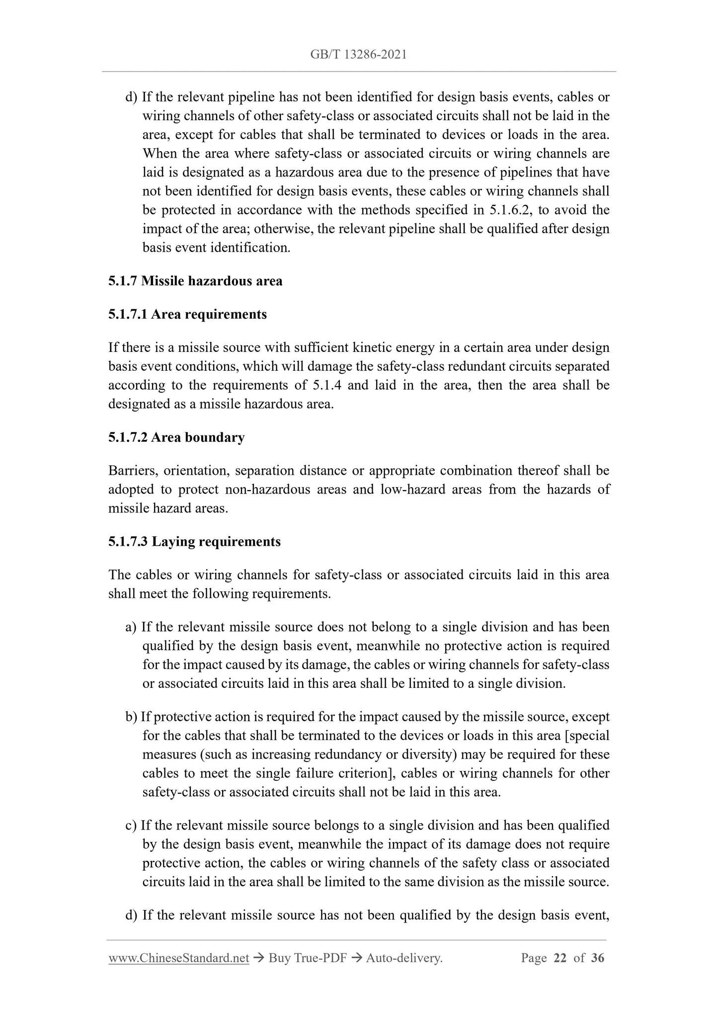
When the area wh...
Share