Skip to product information
1 of 12

www.ChineseStandard.us -- Field Test Asia Pte. Ltd.

GB/T 12897-2006 English PDF (GB/T12897-2006)

GB/T 12897-2006 English PDF (GB/T12897-2006)

Regular price $560.00
Regular price Sale price $560.00
Sale Sold out
Shipping calculated at checkout.
GB/T 12897-2006: Specifications for the first and second order leveling
Delivery: 9 seconds. Download (& Email) true-PDF + Invoice.
Get Quotation: Click GB/T 12897-2006 (Self-service in 1-minute)
Historical versions (Master-website): GB/T 12897-2006
Preview True-PDF (Reload/Scroll-down if blank)

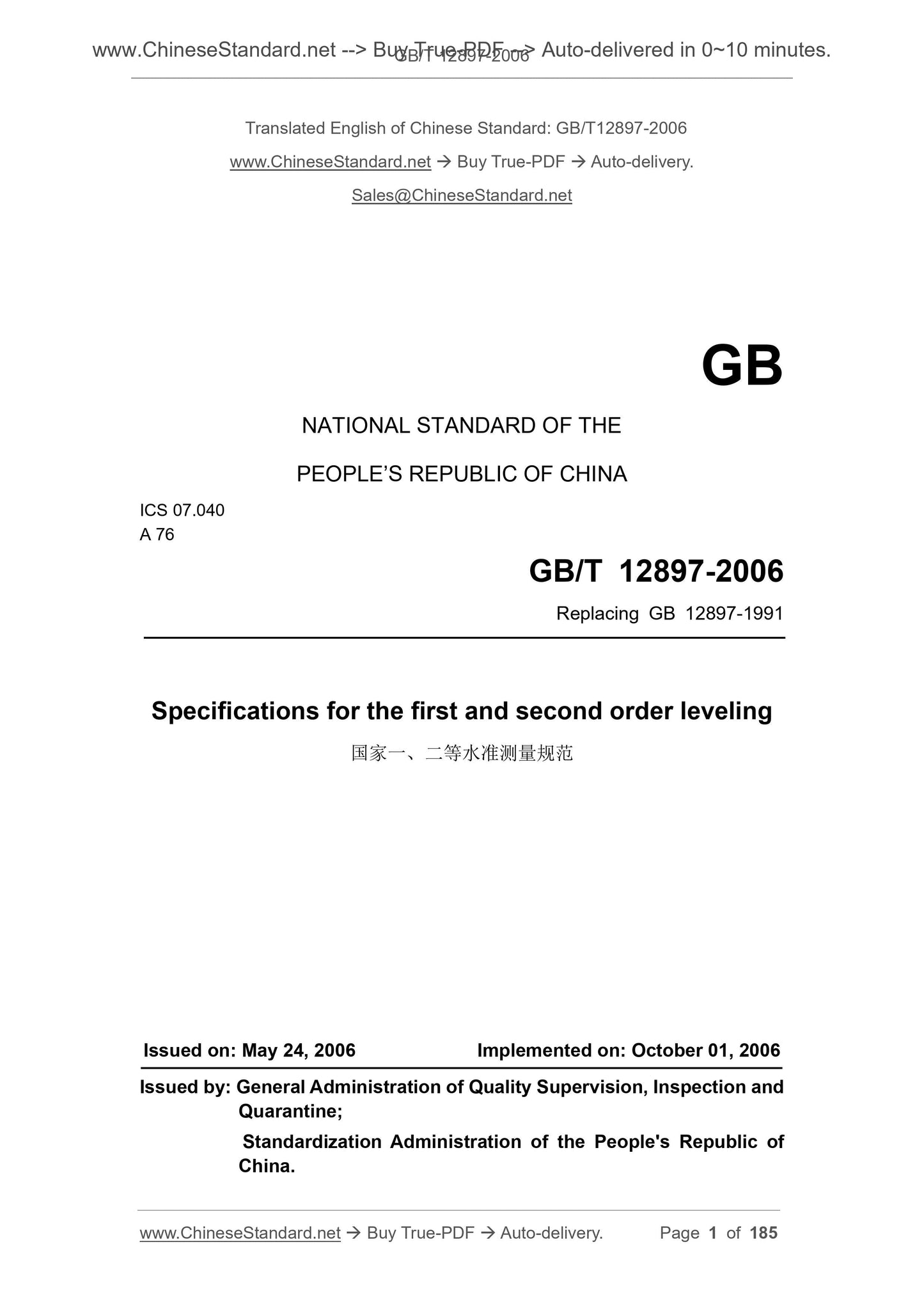
GB/T 12897-2006
GB
NATIONAL STANDARD OF THE
PEOPLE’S REPUBLIC OF CHINA
ICS 07.040
A 76
Replacing GB 12897-1991
Specifications for the first and second order leveling
ISSUED ON. MAY 24, 2006
IMPLEMENTED ON. OCTOBER 01, 2006
Issued by. General Administration of Quality Supervision, Inspection and
Quarantine;
Standardization Administration of the People's Republic of
China.
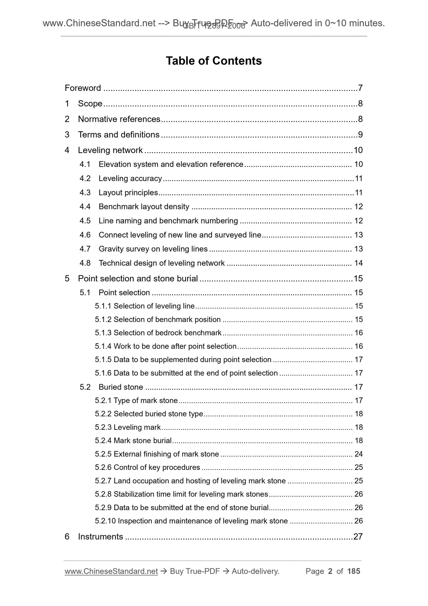
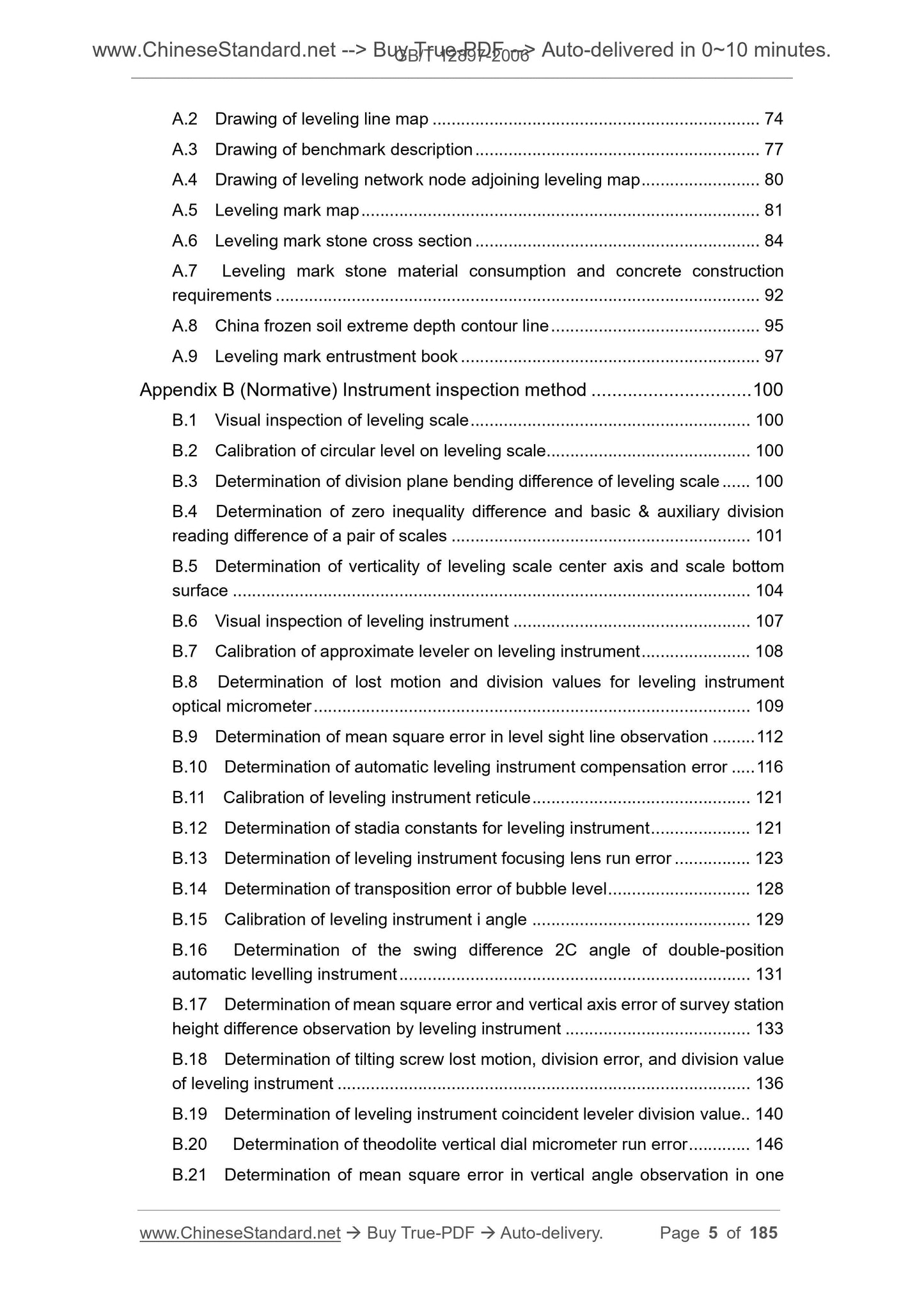
Table of Contents
Foreword ... 7 
1 Scope ... 8 
2 Normative references ... 8 
3 Terms and definitions ... 9 
4 Leveling network ... 10 
4.1 Elevation system and elevation reference ... 10 
4.2 Leveling accuracy ... 11 
4.3 Layout principles ... 11 
4.4 Benchmark layout density ... 12 
4.5 Line naming and benchmark numbering ... 12 
4.6 Connect leveling of new line and surveyed line ... 13 
4.7 Gravity survey on leveling lines ... 13 
4.8 Technical design of leveling network ... 14 
5 Point selection and stone burial ... 15 
5.1 Point selection ... 15 
5.1.1 Selection of leveling line ... 15 
5.1.2 Selection of benchmark position ... 15 
5.1.3 Selection of bedrock benchmark ... 16 
5.1.4 Work to be done after point selection ... 16 
5.1.5 Data to be supplemented during point selection ... 17 
5.1.6 Data to be submitted at the end of point selection ... 17 
5.2 Buried stone ... 17 
5.2.1 Type of mark stone ... 17 
5.2.2 Selected buried stone type ... 18 
5.2.3 Leveling mark ... 18 
5.2.4 Mark stone burial ... 18 
5.2.5 External finishing of mark stone ... 24 
5.2.6 Control of key procedures ... 25 
5.2.7 Land occupation and hosting of leveling mark stone ... 25 
5.2.8 Stabilization time limit for leveling mark stones ... 26 
5.2.9 Data to be submitted at the end of stone burial ... 26 
5.2.10 Inspection and maintenance of leveling mark stone ... 26 
6 Instruments ... 27 
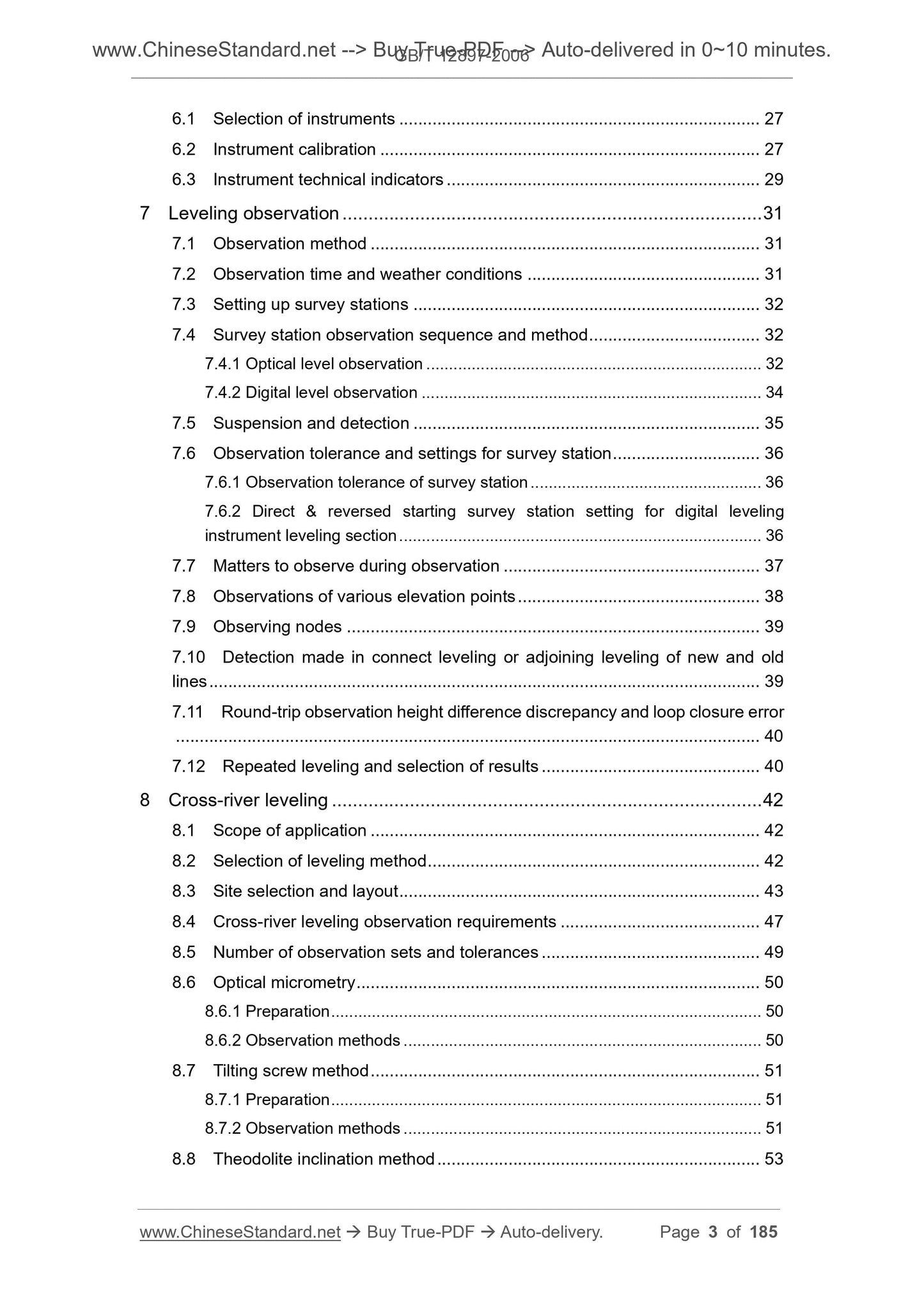
6.1 Selection of instruments ... 27 
6.2 Instrument calibration ... 27 
6.3 Instrument technical indicators ... 29 
7 Leveling observation ... 31 
7.1 Observation method ... 31 
7.2 Observation time and weather conditions ... 31 
7.3 Setting up survey stations ... 32 
7.4 Survey station observation sequence and method ... 32 
7.4.1 Optical level observation ... 32 
7.4.2 Digital level observation ... 34 
7.5 Suspension and detection ... 35 
7.6 Observation tolerance and settings for survey station ... 36 
7.6.1 Observation tolerance of survey station ... 36 
7.6.2 Direct and reversed starting survey station setting for digital leveling
instrument leveling section ... 36 
7.7 Matters to observe during observation ... 37 
7.8 Observations of various elevation points ... 38 
7.9 Observing nodes ... 39 
7.10 Detection made in connect leveling or adjoining leveling of new and old
lines ... 39 
7.11 Round-trip observation height difference discrepancy and loop closure error
... 40 
7.12 Repeated leveling and selection of results ... 40 
8 Cross-river leveling ... 42 
8.1 Scope of application ... 42 
8.2 Selection of leveling method ... 42 
8.3 Site selection and layout ... 43 
8.4 Cross-river leveling observation requirements ... 47 
8.5 Number of observation sets and tolerances ... 49 
8.6 Optical micrometry ... 50 
8.6.1 Preparation ... 50 
8.6.2 Observation methods ... 50 
8.7 Tilting screw method ... 51 
8.7.1 Preparation ... 51 
8.7.2 Observation methods ... 51 
8.8 Theodolite inclination method ... 53 
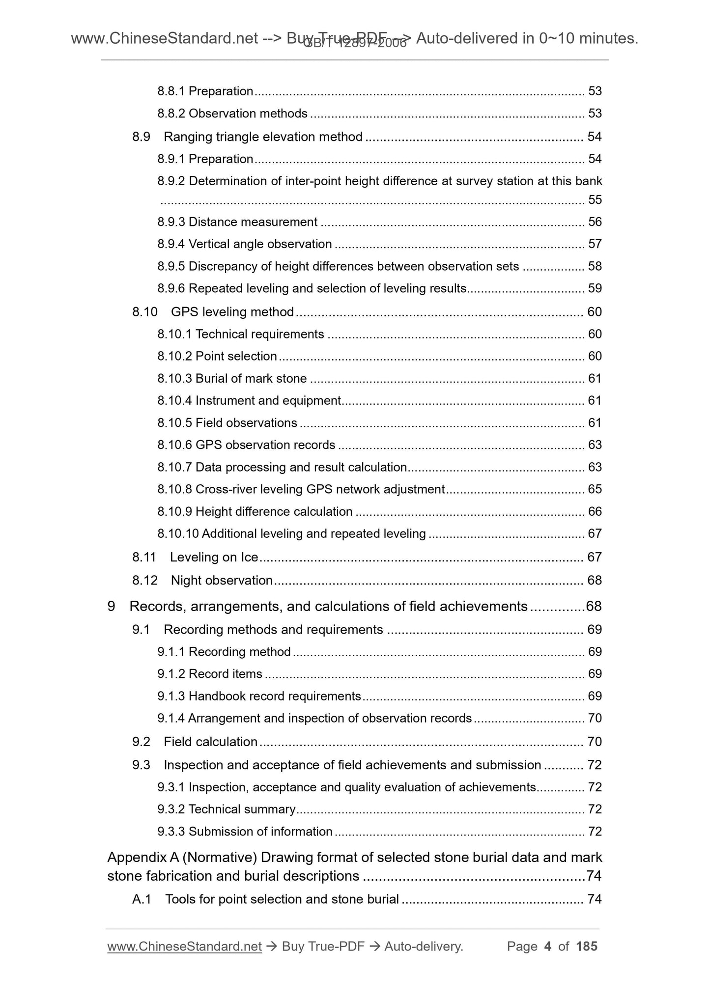
8.8.1 Preparation ... 53 
8.8.2 Observation methods ... 53 
8.9 Ranging triangle elevation method ... 54 
8.9.1 Preparation ... 54 
8.9.2 Determination of inter-point height difference at survey station at this bank
... 55 
8.9.3 Distance measurement ... 56 
8.9.4 Vertical angle observation ... 57 
8.9.5 Discrepancy of height differences between observation sets ... 58 
8.9.6 Repeated leveling and selection of leveling results ... 59 
8.10 GPS leveling method ... 60 
8.10.1 Technical requirements ... 60 
8.10.2 Point selection ... 60 
8.10.3 Burial of mark stone ... 61 
8.10.4 Instrument and equipment ... 61 
8.10.5 Field observations ... 61 
8.10.6 GPS observation records ... 63 
8.10.7 Data processing and result calculation ... 63 
8.10.8 Cross-river leveling GPS network adjustment ... 65 
8.10.9 Height difference calculation ... 66 
8.10.10 Additional leveling and repeated leveling ... 67 
8.11 Leveling on Ice ... 67 
8.12 Night observation ... 68 
9 Records, arrangements, and calculations of field achievements ... 68 
9.1 Recording methods and requirements ... 69 
9.1.1 Recording method ... 69 
9.1.2 Record items ... 69 
9.1.3 Handbook record requirements ... 69 
9.1.4 Arrangement and inspection of observation records ... 70 
9.2 Field calculation ... 70 
9.3 Inspection and acceptance of field achievements and submission ... 72 
9.3.1 Inspection, acceptance and quality evaluation of achievements ... 72 
9.3.2 Technical summary ... 72 
9.3.3 Submission of information ... 72 
Appendix A (Normative) Drawing format of selected stone burial data and mark
stone fabrication and burial descriptions ... 74 
A.1 Tools for point selection and stone burial ... 74 
A.2 Drawing of leveling line map ... 74 
A.3 Drawing of benchmark description ... 77 
A.4 Drawing of leveling network node adjoining leveling map ... 80 
A.5 Leveling mark map ... 81 
A.6 Leveling mark stone cross section ... 84 
A.7 Leveling mark stone material consumption and concrete construction
requirements ... 92 
A.8 China frozen soil extreme depth contour line ... 95 
A.9 Leveling mark entrustment book ... 97 
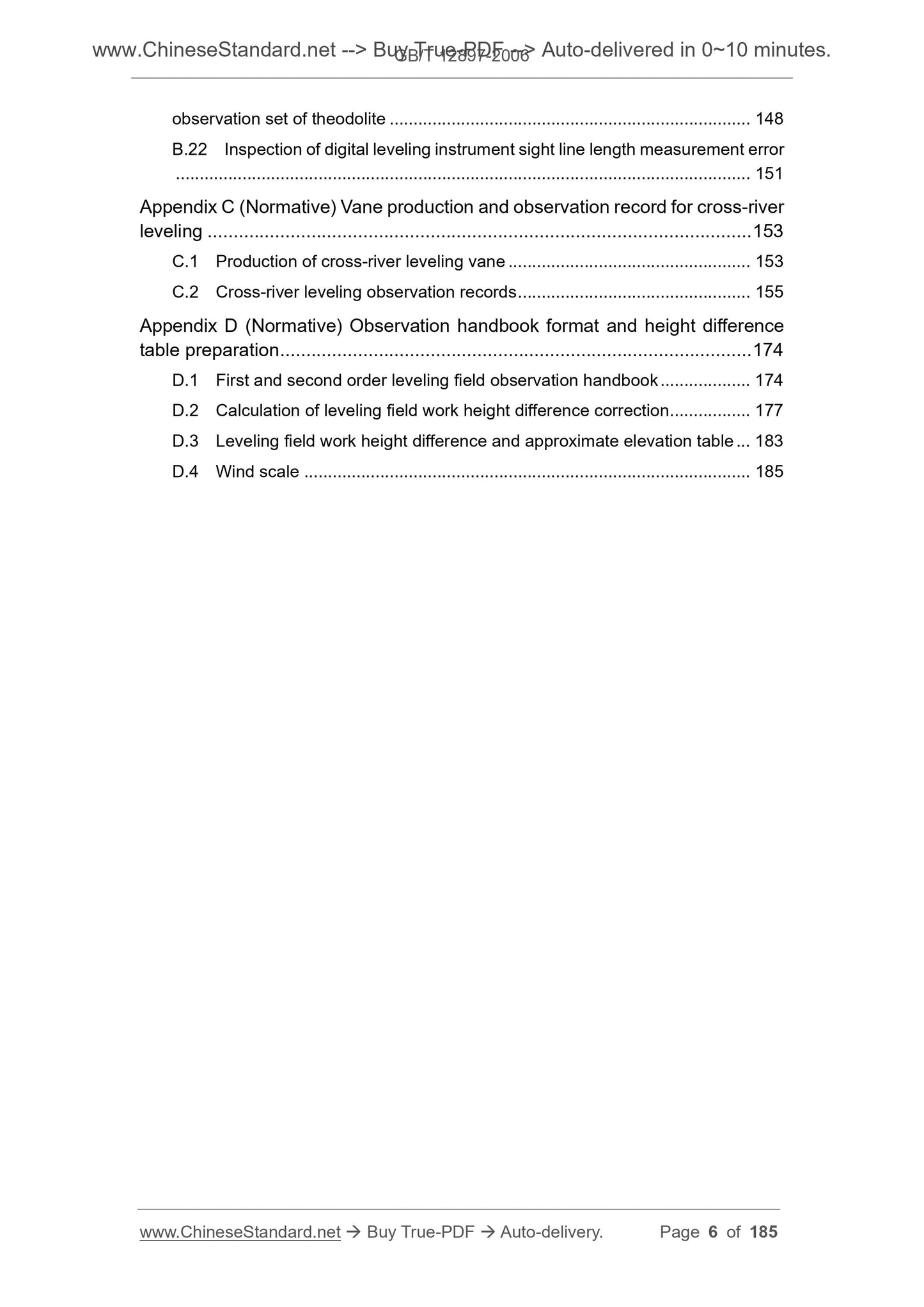
Appendix B (Normative) Instrument inspection method ... 100 
B.1 Visual inspection of leveling scale ... 100 
B.2 Calibration of circular level on leveling scale... 100 
B.3 Determination of division plane bending difference of leveling scale ... 100 
B.4 Determination of zero inequality difference and basic and auxiliary division
reading difference of a pair of scales ... 101 
B.5 Determination of verticality of leveling scale center axis and scale bottom
surface ... 104 
B.6 Visual inspection of leveling instrument ... 107 
B.7 Calibration of approximate leveler on leveling instrument ... 108 
B.8 Determination of lost motion and division values for leveling instrument
optical micrometer ... 109 
B.9 Determination of mean square error in level sight line observation ... 112 
B.10 Determination of automatic leveling instrument compensation error ... 116 
B.11 Calibration of leveling instrument reticule ... 121 
B.12 Determination of stadia constants for leveling instrument ... 121 
B.13 Determination of leveling instrument focusing lens run error ... 123 
B.14 Determination of transposition error of bubble level ... 128 
B.15 Calibration of leveling instrument i angle ... 129 
B.16 Determination of the swing difference 2C angle of double-position
automatic levelling instrument ... 131 
B.17 Determination of mean square error and vertical axis error of survey station
height difference observation by leveling instrument ... 133 
B.18 Determination of tilting screw lost motion, division error, and division value
of leveling instrument ... 136 
B.19 Determination of leveling instrument coincident leveler division value .. 140 
B.20 Determination of theodolite vertical dial micrometer run error ... 146 
B.21 Determination of mean square error in vertical angle observation in one
observation set of theodolite ... 148 
B.22 Inspection of digital leveling instrument sight line length measurement error
... 151 
Appendix C (Normative) Vane production and observation record for cross-river
leveling ... 153 
C.1 Production of cross-river leveling vane ... 153 
C.2 Cross-river leveling observation records ... 155 
Appendix D (Normative) Observation handbook format and height difference
table preparation ... 174 
D.1 First and second order leveling field observation handbook ... 174 
D.2 Calculation of leveling field work height difference correction ... 177 
D.3 Leveling field work height difference and approximate elevation table ... 183 
D.4 Wind scale ... 185 
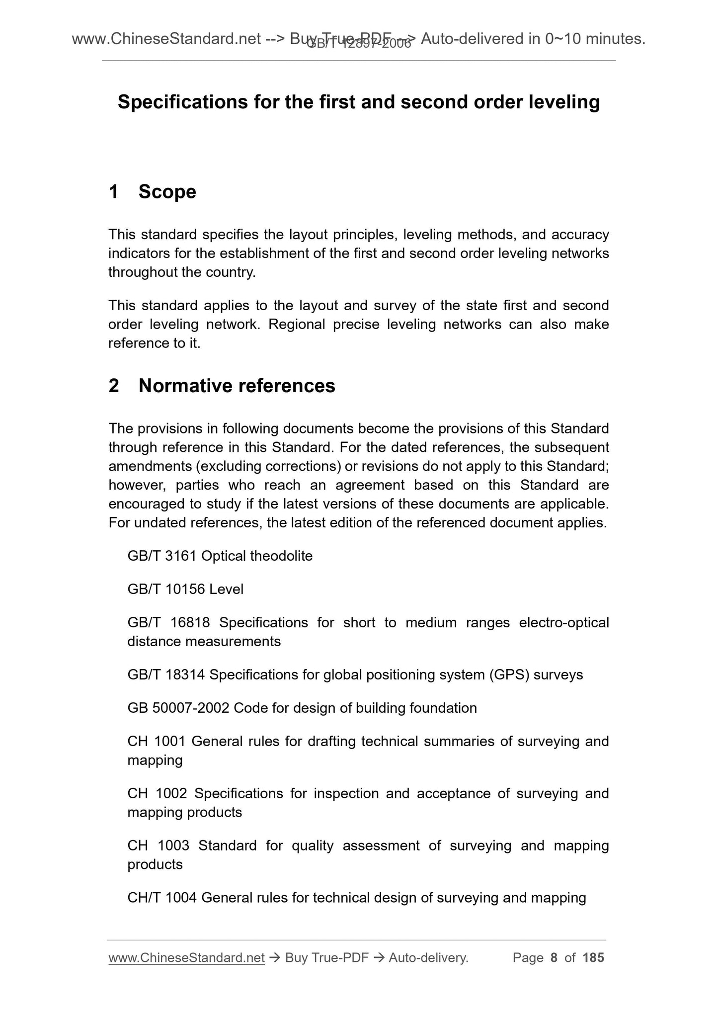
Specifications for the first and second order leveling
1 Scope
This standard specifies the layout principles, leveling methods, and accuracy
indicators for the establishment of the first and second order leveling networks
throughout the country.
This standard applies to the layout and survey of the state first and second
order leveling network. Regional precise leveling networks can also make
reference to it.
2 Normative references
The provisions in following documents become the provisions of this Standard
through reference in this Standard. For the dated references, the subsequent
amendments (excluding corrections) or revisions do not apply to this Standard;
however, parties who reach an agreement based on this Standard are
encouraged to study if the latest versions of these documents are applicable.
For undated references, the latest edition of the referenced document applies.
GB/T 3161 Optical theodolite
GB/T 10156 Level
GB/T 16818 Specifications for short to medium ranges electro-optical
distance measurements
GB/T 18314 Specifications for global positioning system (GPS) surveys
GB 50007-2002 Code for design of building foundation
CH 1001 General rules for drafting technical summaries of surveying and
mapping
CH 1002 Specifications for inspection and acceptance of surveying and
mapping products
CH 1003 Standard for quality assessment of surveying and mapping
products
CH/T 1004 General rules for technical design of surveying and mapping
CH/T 2004 The general rules of the electronic data recording for field
surveying
CH/T 2006 The electronic data recording rules for leveling
JJG 8 Specifications for leveling rule verification
JJG 414 Verification regulation of optical theodolite
JJG 425 Verification regulation of levels
JJG 703 Verification regulation of electro-optical distance meter (EDM
instruments)
JJF 1118 Calibration specification for global positioning system (GPS)
receiver
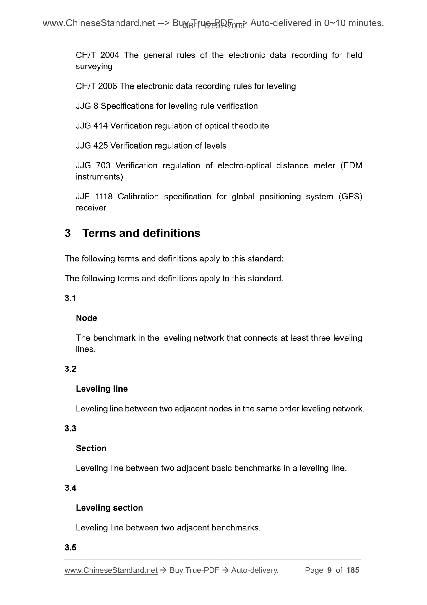
3 Terms and definitions
The following terms and definitions apply to this standard.
3.1
Node
The benchmark in the leveling network that connects at least three leveling
lines.
3.2
Leveling line
Leveling line between two adjacent nodes in the same order leveling network.
3.3
Section
Leveling line between two adjacent basic benchmarks in a leveling line.
3.4
Leveling section
Leveling line between two adjacent benchmarks.
3.5
f) Locations that may be destroyed or inconveniently observed due to
construction in the short term;
g) Filling sections of road.
5.1.3 Selection of bedrock benchmark
The bedrock benchmarks should be selected on the outcrop of the bedrock or
bedrock not deeper than 5 m above the ground. The selection of bedrock
benchmarks shall be attended by geologists, to collect and analyze existing
data, to make field survey to understand the geological structure, the nature of
rocks and soils, adverse geological phenomena and groundwater. If the existing
data does not meet the requirements, the necessary exploration shall be carried
out. After the selection of the bedrock benchmark, the geological survey report
shall be prepared point by point and submitted. The contents of the geological
survey report are as follows.
a) The geodetic coordinates, topography, geomorphology, geological
structure, adverse geologic phenomena, stratum formation condition,
physical and mechanical properties of rock and soil of the benchmark
positions;
b) The stability of foundation, uniformity of rock and soil and allowable
bearing capacity, depth of groundwater and extent of change, maximum
soil freezing depth and thawing depth, engineering geological hazards
that may occur after the setting of benchmarks, and construction
proposals;
c) The engineering geological profile within 50 m around the point and the
benchmark pit geodetic column map.
The preparation of the geological survey report shall be carried out in
accordance with the provisions of clause 3.0.3 of GB 50007-2002.
5.1.4 Work to be done after point selection
After each benchmark position is selected, a point mark with a noted number
and a mark stone type shall be set up. In accordance with the requirements of
A.3, it shall fill and draw the description of benchmark based on the format as
shown in Figure A.2. In the course of selecting the leveling line, the leveling line
map shall be drawn section by section in accordance with the requirements of
A.2. The pattern is shown in Figure A.1. For the nodes of the leveling network,
it shall fill the node connect leveling map in accordance with the requirements
of A.4 based on the format as shown in Figure A.3.
the culvert and is used to accommodate the lower mark. In the culvert,
pour concrete to the lower mark hole, place the lower mark, pour concrete
to the culvert top end, use vibrating bar to tamper it in layers to exhaust
he bottom gas. In the center of the culvert, a leveling mark shall be placed
at the center of the culvert. Place the leveling mark at the center of the
culvert top, which shall be upright, straight, and head to north, smoothen
the concrete top surface. After the initial setting of the concrete, add the
mark protective cover and cementer protective cover (inside of the iron
protective cover shall be coated with butter), make external decoration.
The burial specification and shape are as shown in Figure A.9.
5.2.4.2 Burial of rock stratum leveling mark stone
For the burial of basic leveling mark stone or common leveling mark stone on
the outcrop rock stratum, it shall remove the surface weathering material, drill
a hole with a depth of not less than 0.15 m and an opening diameter of not less
than 0.2 m on the hard rock plane, clean the hole, pour concrete to embed the
lev...
View full details