1
/
of
5
PayPal, credit cards. Download editable-PDF and invoice in 1 second!
GB/T 12606-2016 English PDF (GB/T12606-2016)
Regular price
$90.00
Regular price
Sale price
$90.00
Unit price
/
per
Shipping calculated at checkout.
Couldn't load pickup availability
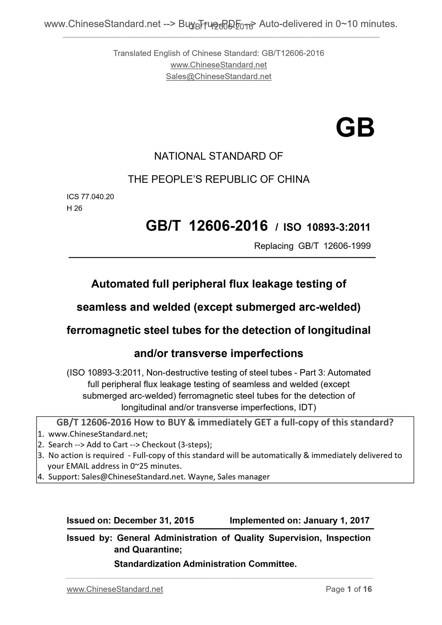
GB/T 12606-2016: Automated full peripheral flux leakage testing of seamless and welded (except submerged arc-welded) ferromagnetic steel tubes for the detection of longitudinal and/or transverse imperfections
Delivery: 9 seconds. Download (& Email) true-PDF + Invoice.
Get Quotation: Click GB/T 12606-2016 (Self-service in 1-minute)
Historical versions (Master-website): GB/T 12606-2016
Preview True-PDF (Reload/Scroll-down if blank)
>GB/T 12606-2016
Automated full peripheral flux leakage testing of seamless and welded (except submerged arc-welded) ferromagnetic steel tubes for the detection of longitudinal and/or transverse imperfections
ICS 77.040.20
H26
National Standards of People's Republic of China
Replacing GB/T 12606-1999
Seamless and welded (except submerged arc) ferromagnetic steel
Full-circle longitudinal and/or transverse magnetic flux leakage testing imperfections automatic
(Exceptsubmergedarc-welded) ferromagneticsteeltubesforthe
(ISO 10893-3.2011, Non-destructivetestingofsteeltubes-Part 3.
welded (exceptsubmergedarc-welded) ferromagneticsteeltubesforthe
detectionoflongitudinaland/ortransverseimperfections, IDT)
Published 2017-07-01 2016-08-29 implementation
Administration of Quality Supervision, Inspection and Quarantine of People's Republic of China
Standardization Administration of China issued
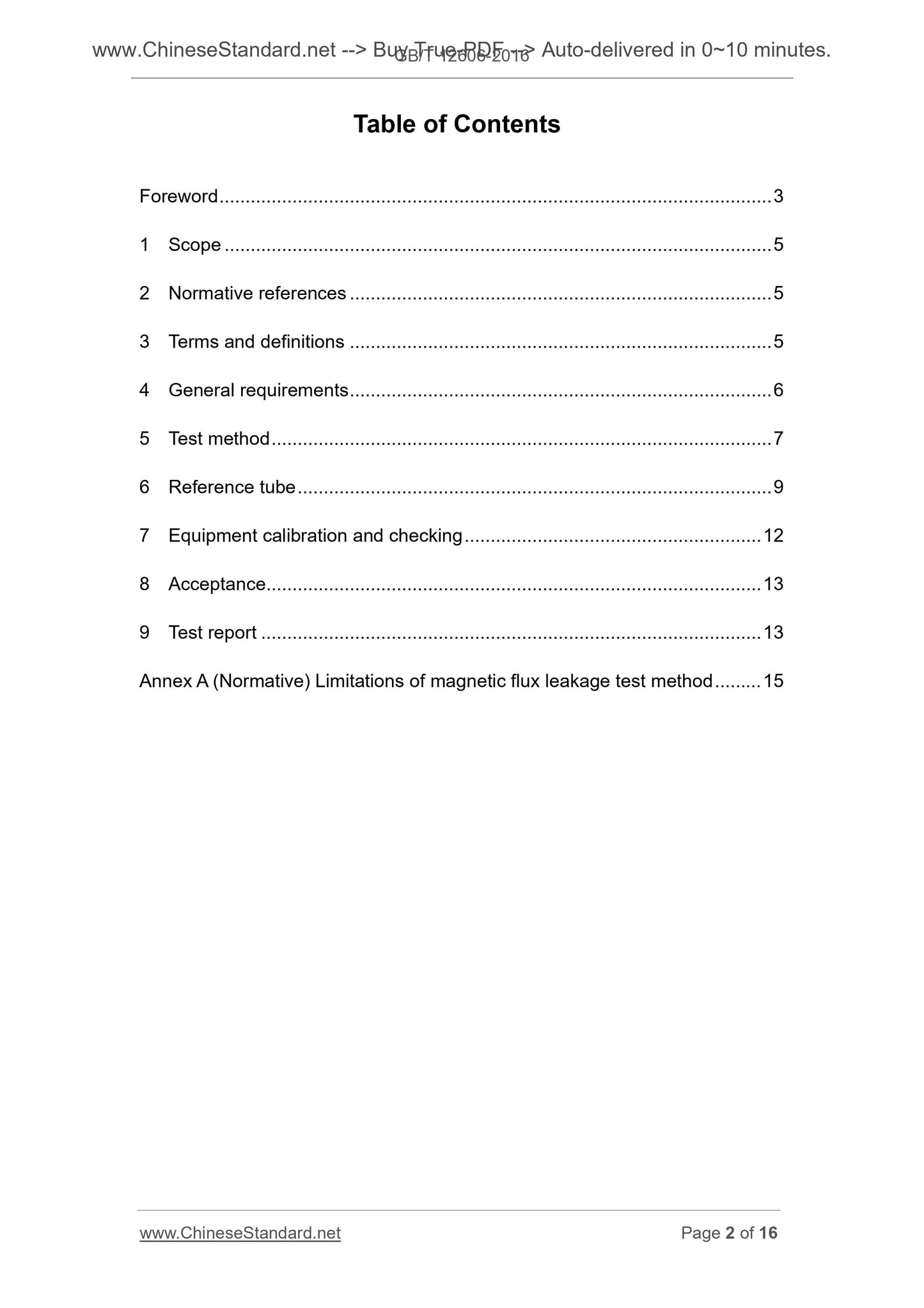
Table of Contents
Preface Ⅰ
1 Scope 1
2 Normative References 1
Terms and definitions 1 3
4 General requirements 2
5 Detection Method 2
Comparative 4 sample tube 6
7 equipment calibration and verification 6
8 acceptance 6
9 Test Report 6
Limitations (normative) method for detecting magnetic leakage Appendix A 7
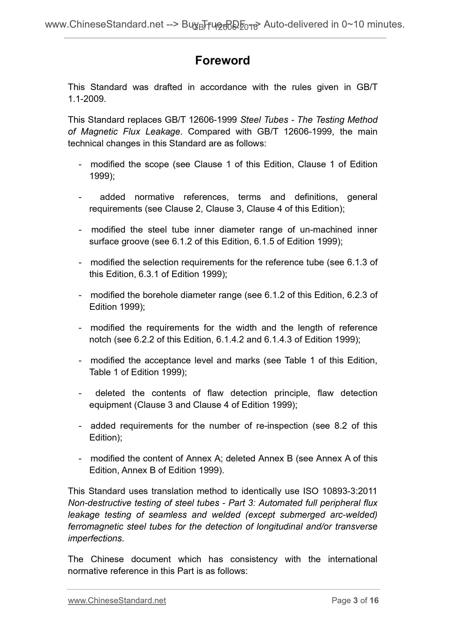
Foreword
This standard was drafted in accordance with rules GB/T 1.1-2009 given.
Instead of the standard GB/T 12606-1999 "steel flux leakage testing method", compared with the GB/T 12606-1999, Technical change
as follows.
--- modify the scope of the standard (see Chapter 1, 1999 edition of the Chapter 1);
--- increase the content of normative references, terms and definitions, the general requirements (see Chapter 2, Chapter 3, Chapter 4);
--- not modify the processing of the inner surface of the inner diameter of pipe groove range (see 612, 1999 edition 6.1.5.);
--- modify the contrast material selection requirements like tubes (see 613, 1999 edition of 6.3.1.);
--- modify the pore size range of drilling (see 612, 1999 edition of 6.2.3.);
--- modify requirements groove width and length (see 622, 1999 edition of 6.1.4.2 and 6.1.4.3..);
--- modify the acceptance level and logo (see Table 1, Table 1 of the 1999 edition);
--- delete the contents of the principle of testing, testing equipment (Chapters 3 and 4 of the 1999 edition);
--- increase the requirements for the number of re-testing (see 8.2);
--- modify the contents of Appendix A, deleted Annex B (see Appendix A, 1999 edition of Appendix B).
This translation method using identical with standard ISO 10893-3.2011 "NDT steel Part 3. seamless and welded (SAW
Excluded) ferromagnetic steel longitudinal and/or transverse imperfections Automatic full peripheral flux leakage testing. "
Consistency correspondence relationship with the international standard in normative documents referenced in our files are as follows.
--- GB/T 9445-2008 NDT personnel qualification and certification (ISO 9712.2005, IDT)
The standard proposed by China Iron and Steel Association.
This standard by the National Steel Standardization Technical Committee (SAC/TC183).
This standard was drafted. Tianjin Pipe Group Co., Ltd., Hengyang Valin Steel Tube Co., Ltd., Metallurgical Industry Information Standards Institute.
The main drafters. Zhao Renshun, An Jianbo, Zhao Bin, Dong Li, Zhang Li.
This standard supersedes the previous editions are.
--- GB/T 12606-1999.
Seamless and welded (except submerged arc) ferromagnetic steel
Full-circle longitudinal and/or transverse magnetic flux leakage testing imperfections automatic
1 Scope
This standard specifies the seamless and welded (except submerged arc) the whole circumference of ferromagnetic steel automatic defect detecting magnetic leakage requirements.
Unless otherwise specified in the purchase order, this standard is mainly used for the detection of longitudinal imperfections.
This standard is suitable for detecting an outer diameter of 10mm is greater than or equal to steel.
This standard is also applicable to the detection of the hollow profile.
2 Normative references
The following documents for the application of this document is essential. For dated references, only the edition cited applies this
file. For undated references, the latest edition (including any amendments) applies to this document.
ISO 9712 NDT personnel qualification and certification (Non-destructivetesting-Qualificationandcertifica-
tionofNDTpersonnel)
NDT ISO 11484 owner of the steel product qualification system [Steelproducts-Employers qualification
systemfornon-destructivetesting (NDT) personnel]
3 Terms and Definitions
Defined in ISO 11484 and the following terms and definitions apply to this document.
3.1
Standard contrast defect referencestandard
Artificial defect nondestructive testing apparatus (such as drilling, grooves and dents) for verification.
3.2
Comparative sample tube referencetube
Comparison to a standard steel contains defects or pipe section.
3.3
Comparative sample referencesample
Comparison of standard samples containing defects (e.g., pipe, sheet or strip).
NOTE. This standard uses only the term "control sample tubes", also includes the term "comparative sample."
3.4
Tube tube
Any cross-sectional shape of the opening ends of the hollow elongated products.
3.5
Seamless seamlesstube
The solid product obtained a perforated hollow tube, and then by hot working or cold working to obtain the final dimensions.
3.6
Pipe weldedtube
By welding adjacent edges of the flat rolled together to make a tube, after welding can be performed hot or cold working, to give a final
size.
3.7
Manufacturers manufacturer
Products manufactured in accordance with relevant standards and statements delivered products meet the relevant standards applicable to all organizations in terms of requirements.
3.8
Protocol agreement
At the time of inquiry and order, the contract between the manufacturer and the purchaser.
4 General requirements
4.1 Unless standards or purchaser and manufacturer agreed, full peripheral magnetic leakage detection to be operating in all the major steel production processes
(Rolling, heat treatment, cold and hot processing, sizing and straightening the primary and the like) after completion of all of.
4.2 detected steel pipe should have enough flatness to ensure the effectiveness of detection. The surface should not affect detection reliability of foreign bodies.
4.3 Detection shall be according to ISO 9712, ISO 11484 or equivalent standard trained and qualified operator appointed by the manufacturer are eligible
Carried out under the supervision of staff. In the case of testing by a third party, this shall be the purchaser agreed to consult with the manufacturer.
The employer shall file a certificate issued by the authority to operate. NDT3 a non-destructive testing (NDT) operators shall be approved by the Employer
Authorized officers.
Note. The definition of the 1, 2 and 3 can be found in the corresponding international standards such as ISO 9712 and ISO 11484.
5 Detection
5.1 using a longitudinal magnetic flux leakage by detection of imperfections pipe (see FIG. 1), and/or lateral defect detected by mutual agreement (see FIG. 2). This standard
No registration predetermined wall thickness limits, given the limitations described in Appendix A of the detection method.
Pipe ends have a short length can not be detected any undetected tube end should be carried out in accordance with the requirements of the product standards of the respective
Line processing.
5.2 In the detection process, steel pipe and a sensor motion relative to each other due to scanning the entire surface of the steel pipe. Relative detection process
Velocity variations are not to exceed ± 10%.
5.3 the maximum width of each sensor is parallel to the main axis for detecting defects should be 30mm.
5.4 automatic equipment should trigger an alarm level of binding of the labeled and/or separation system into the steel-defective products or suspicious.
a) rotating magnetic flux leakage sensor technology advances straight steel --- b) fixing the magnetic flux leakage sensor coil steel technology advances ---
Description.
1 --- magnetic flux leakage sensor;
2 --- steel;
N --- Arctic;
S --- South Pole.
a rotational direction of the probe.
Pipe rotation direction b.
1 a schematic longitudinal cutaway magnetic flux leakage inspection
Description.
1 --- staggered array sensor;
2 --- Power (DC).
NOTE. MFL sensor may take many forms, for example. the absolute and differential modes, depending on the equipment used and other factors. In addition to this method of FIG display,
Other methods of magnetic flux is parallel to the pipe axis may also be employed.
FIG 2 a schematic transverse magnetic flux leakage inspection imperfections
Comparative sample tube 6
6.1 General
6.1.1 Comparison calibration standard defect for nondestructive testing equipment. These standard dimensions should not be considered defects such devices can be detected
The minimum size of the defect.
Each probe 6.1.2 magnetic flux leakage testing apparatus should be used in comparative sample tube outer face, the outer face of the groove than the groove ratio be verified or inside.
Purchaser also be agreed with the manufacturer, the control sample using a radial through-hole tube calibration equipment. In this case, it should be a specific test
Maximum pore received level agreement, and the manufacturer should be able to justify the use of the aperture device disposed corresponding to detection sensitivity and usage rule
The outer face of a given depth than the comparative sensitivity of the inner surface of the groove and the groove depth of the obtained protocol.
Note. The use of defined pore size steel according to standards or other relevant factors. Typical pore size in the range of 0.80mm ~ 3.20mm.
Before the comparison processing tank surface, the inner surface of the comparative sample tube may be grinding or machining. When the inner diameter steel pipe to make not less than 20mm
Inner surface of the groove, the manufacturer unless otherwise agree available, or while the pipe wall thickness is greater than 20mm, but due to the technology described in Appendix A
Limit, even with the maximum rate in Table A.1, the detection of the inner surface of the steel pipe is not sufficient.
6.1.3 Comparison sample tube and the subject steel should have the same nominal diameter and wall thickness, the surface state and the same delivery conditions (e.g., as-rolled condition, n
Fire, quenching and tempering) and similar grade (grade). Said the thickness of more than 10mm, if the groove depth of the subject is based on the nominal pipe wall
Thick calculated, comparison may be greater than the wall thickness of the tube-like male subject said steel pipe wall thickness. If required, the manufacturer should be able to prove their method of
Effectiveness.
6.1.4 should be separated from each other between the outer surface of the groove and the inner surface of the groove and the through holes may be used with the control sample, and the tube end portions thereof to each other (when the same
When using the inner and outer grooves comparison), so as to obtain a display signal legible.
6.2 groove Comparison
6.2.1 General
a) Comparative groove should be "N" shaped groove (see FIG. 3), and should be parallel to the main pipe; purchaser when the manufacturer agreed detects lateral missing
When less Comparative steel shaft should be perpendicular to the slot (see FIG. 4);
Nominally both sides b) should be parallel grooves, and groove bottom sides should be nominally at right angles;
c) Comparative grooves should be machined, spark erosion or other production methods.
NOTE. The bottom corner or a groove may be arcuate.
Description.
--- width W;
d --- depth.
FIG 3 "N" shaped grooves
a) an outer partial surface of the circumferential groove b) the inner surface of the partial circumferential groove
Description.
d --- depth.
FIG 4 allows the shape of transverse grooves
6.2.2 Comparison of the size of the slot
a) a width, w (see FIG. 3)
Comparative groove width should be 1mm or less in its depth, of whichever is greater.
b) the depth, d (see FIG. 3 and FIG. 4)
The appearance of the face than the depth of the groove to comply with Table 1, and meet the following requirements.
--- minimum groove depth. acceptance level for F2 and F3 is 0.30mm; acceptance level for F4 and F5 is 0.50mm;
--- maximum groove depth. 1.5mm.
The inner surface of the groove depth should be subject to the purchaser with the manufacturer protocol (see Appendix A), but not less than the predetermined depth of the outer surface of the groove is greater than or
Maximum ratio given in Table A.1. The maximum depth of the inner surface of the groove should be 3.0mm.
The groove depth should allow tolerance of ± 15% for the deep groove.
c) length
Unless otherwise specified standard product manufacturer or purchaser agreed slot length should be greater than the width of each sensor. In any case
Under conditions slot length should not exceed 50mm.
If the detected lateral imperfections, the minimum length of the circumferential groove (see FIG. 4) shall be 25mm.
Table 1 acceptance level and the corresponding outer surface of the groove depth
Acceptance levels groove depth is a percentage of the nominal wall thickness
F2 5 (minimum 0.30mm)%
F3 10% (minimum 0.30mm)
F4 12.5 (minimum 0.50mm)%
F5 15 (minimum 0.50mm)%
Note. In all relates to nondestructive testing of standard steel, it is the same for a predetermined groove depth value corresponding to a different category in this table acceptance level. Although
Than the standard defects are the same, but a variety of detection methods may have different test results. Therefore, acceptance level prefix F (MFL) to avoid
Free direct equivalent other detection methods.
6.2.3 Comparison of defect verification standard
Comparative groove size and shape should be verified by appropriate technologies.
7 equipment calibration and verification
7.1 Comparison standard shall be verified at each detection cycle starts, the device to produce a clear consistent defect signal recog...
Share