Skip to product information
1 of 12

Sales@ChineseStandard.net (Field Test Asia Pte. Ltd.)

GB/T 12572-2008 English PDF (GBT12572-2008)

GB/T 12572-2008 English PDF (GBT12572-2008)

Regular price $405.00 USD
Regular price Sale price $405.00 USD
Sale Sold out
Shipping calculated at checkout.
Delivery: 3 seconds. Download true-PDF + Invoice.
Get QUOTATION in 1-minute: Click GB/T 12572-2008
Historical versions: GB/T 12572-2008
Preview True-PDF (Reload/Scroll if blank)

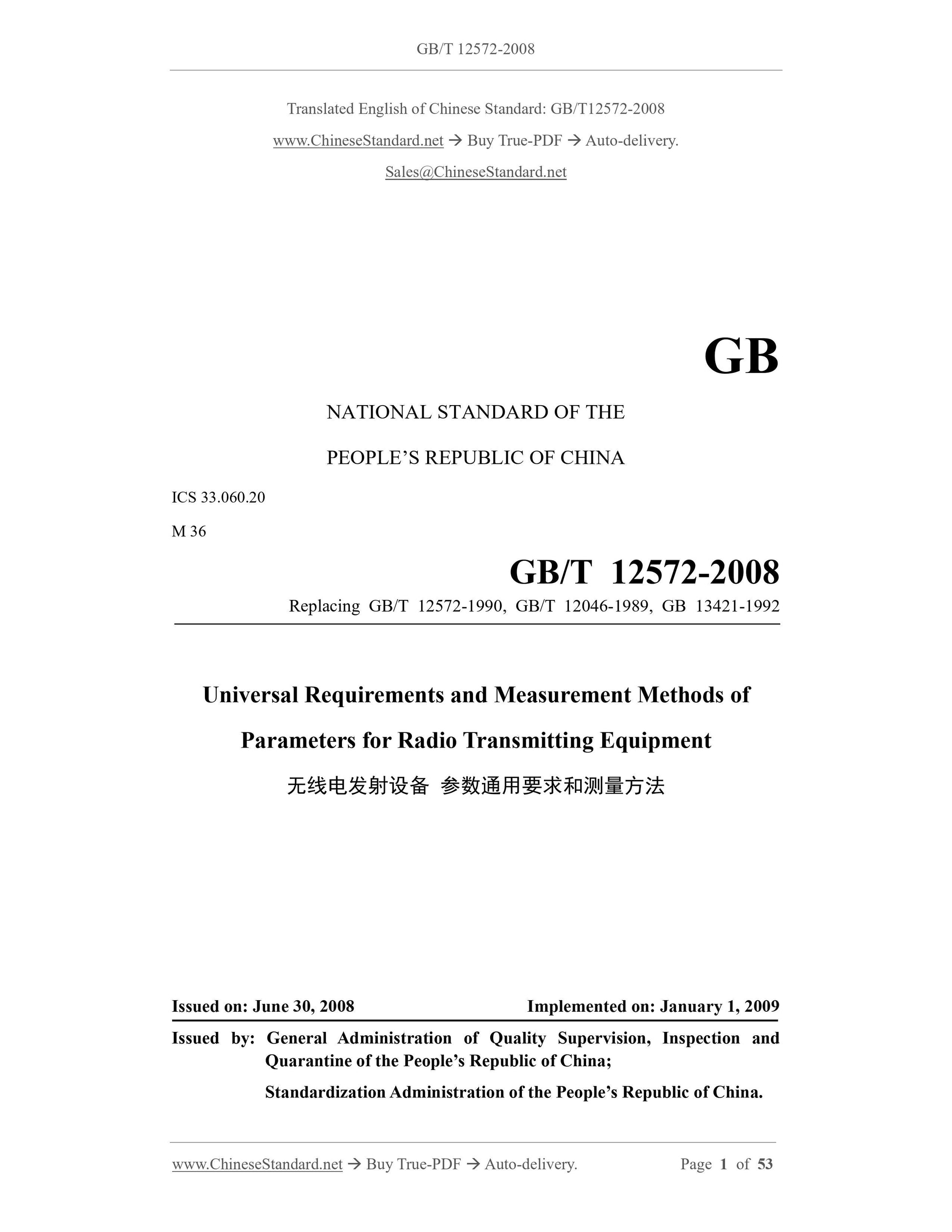
GB/T 12572-2008: Universal requirements and measurement methods of parameters for radio transmitting equipment
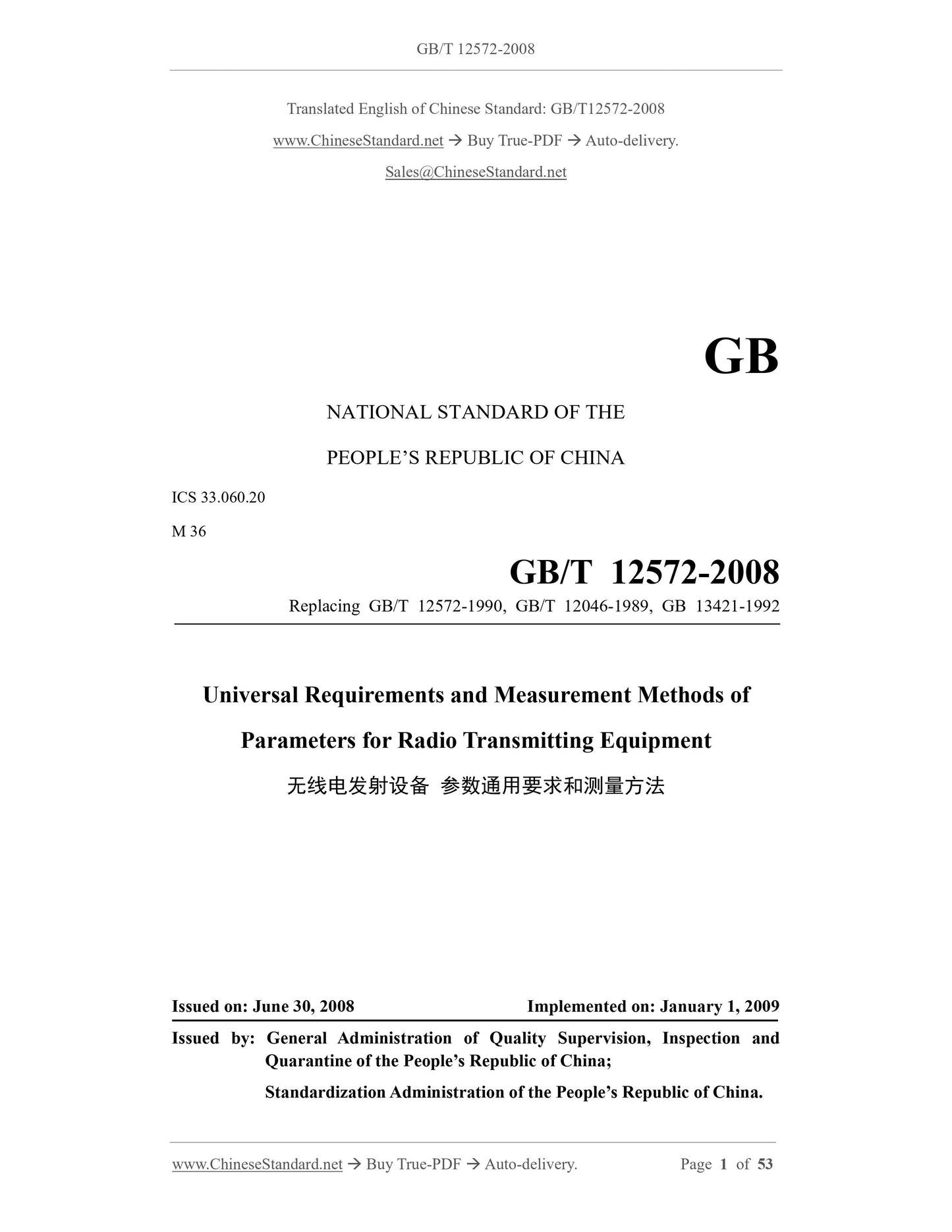
GB/T 12572-2008
GB
NATIONAL STANDARD OF THE
PEOPLE’S REPUBLIC OF CHINA
ICS 33.060.20
M 36
Replacing GB/T 12572-1990, GB/T 12046-1989, GB 13421-1992
Universal Requirements and Measurement Methods of
Parameters for Radio Transmitting Equipment
ISSUED ON: JUNE 30, 2008
IMPLEMENTED ON: JANUARY 1, 2009
Issued by: General Administration of Quality Supervision, Inspection and
Quarantine of the People’s Republic of China;
Standardization Administration of the People’s Republic of China.
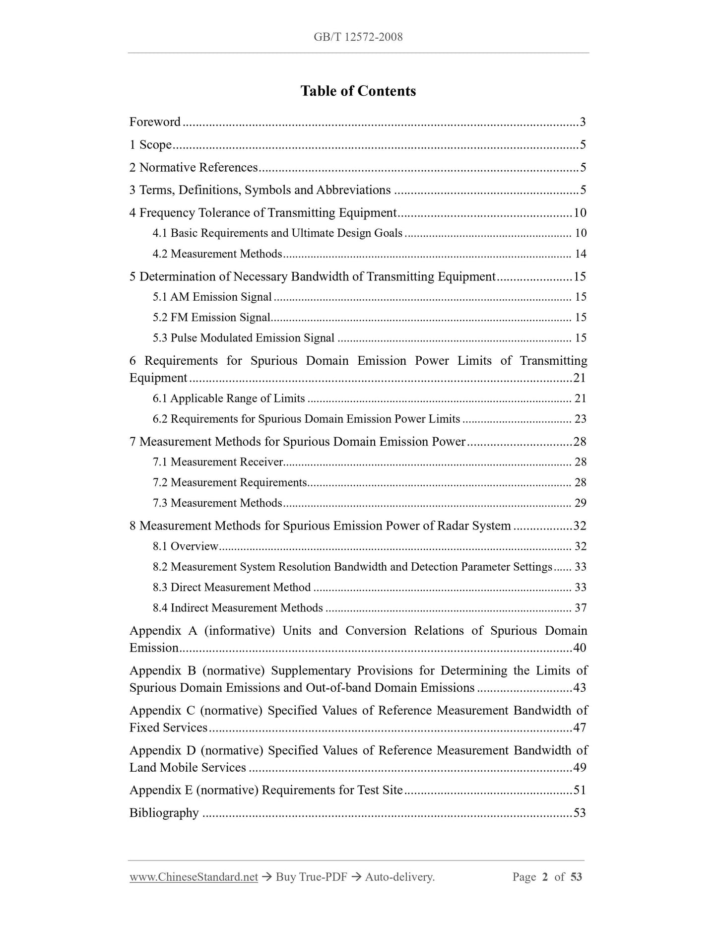
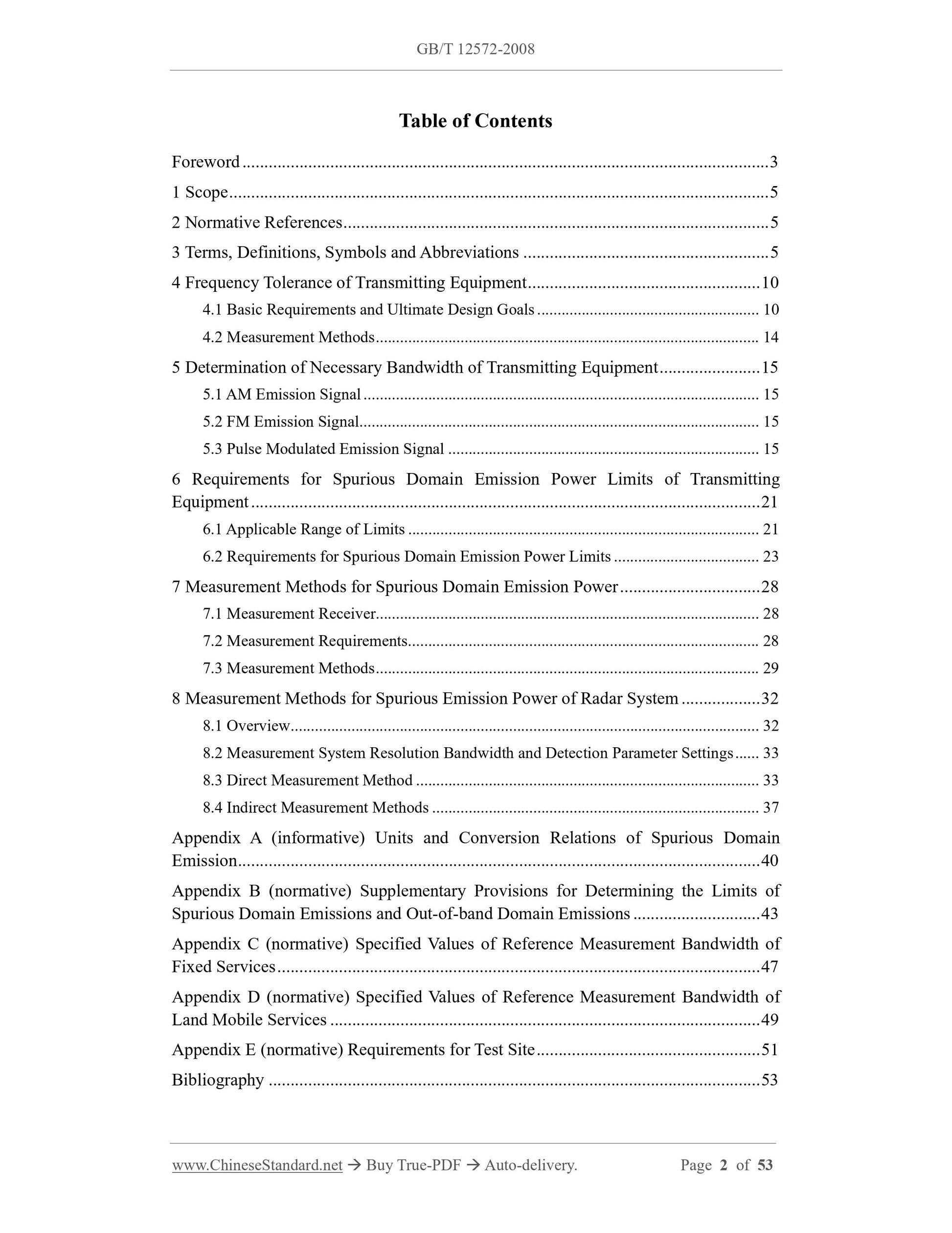
Table of Contents
Foreword ... 3
1 Scope ... 5
2 Normative References ... 5
3 Terms, Definitions, Symbols and Abbreviations ... 5
4 Frequency Tolerance of Transmitting Equipment ... 10
4.1 Basic Requirements and Ultimate Design Goals ... 10
4.2 Measurement Methods ... 14
5 Determination of Necessary Bandwidth of Transmitting Equipment ... 15
5.1 AM Emission Signal ... 15
5.2 FM Emission Signal ... 15
5.3 Pulse Modulated Emission Signal ... 15
6 Requirements for Spurious Domain Emission Power Limits of Transmitting
Equipment ... 21
6.1 Applicable Range of Limits ... 21
6.2 Requirements for Spurious Domain Emission Power Limits ... 23
7 Measurement Methods for Spurious Domain Emission Power ... 28
7.1 Measurement Receiver... 28
7.2 Measurement Requirements ... 28
7.3 Measurement Methods ... 29
8 Measurement Methods for Spurious Emission Power of Radar System ... 32
8.1 Overview ... 32
8.2 Measurement System Resolution Bandwidth and Detection Parameter Settings ... 33
8.3 Direct Measurement Method ... 33
8.4 Indirect Measurement Methods ... 37
Appendix A (informative) Units and Conversion Relations of Spurious Domain
Emission ... 40
Appendix B (normative) Supplementary Provisions for Determining the Limits of
Spurious Domain Emissions and Out-of-band Domain Emissions ... 43
Appendix C (normative) Specified Values of Reference Measurement Bandwidth of
Fixed Services ... 47
Appendix D (normative) Specified Values of Reference Measurement Bandwidth of
Land Mobile Services ... 49
Appendix E (normative) Requirements for Test Site ... 51
Bibliography ... 53
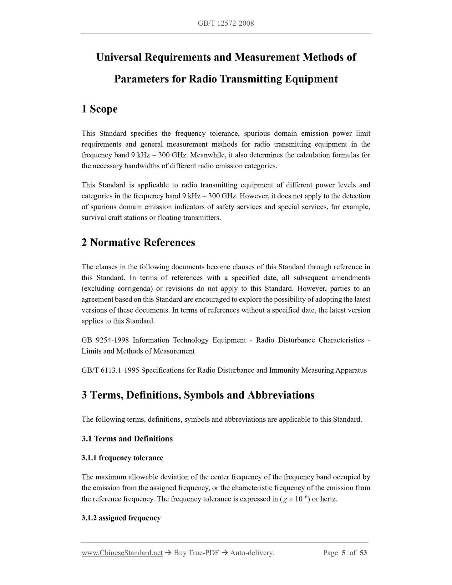
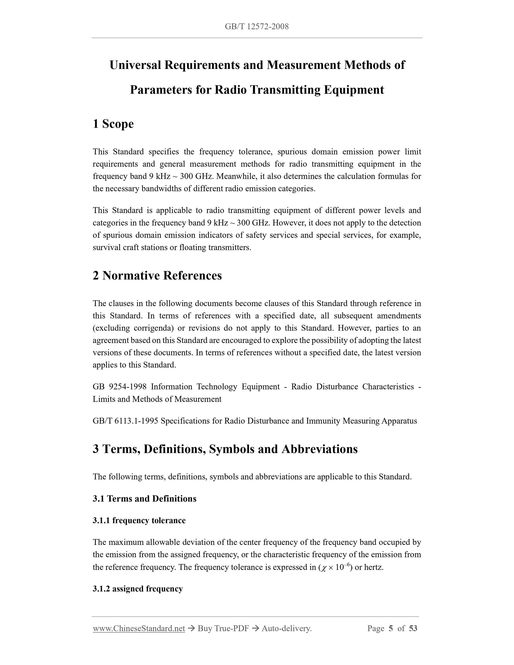
Universal Requirements and Measurement Methods of
Parameters for Radio Transmitting Equipment
1 Scope
This Standard specifies the frequency tolerance, spurious domain emission power limit
requirements and general measurement methods for radio transmitting equipment in the
frequency band 9 kHz ~ 300 GHz. Meanwhile, it also determines the calculation formulas for
the necessary bandwidths of different radio emission categories.
This Standard is applicable to radio transmitting equipment of different power levels and
categories in the frequency band 9 kHz ~ 300 GHz. However, it does not apply to the detection
of spurious domain emission indicators of safety services and special services, for example,
survival craft stations or floating transmitters.
2 Normative References
The clauses in the following documents become clauses of this Standard through reference in
this Standard. In terms of references with a specified date, all subsequent amendments
(excluding corrigenda) or revisions do not apply to this Standard. However, parties to an
agreement based on this Standard are encouraged to explore the possibility of adopting the latest
versions of these documents. In terms of references without a specified date, the latest version
applies to this Standard.
GB 9254-1998 Information Technology Equipment - Radio Disturbance Characteristics -
Limits and Methods of Measurement
GB/T 6113.1-1995 Specifications for Radio Disturbance and Immunity Measuring Apparatus
3 Terms, Definitions, Symbols and Abbreviations
The following terms, definitions, symbols and abbreviations are applicable to this Standard.
3.1 Terms and Definitions
3.1.1 frequency tolerance
The maximum allowable deviation of the center frequency of the frequency band occupied by
the emission from the assigned frequency, or the characteristic frequency of the emission from
the reference frequency. The frequency tolerance is expressed in (  106) or hertz.
3.1.2 assigned frequency
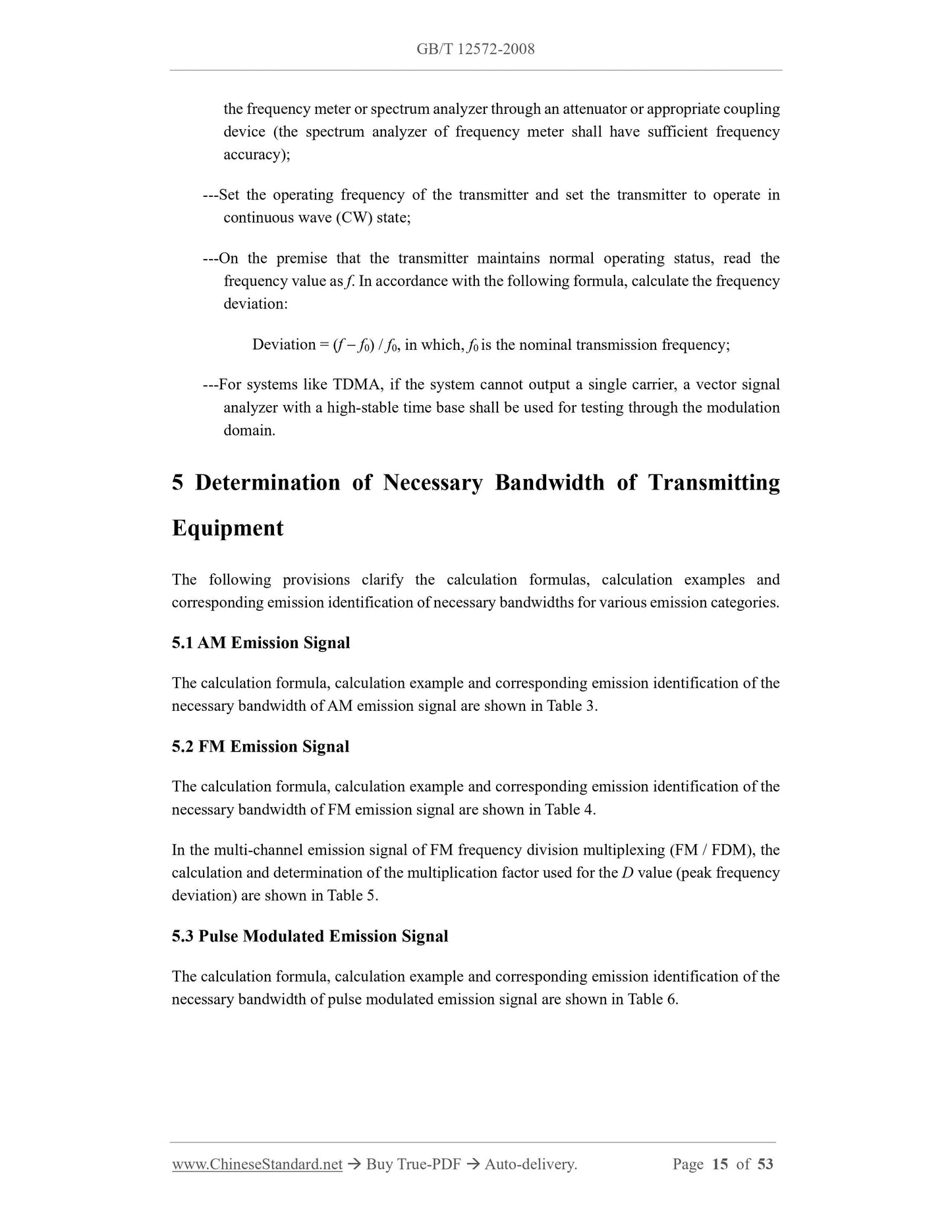
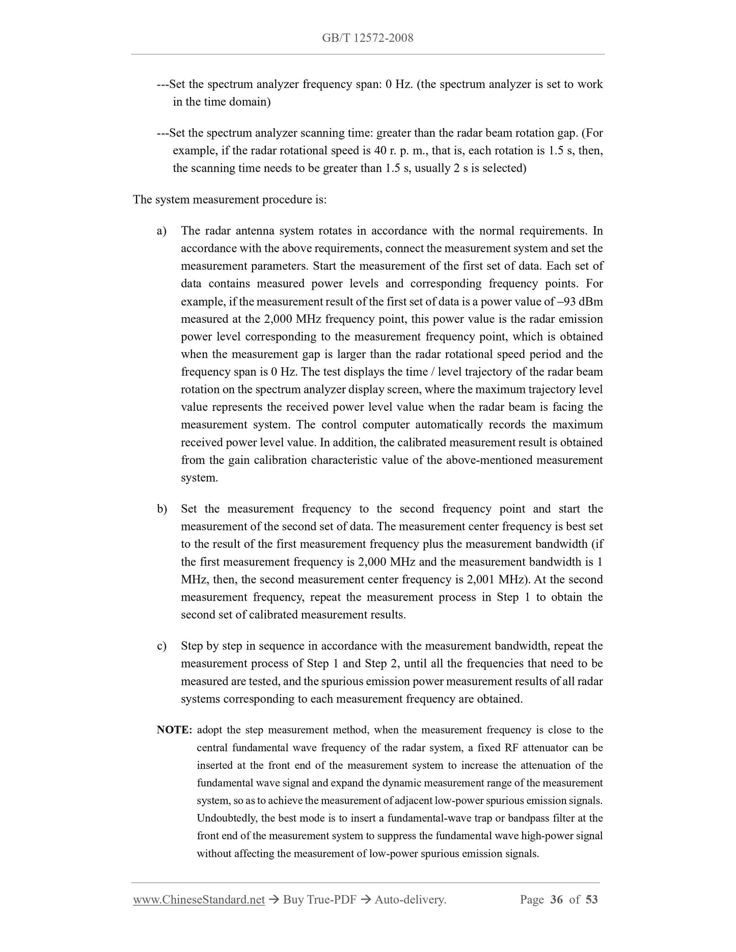
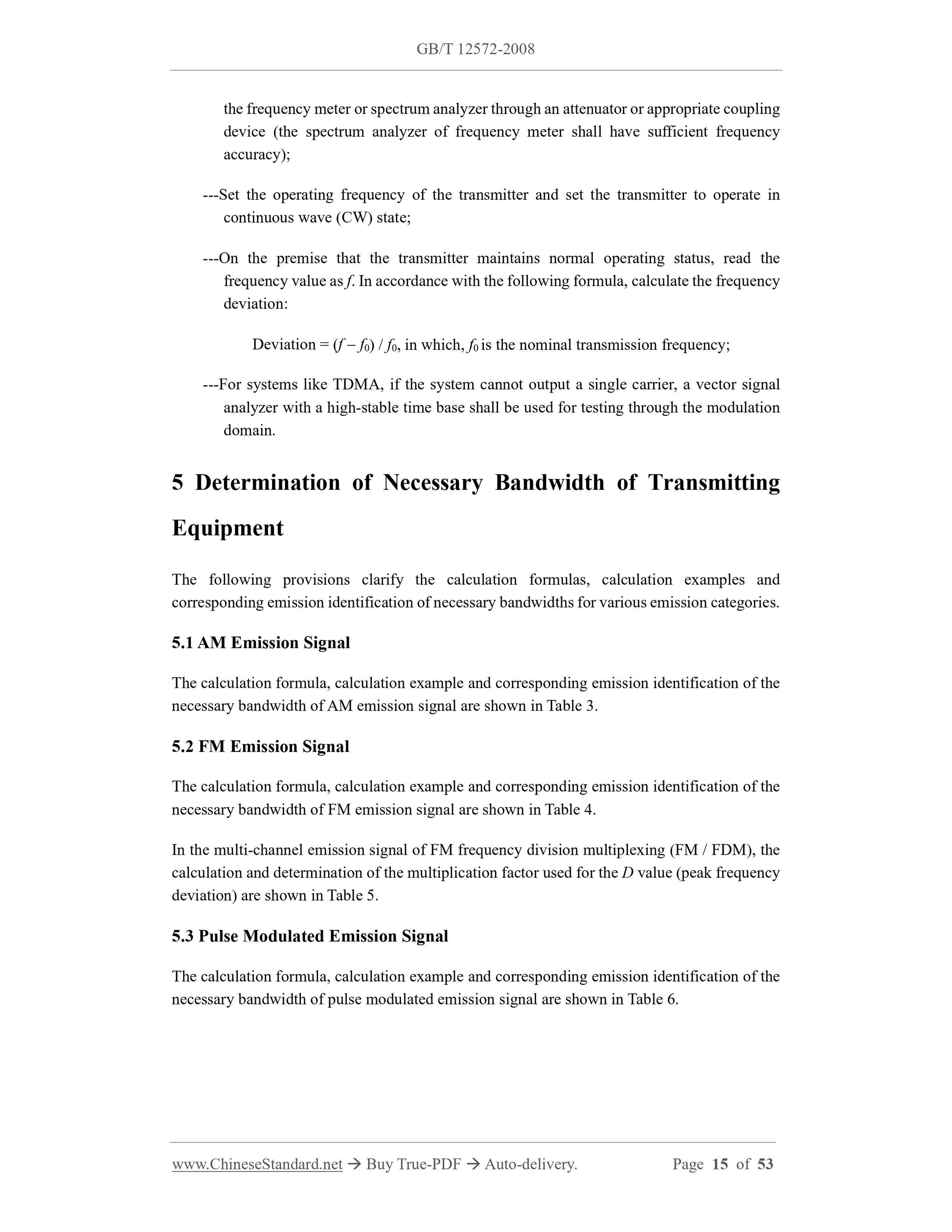
the frequency meter or spectrum analyzer through an attenuator or appropriate coupling
device (the spectrum analyzer of frequency meter shall have sufficient frequency
accuracy);
---Set the operating frequency of the transmitter and set the transmitter to operate in
continuous wave (CW) state;
---On the premise that the transmitter maintains normal operating status, read the
frequency value as f. In accordance with the following formula, calculate the frequency
deviation:
Deviation = (f  f0) / f0, in which, f0 is the nominal transmission frequency;
---For systems like TDMA, if the system cannot output a single carrier, a vector signal
analyzer with a high-stable time base shall be used for testing through the modulation
domain.
5 Determination of Necessary Bandwidth of Transmitting
Equipment
The following provisions clarify the calculation formulas, calculation examples and
corresponding emission identification of necessary bandwidths for various emission categories.
5.1 AM Emission Signal
The calculation formula, calculation example and corresponding emission identification of the
necessary bandwidth of AM emission signal are shown in Table 3.
5.2 FM Emission Signal
The calculation formula, calculation example and corresponding emission identification of the
necessary bandwidth of FM emission signal are shown in Table 4.
In the multi-channel emission signal of FM frequency division multiplexing (FM / FDM), the
calculation and determination of the multiplication factor used for the D value (peak frequency
deviation) are shown in Table 5.
5.3 Pulse Modulated Emission Signal
The calculation formula, calculation example and corresponding emission identification of the
necessary bandwidth of pulse modulated emission signal are shown in Table 6.
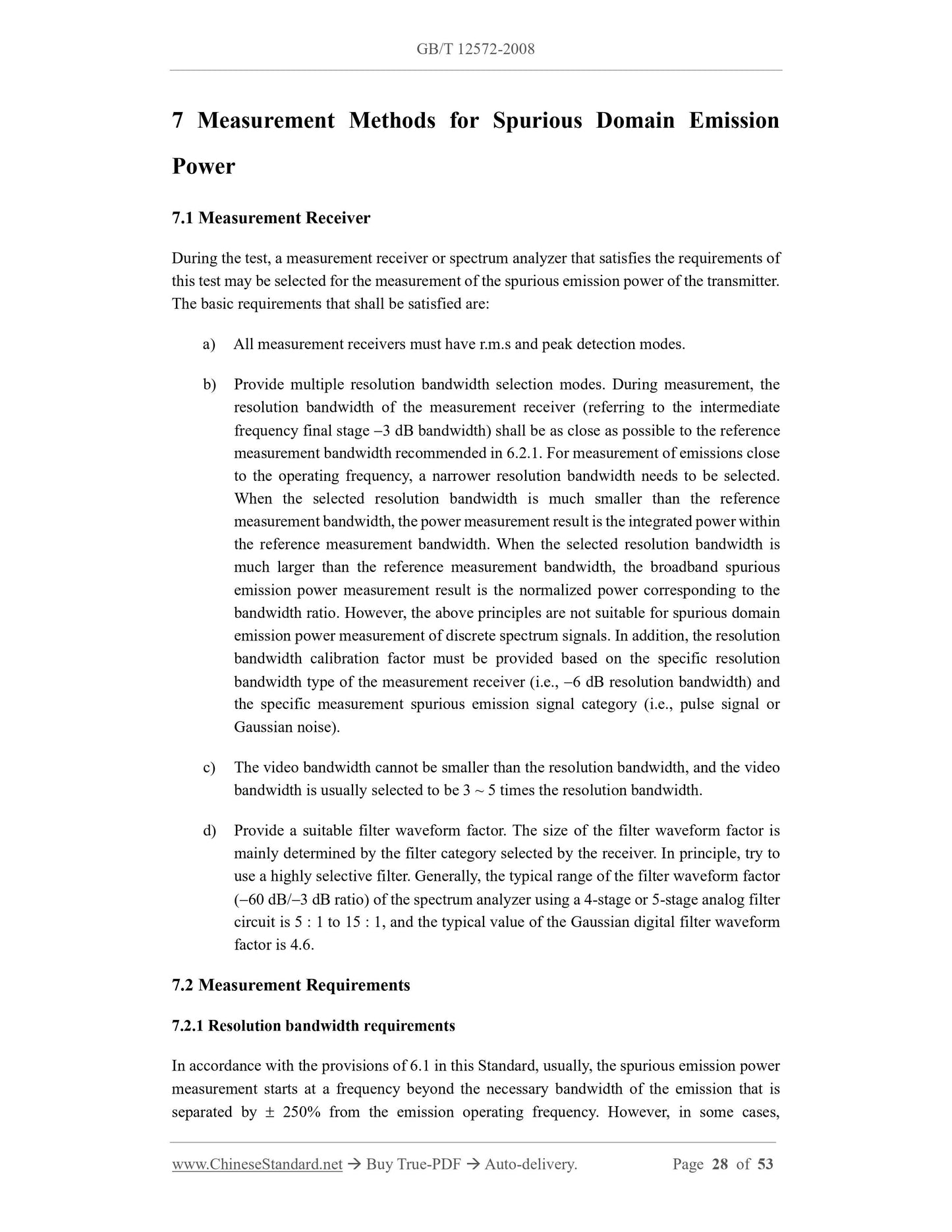
7 Measurement Methods for Spurious Domain Emission
Power
7.1 Measurement Receiver
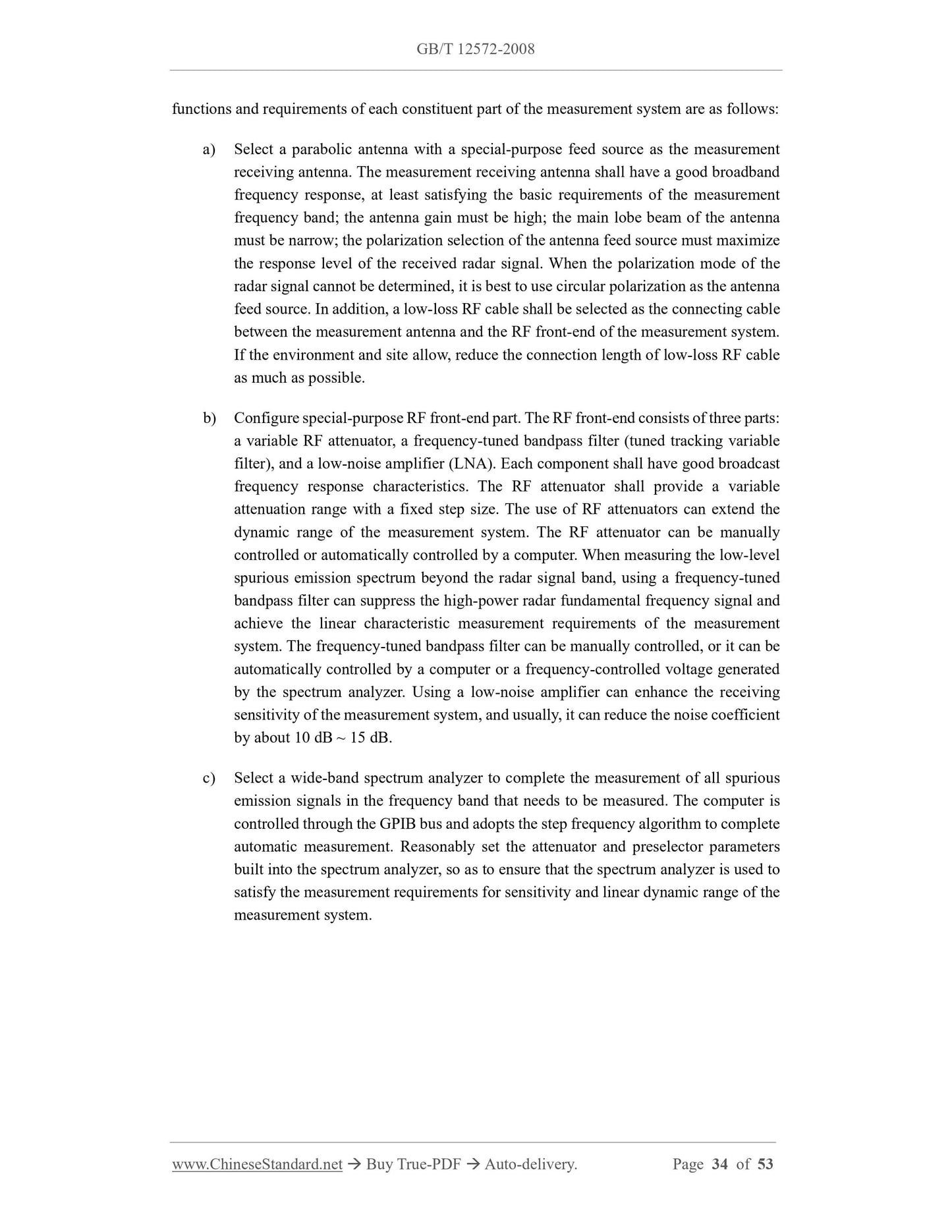
During the test, a measurement receiver or spectrum analyzer that satisfies the requirements of
this test may be selected for the measurement of the spurious emission power of the transmitter.
The basic requirements that shall be satisfied are:
a) All measurement receivers must have r.m.s and peak detection modes.
b) Provide multiple resolution bandwidth selection modes. During measurement, the
resolution bandwidth of the measurement receiver (referring to the intermediate
frequency final stage 3 dB bandwidth) shall be as close as possible to the reference
measurement bandwidth recommended in 6.2.1. For measurement of emissions close
to the operating frequency, a narrower resolution bandwidth needs to be selected.
When the selected resolution bandwidth is much smaller than the reference
measurement bandwidth, the power measurement result is the integrated power within
the reference measurement bandwidth. When the selected resolution bandwidth is
much larger than the reference measurement bandwidth, the broadband spurious
emission power measurement result is the normalized power corresponding to the
bandwidth ratio. However, the above principles are not suitable for spurious domain
emission power measurement of discrete spectrum signals. In addition, the resolution
bandwidth calibration factor must be provided based on the specific resolution
bandwidth type of the measurement receiver (i.e., 6 dB resolution bandwidth) and
the specific measurement spurious emission...
View full details