Skip to product information
1 of 6

PayPal, credit cards. Download editable-PDF and invoice in 1 second!

GB/T 12538-2003 English PDF (GBT12538-2003)

GB/T 12538-2003 English PDF (GBT12538-2003)

Regular price $70.00 USD
Regular price Sale price $70.00 USD
Sale Sold out
Shipping calculated at checkout.
Delivery: 3 seconds. Download true-PDF + Invoice.Newer version: (Replacing this standard) GB/T 12538-2023
Get QUOTATION in 1-minute: Click GB/T 12538-2003
Historical versions: GB/T 12538-2003
Preview True-PDF (Reload/Scroll if blank)

GB/T 12538-2003: Road vehicles with two axles -- Determination of centre of gravity
GB/T 12538-2003
NATIONAL STANDARD OF THE
PEOPLE’S REPUBLIC OF CHINA
ICS 43.020
T 40
Partially replacing GB/T 12538-1990
Road Vehicles with Two Axles -
Determination of Centre of Gravity
(ISO 10392:1992, MOD)
Issued on July 1, 2003 Implemented on December 1, 2003
Issued by: General Administration of Quality Supervision, Inspection and
Quarantine of the People's Republic of China
Table of Contents
Foreword ... 3
1 Scope ... 4
2 Normative References ... 4
3 Test Conditions ... 4
4 Test Methods ... 5
5 Accuracy of Test Parameters ... 6
6 Determination of Centre of Gravity ... 6
7 Record Format ... 8
Appendix A (Normative) Determination of Wheel Static Radius rstat ... 9
Appendix B (Normative) Test Report ... 10
Road Vehicles with Two Axles -
Determination of Centre of Gravity
1 Scope
This standard specifies test conditions, test methods, accuracy of test parameters,
determination of centre of gravity, record and format of test results for determination of
centre of gravity of road vehicles with two axles.
This standard is applicable to determination of centre of gravity for road vehicles with
two axles, and determination of other vehicles may refer to it.
2 Normative References
The following documents contain provisions which, through reference in this text,
constitute provisions of this standard. For dated references, subsequent amendments
to (excluding amending error in the text), or revisions of, any of these publications do
not apply. However, all parties coming to an agreement according to this standard are
encouraged to study whether the latest edition of the documents is applicable. For
undated references, the latest edition of the normative document applies.
GB/T 12673 Motor Vehicles - Basic Dimensions - Measuring Method
GB/T 12674 Motor Vehicles - Weight Parameter - Measuring Method
3 Test Conditions
3.1 Liquid
Oil tank shall be filled up. In the test for height of centre of gravity, the vehicle
inclination leads to liquid moving. The liquid influence shall be considered and
counted in.
3.2 Load conditions, hanger bracket and machinery parts
After the specified load for vehicle is met (curb weight state if no special requirement
specification), all loads shall be fixed on their positions to avoid vehicle displacement
caused by declination. Vehicle hanger bracket shall be deadly locked to avoid the
vehicle deformation state change caused by declination. Other spare parts flexibly
mounted on vehicle shall all be deadly locked to avoid affecting test result.
When raising vehicle to test, put in neutral gear and loosen hand brake; for rolling of
wheel, only adopt triangular-block or other methods to prevent the wheel from rolling.
Maintain the front wheel in direct movement state as much as possible.
4 Test Methods
4.1 Place the vehicle to be tested at horizontal platform, measure and record the
following dimensions and mass parameters according to the method specified in GB/T
12673 and GB/T 12674:
lleft -- the left wheelbase, mm;
lright -- the right wheelbase, mm;
bf -- the front gauge, mm;
br -- the rear tread, mm;
rstat1 -- the left front wheel static radius (see Appendix A), mm;
rstat2 -- the right front wheel static radius (see Appendix A), mm;
rstat3 -- the left rear wheel static radius (see Appendix A), mm;
rstat4 -- the right rear wheel static radius (see Appendix A), mm;
m1 -- the left front wheel loading mass, kg;
m2 -- the right front wheel loading mass, kg;
m3 -- the left rear wheel loading mass, kg;
m4 -- the right rear wheel loading mass, kg;
mv -- the total mass of vehicle, kg.
4.2 Gradually raise one axle in test (more than 3 steps are recommended). Record
the raised angle and the load of the other axle of each step. The minimum raised
angle depends on the platform scale accuracy of the measured axle-loading mass.
The load rate of the platform scale shall be large enough to obtain the accuracy
shown in Chapter 5.
4.3 In order to balance retardant effect, the raised axle shall be lowered to horizontal
position gradually, measure and record the raised angle and the axle-loading mass of
each step in the same way.
4.4 Tangential coordinate curves chart of the axle-loading mass and the
corresponding raised angle shall be made in accordance with the recorded results,
and the average value of axle-loading mass corresponding to raised angle shall be
figured out.
4.5 It is recommended to raise the other axle and make the same measurement.
4.6 If the raised angle depends on the wheelbase and the terrain clearance of the
raised wheel of each time, tire deformation shall be taken into account.
5 Accuracy of Test Parameters
5.1 Absolute axle-loading mass: ±0.2%
5.2 The change of axle-loading mass after being raised (equipment for axle-loading
mass change measurement is recommended): ±2.5%
5.3 Size ≤2000mm: ±1mm (absolute error)
>2000mm: ±0.05%
5.4 Angle: ±1%
6 Determination of Centre of Gravity
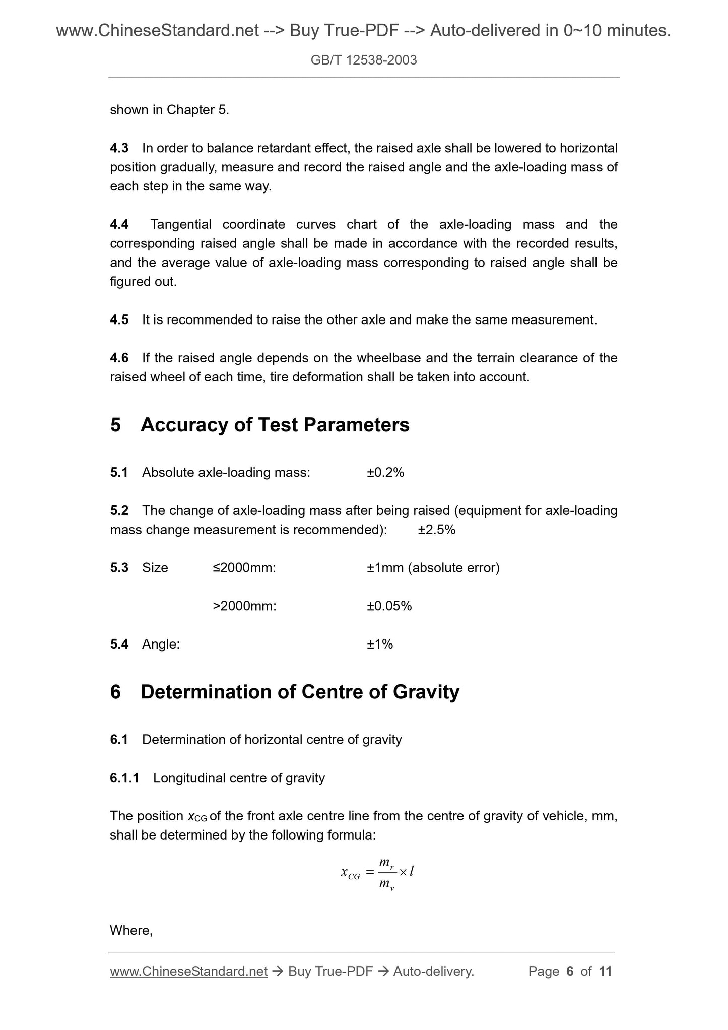
6.1 Determination of horizontal centre of gravity
6.1.1 Longitudinal centre of gravity
The position xCG of the front axle centre line from the centre of gravity of vehicle, mm,
shall be determined by the following formula:
mx
CG 
Where,
mr -- the rear axle-loading mass, mr=m3+m4, kg;
mv -- the total mass of vehicle, mv=m1+m2+m3+m4, kg;
l -- the wheelbase, l=0.5(lleft+lrigh), mm.
6.1.2 Horizontal centre of gravity
The horizontal centre of gravity shall be set at yCG, mm. The value is the horizontal
distance from the longitudinal symmetrical plane to the centre of gravity.
rf
CG m
mmbmmb
y 2
)()( 4321 
Symbol definition is detailed in 4.1.
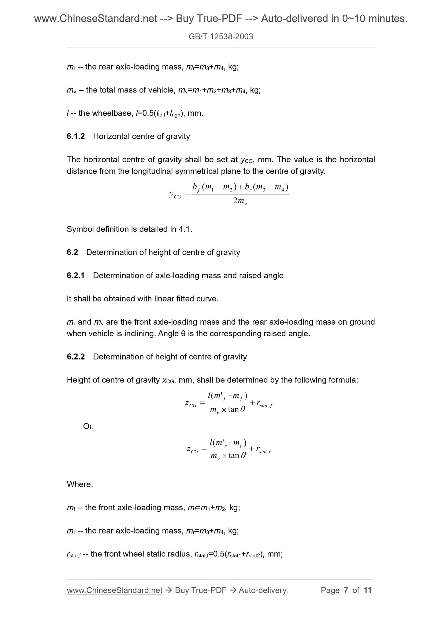
6.2 Determination of height of centre of gravity
6.2.1 Determination of axle-loading mass and raised angle
It shall be obtained with linear fitted curve.
mr and mv are the front axle-loading mass and the rear axle-loading mass on ground
when vehicle is inclining. Angle θ is the corresponding raised angle.
6.2.2 Determination of height of centre of gravity
Height of centre of gravity xCG, mm, shall be determined by the following formula:
fstat
ff
CG rm
mml
z ,tan
)'( 
 
Or,
rstat
rr
CG rm
mmlz ,tan
)'( 
 
Where,
mf -- the front axle-loading mass, mf=m1+m2, kg;
mr -- the rear axle-loading mass, mr=m3+m4, kg;
rstat,f -- the front wheel static radius, rstat,f=0.5(rstat1+rstat2), mm;

View full details