1
/
of
7
www.ChineseStandard.us -- Field Test Asia Pte. Ltd.
GB/T 12238-2008 English PDF (GB/T12238-2008)
Regular price
$105.00
Regular price
Sale price
$105.00
Unit price
/
per
Shipping calculated at checkout.
Couldn't load pickup availability
GB/T 12238-2008: Flanged and wafer resilient seal butterfly valves
Delivery: 9 seconds. Download (& Email) true-PDF + Invoice.
Get Quotation: Click GB/T 12238-2008 (Self-service in 1-minute)
Historical versions (Master-website): GB/T 12238-2008
Preview True-PDF (Reload/Scroll-down if blank)
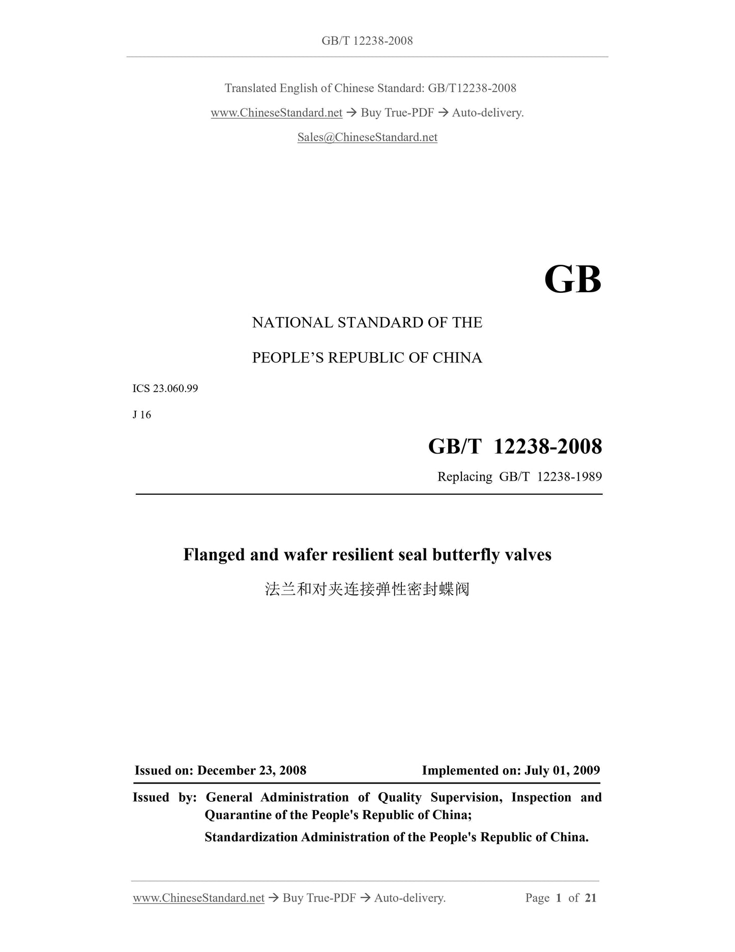
GB/T 12238-2008
GB
NATIONAL STANDARD OF THE
PEOPLE’S REPUBLIC OF CHINA
ICS 23.060.99
J 16
Replacing GB/T 12238-1989
Flanged and wafer resilient seal butterfly valves
ISSUED ON: DECEMBER 23, 2008
IMPLEMENTED ON: JULY 01, 2009
Issued by: General Administration of Quality Supervision, Inspection and
Quarantine of the People's Republic of China;
Standardization Administration of the People's Republic of China.
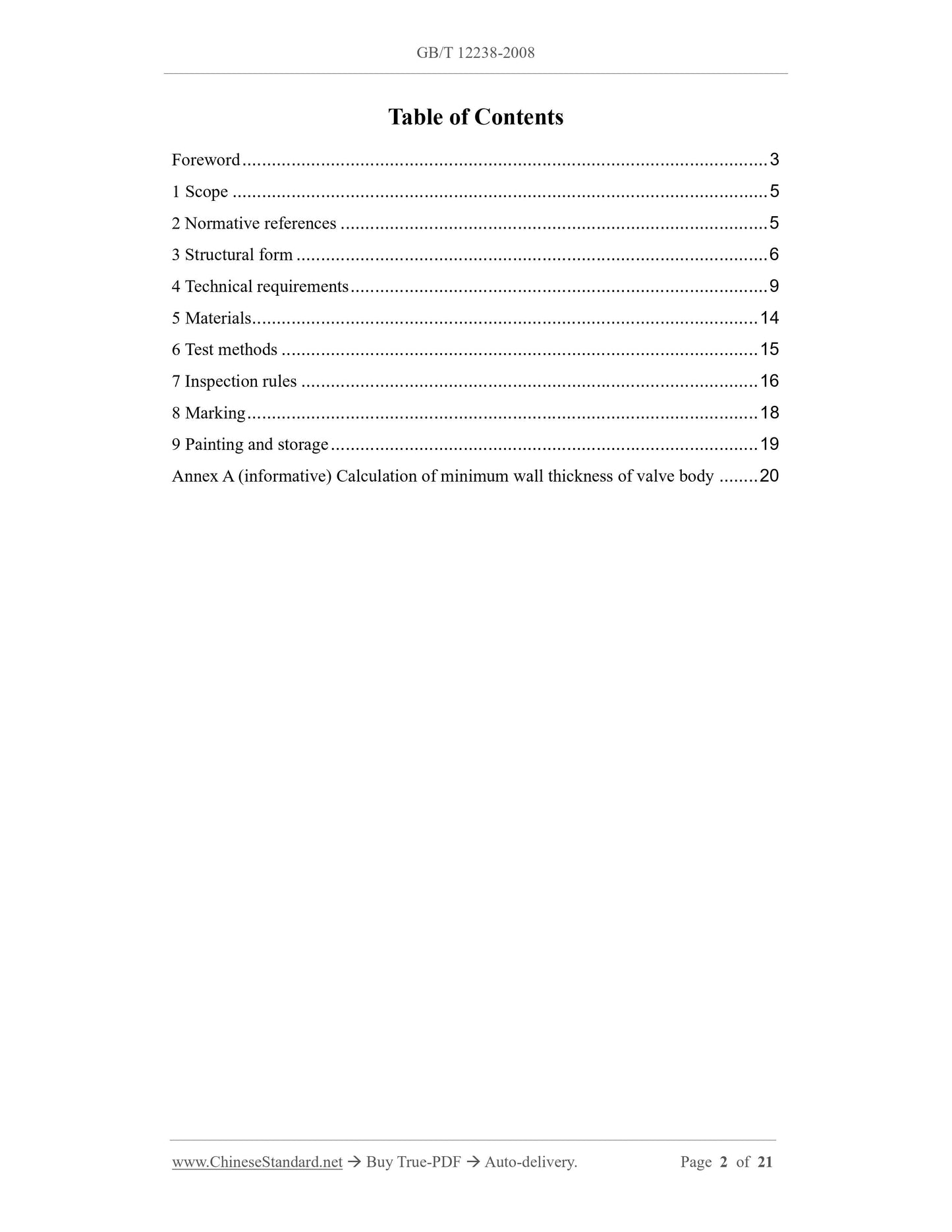
Table of Contents
Foreword ... 3
1 Scope ... 5
2 Normative references ... 5
3 Structural form ... 6
4 Technical requirements ... 9
5 Materials ... 14
6 Test methods ... 15
7 Inspection rules ... 16
8 Marking ... 18
9 Painting and storage ... 19
Annex A (informative) Calculation of minimum wall thickness of valve body ... 20
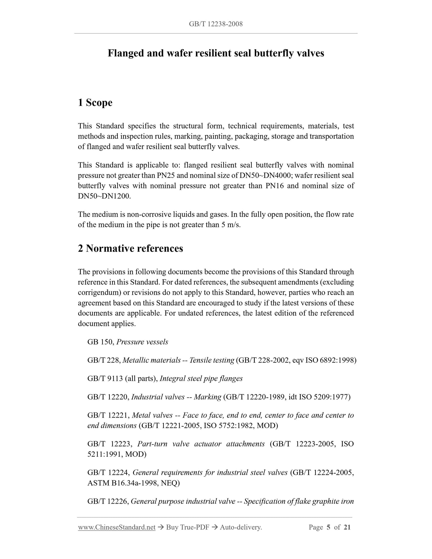
Flanged and wafer resilient seal butterfly valves
1 Scope
This Standard specifies the structural form, technical requirements, materials, test
methods and inspection rules, marking, painting, packaging, storage and transportation
of flanged and wafer resilient seal butterfly valves.
This Standard is applicable to: flanged resilient seal butterfly valves with nominal
pressure not greater than PN25 and nominal size of DN50~DN4000; wafer resilient seal
butterfly valves with nominal pressure not greater than PN16 and nominal size of
DN50~DN1200.
The medium is non-corrosive liquids and gases. In the fully open position, the flow rate
of the medium in the pipe is not greater than 5 m/s.
2 Normative references
The provisions in following documents become the provisions of this Standard through
reference in this Standard. For dated references, the subsequent amendments (excluding
corrigendum) or revisions do not apply to this Standard, however, parties who reach an
agreement based on this Standard are encouraged to study if the latest versions of these
documents are applicable. For undated references, the latest edition of the referenced
document applies.
GB 150, Pressure vessels
GB/T 228, Metallic materials -- Tensile testing (GB/T 228-2002, eqv ISO 6892:1998)
GB/T 9113 (all parts), Integral steel pipe flanges
GB/T 12220, Industrial valves -- Marking (GB/T 12220-1989, idt ISO 5209:1977)
GB/T 12221, Metal valves -- Face to face, end to end, center to face and center to
end dimensions (GB/T 12221-2005, ISO 5752:1982, MOD)
GB/T 12223, Part-turn valve actuator attachments (GB/T 12223-2005, ISO
5211:1991, MOD)
GB/T 12224, General requirements for industrial steel valves (GB/T 12224-2005,
ASTM B16.34a-1998, NEQ)
GB/T 12226, General purpose industrial valve -- Specification of flake graphite iron
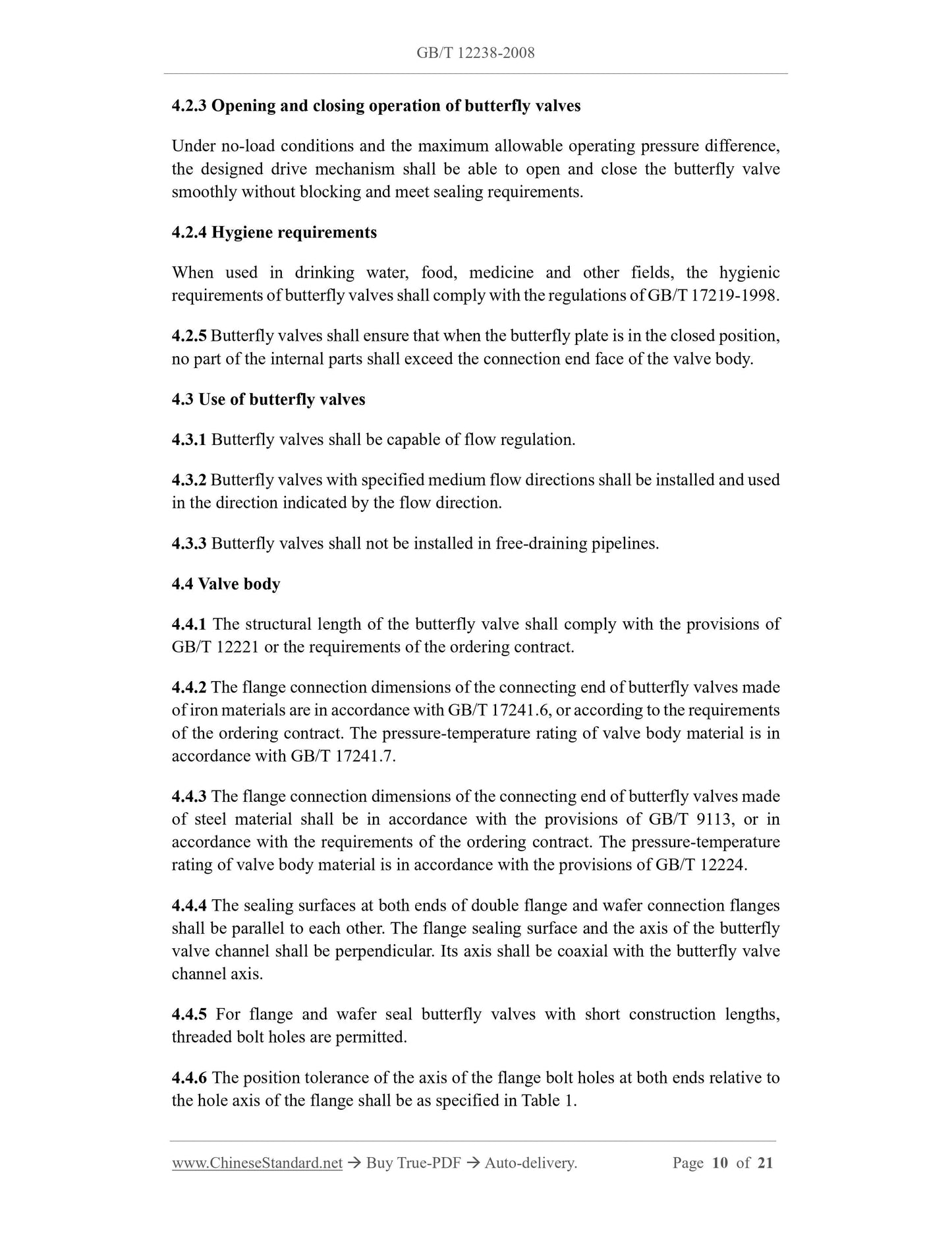
4.2.3 Opening and closing operation of butterfly valves
Under no-load conditions and the maximum allowable operating pressure difference,
the designed drive mechanism shall be able to open and close the butterfly valve
smoothly without blocking and meet sealing requirements.
4.2.4 Hygiene requirements
When used in drinking water, food, medicine and other fields, the hygienic
requirements of butterfly valves shall comply with the regulations of GB/T 17219-1998.
4.2.5 Butterfly valves shall ensure that when the butterfly plate is in the closed position,
no part of the internal parts shall exceed the connection end face of the valve body.
4.3 Use of butterfly valves
4.3.1 Butterfly valves shall be capable of flow regulation.
4.3.2 Butterfly valves with specified medium flow directions shall be installed and used
in the direction indicated by the flow direction.
4.3.3 Butterfly valves shall not be installed in free-draining pipelines.
4.4 Valve body
4.4.1 The structural length of the butterfly valve shall comply with the provisions of
GB/T 12221 or the requirements of the ordering contract.
4.4.2 The flange connection dimensions of the connecting end of butterfly valves made
of iron materials are in accordance with GB/T 17241.6, or according to the requirements
of the ordering contract. The pressure-temperature rating of valve body material is in
accordance with GB/T 17241.7.
4.4.3 The flange connection dimensions of the connecting end of butterfly valves made
of steel material shall be in accordance with the provisions of GB/T 9113, or in
accordance with the requirements of the ordering contract. The pressure-temperature
rating of valve body material is in accordance with the provisions of GB/T 12224.
4.4.4 The sealing surfaces at both ends of double flange and wafer connection flanges
shall be parallel to each other. The flange sealing surface and the axis of the butterfly
valve channel shall be perpendicular. Its axis shall be coaxial with the butterfly valve
channel axis.
4.4.5 For flange and wafer seal butterfly valves with short construction lengths,
threaded bolt holes are permitted.
4.4.6 The position tolerance of the axis of the flange bolt holes at both ends relative to
the hole axis of the flange shall be as specified in Table 1.
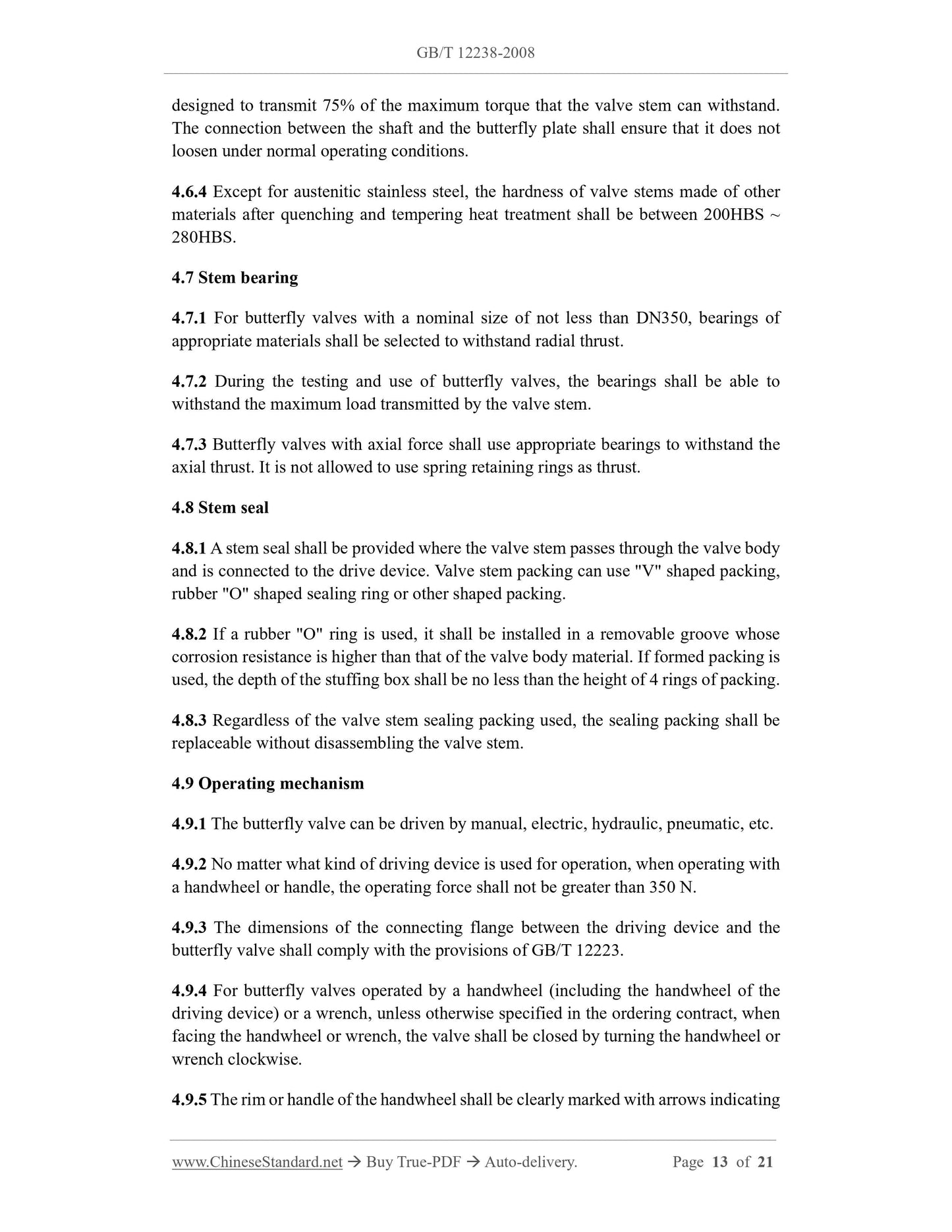
designed to transmit 75% of the maximum torque that the valve stem can withstand.
The connection between the shaft and the butterfly plate shall ensure that it does not
loosen under normal operating conditions.
4.6.4 Except for austenitic stainless steel, the hardness of valve stems made of other
materials after quenching and tempering heat treatment shall be between 200HBS ~
280HBS.
4.7 Stem bearing
4.7.1 For butterfly valves with a nominal size of not less than DN350, bearings of
appropriate materials shall be selected to withstand radial thrust.
4.7.2 During the testing and use of butterfly valves, the bearings shall be able to
withstand the maximum load transmitted by the valve stem.
4.7.3 Butterfly valves with axial force shall use appropriate bearings to withstand the
axial thrust. It is not allowed to use spring retaining rings as thrust.
4.8 Stem seal
4.8.1 A stem seal shall be provided where the valve stem passes through the valve body
and is connected to the drive device. Valve stem packing can use "V" shaped packing,
rubber "O" shaped sealing ring or other shaped packing.
4.8.2 If a rubber "O" ring is used, it shall be installed in a removable groove whose
corrosion resistance is higher than that of the valve body material. If formed packing is
used, the depth of the stuffing box shall be no less than the height of 4 rings of packing.
4.8.3 Regardless of the valve stem sealing packing used, the sealing packing shall be
replaceable without disassembling the valve stem.
4.9 Operating mechanism
4.9.1 The butterfly valve can be driven by manual, electric, hydraulic, pneumatic, etc.
4.9.2 No matter what kind of driving device is used for operation, when operating with
a handwheel or handle, the operating force shall not be greater than 350 N.
4.9.3 The dimensions of the connecting flange between the driving device and the
butterfly valve shall comply with the provisions of GB/T 12223.
4.9.4 For butterfly valves operated by a handwheel (including the handwheel of the
driving device) or a wrench, unless otherwise specified in the ordering contract, when
facing the handwheel or wrench, the valve shall be closed by turning the handwheel or
wrench clockwise.
4.9.5 The rim or handle of the handwheel shall be clearly marked with arrows indicating
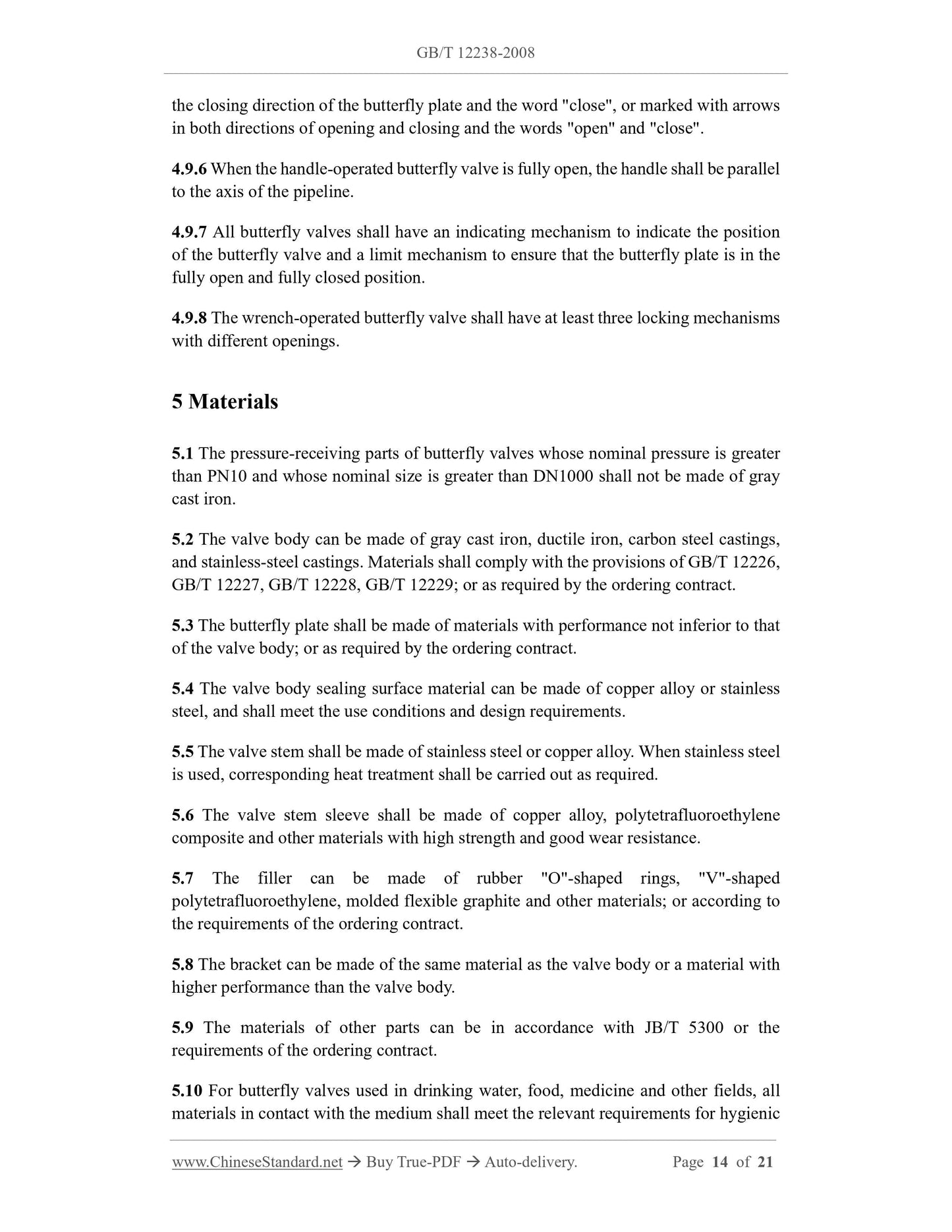
the closing direction of the butterfly plate and the word "close", or marked with arrows
in both directions of opening and closing and the words "open" and "close".
4.9.6 When the handle-operated butterfly valve is fully open, the handle shall be parallel
to the axis of the pipeline.
4.9.7 All butterfly valves shall have an indicating mechanism to indicate the position
of the butterfly valve and a limit mechanism to ensure that the butterfly plate is in the
fully open and fully closed position.
4.9.8 The wrench-operated butterfly valve shall have at least three locking mechanisms
with different openings.
5 Materials
5.1 The pressure-receiving parts of butterfly valves whose nominal pressure is greater
than PN10 and whose nominal size is greater than DN1000 shall not be made of gray
cast iron.
5.2 The valve body can be made of gray cast iron, ductile iron, carbon steel castings,
and stainless-steel castings. Materials shall comply with the provisions of GB/T 12226,
GB/T 12227, GB/T 12228, GB/T 12229; or as required by the ordering contract.
5.3 The butterfly plate shall be made of materials with performance not inferior to that
of the valve body; or as required by the ordering contract.
5.4 The valve body sealing surface material can be made of copper alloy or stainless
steel, and shall meet the use conditions and design requirements.
5.5 The valve stem shall be made of stainless steel or copper alloy. When stainless steel
is used, corresponding heat treatment shall be carried out as required.
5.6 The valve stem sleeve shall be made of copper alloy, polytetrafluoroethylene
composite and other materials with high strength and good wear resistance.
5.7 The filler can be made of rubber "O"-shaped rings, "V"-shaped
polytetrafluoroethylene, molded flexible graphite and other materials; or according to
the requirements of the ordering contract.
5.8 The bracket can be made of the same material as the valve body or a material with
higher performance than the valve body.
5.9 The materials of other parts can be in accordance with JB/T 5300 or the
requirements of the ordering contract.
5.10 For butterfly valves used in drinking water, food, medicine and other fields, all
materials in contact with the medium shall meet the relevant requirements for hygienic
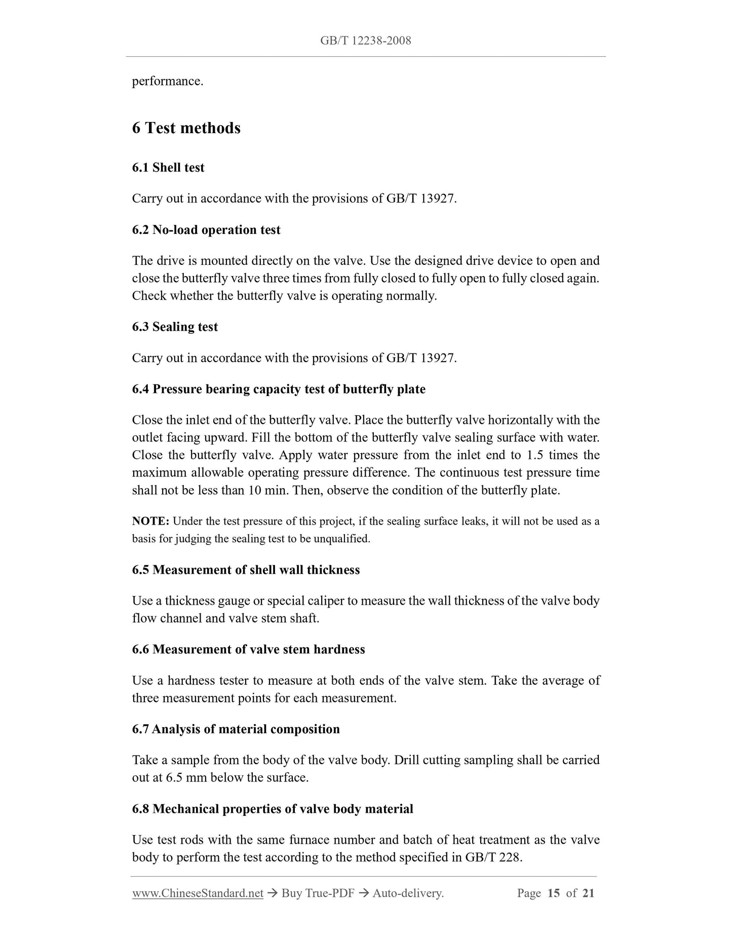
performance.
6 Test methods
6.1 Shell test
Carry out in accordance with the provisions of GB/T 13927.
6.2 No-load operation test
The drive is mounted directly on the valve. Use the designed drive device to open and
close the butterfly valve three times from fully closed to fully open to fully closed again.
Check whether the butterfly valve is operating normally.
6.3 Sealing test
Carry out in accordance with the provisions of GB/T 13927.
6.4 Pressure bearing capacity test of butterfly plate
Close the inlet end of the butterfly valve. Place the butterfly valve horizontally with the
outlet facing upward. Fill the bottom of the butterfly valve sealing surface with water.
Close the butterfly valve. Apply water pressure from the inlet end to 1.5 times the
maximum allowable operating pressure difference. The continuous test pressure time
shall not be less than 10 min. Then, observe the condition of the butterfly plate.
NOTE: Under the test pressure of this project, if the sealing surface leaks, it will not be used as a
basis for judging the sealing test to be unqualified.
6.5 Measurement of shell wall thickness
Use a thickness gauge or special caliper to measure the wall thickness of the valve body
flow channel and valve stem shaft.
6.6 Measurement of valve stem hardness
Use a hardness tester to measure at both ends of the valve stem. Take the average of
three measurement points for each measurement.
6.7 Analysis of material composition
Take a sample from the body of the valve body. Drill cutting sampling shall be carried
out at 6.5 mm below the surface.
6.8 Mechanical properties of valve body material
Use test rods with the same furnace number and batch of heat treatment as the valve
body to perform the test according to the method specified in GB/T 228.
GB/T 12238-2008
GB
NATIONAL STANDARD OF THE
PEOPLE’S REPUBLIC OF CHINA
ICS 23.060.99
J 16
Replacing GB/T 12238-1989
Flanged and wafer resilient seal butterfly valves
ISSUED ON: DECEMBER 23, 2008
IMPLEMENTED ON: JULY 01, 2009
Issued by: General Administration of Quality Supervision, Inspection and
Quarantine of the People's Republic of China;
Standardization Administration of the People's Republic of China.
Table of Contents
Foreword ... 3
1 Scope ... 5
2 Normative references ... 5
3 Structural form ... 6
4 Technical requirements ... 9
5 Materials ... 14
6 Test methods ... 15
7 Inspection rules ... 16
8 Marking ... 18
9 Painting and storage ... 19
Annex A (informative) Calculation of minimum wall thickness of valve body ... 20
Flanged and wafer resilient seal butterfly valves
1 Scope
This Standard specifies the structural form, technical requirements, materials, test
methods and inspection rules, marking, painting, packaging, storage and transportation
of flanged and wafer resilient seal butterfly valves.
This Standard is applicable to: flanged resilient seal butterfly valves with nominal
pressure not greater than PN25 and nominal size of DN50~DN4000; wafer resilient seal
butterfly valves with nominal pressure not greater than PN16 and nominal size of
DN50~DN1200.
The medium is non-corrosive liquids and gases. In the fully open position, the flow rate
of the medium in the pipe is not greater than 5 m/s.
2 Normative references
The provisions in following documents become the provisions of this Standard through
reference in this Standard. For dated references, the subsequent amendments (excluding
corrigendum) or revisions do not apply to this Standard, however, parties who reach an
agreement based on this Standard are encouraged to study if the latest versions of these
documents are applicable. For undated references, the latest edition of the referenced
document applies.
GB 150, Pressure vessels
GB/T 228, Metallic materials -- Tensile testing (GB/T 228-2002, eqv ISO 6892:1998)
GB/T 9113 (all parts), Integral steel pipe flanges
GB/T 12220, Industrial valves -- Marking (GB/T 12220-1989, idt ISO 5209:1977)
GB/T 12221, Metal valves -- Face to face, end to end, center to face and center to
end dimensions (GB/T 12221-2005, ISO 5752:1982, MOD)
GB/T 12223, Part-turn valve actuator attachments (GB/T 12223-2005, ISO
5211:1991, MOD)
GB/T 12224, General requirements for industrial steel valves (GB/T 12224-2005,
ASTM B16.34a-1998, NEQ)
GB/T 12226, General purpose industrial valve -- Specification of flake graphite iron
4.2.3 Opening and closing operation of butterfly valves
Under no-load conditions an...
Share